Table of Contents
Advertisement
Quick Links
Advertisement
Table of Contents

Related Manuals for Contec bx200 SERIES


Summary of Contents for Contec bx200 SERIES
- Page 1 IPC Series BOX-PC for BX200 Series User’s Manual CONTEC CO.,LTD.
-
Page 2: Check Your Package
*1 It is attached to the main body. *2 Please confirm latest information on the CONTEC homepage though the user's manual is stored in Recovery Media. The installation method is described in this document as well as the UsersManual. [File storing place: \Manual]... -
Page 3: Copyright
No part of this document may be copied or reproduced in any form by any means without prior written consent of CONTEC CO., LTD. CONTEC CO., LTD. makes no commitment to update or keep current the information contained in this document. -
Page 4: Table Of Contents
Table of Contents Check your package ..........................i Copyright..............................ii Trademarks ..............................ii Table of Contents ...........................iii INTRODUCTION About the Product ........................... 1 Features ............................1 Supported OS ........................... 2 Customer Support............................ 3 Web Site ............................3 Limited One-Year Warranty ........................3 How to Obtain Service.......................... - Page 5 Rear View ............................21 System Configuration..........................22 Component Function ..........................23 LED: POWER, ACCESS, STATUS .....................23 DC Power Input Connector: DC-IN ....................23 POWER SW ...........................23 Analog RGB Interface: A-RGB (BX-2x0 model).................24 DVI-D Interface: DVI-D (BX-2x0D model).................25 Giga bit-Ethernet: LAN A, B ......................26 Serial Port Interface: SERIAL A, B ....................27 USB Ports TYPE-A:USB TYPE-A ....................28 miniUSB Ports TYPE-AB:miniUSB TYPE-AB................28 CF Card Connector (Primary IDE Connection) : CF1 - 2 ............35...
- Page 6 Super IO Device ............................ 72 Power Management Setup ........................74 PnP/PCI Configuration Setup ....................... 76 PC Health Status ........................... 77 Frequency/Voltage Control........................78 Defaults Menu ............................79 Supervisor /User Password Setting ...................... 80 Exit Selecting ............................81 POST Messages............................. 81 POST Beep ............................
- Page 7 BX-2x0-DCxxxx, BX-2x0D-DCxxxx User’s manual...
-
Page 8: Introduction
Embedded-type CPU and chip set have been adopted. The use of readily available parts ensures the ease of the use of the product. In addition, the use of Contec-customized BIOS allows support to be provided at the BIOS level. -
Page 9: Supported Os
1. Introduction Can be installed in spaces only 50-mm thick with roughly the same area as a paperback book. It largely serves downsizing of your equipment, fits any area with the aestheticness kept. Slitless/fanless design that reduces maintenance work This product's spindleless design eliminates the heat dissipating slit and CPU fan and adopts CF card for the storage. -
Page 10: Customer Support
You can download updated driver software and differential files as well as sample programs available in several languages. Note! For product information Contact your retailer if you have any technical question about a CONTEC product or need its price, delivery time, or estimate information. Limited One-Year Warranty CONTEC products are warranted by CONTEC CO., LTD. -
Page 11: Safety Precautions
1. Introduction Safety Precautions Understand the following definitions and precautions to use the product safely. Safety Information This document provides safety information using the following symbols to prevent accidents resulting in injury or death and the destruction of equipment and resources. Understand the meanings of these labels to operate the equipment safely. - Page 12 To prevent corruption of files, always shutdown the OS before turning off this product. CONTEC reserves the right to refuse to service a product modified by the user. In the event of failure or abnormality (foul smells or excessive heat generation), unplug the power cord immediately and contact your retailer.
- Page 13 1. Introduction FCC PART 15 Class A Notice NOTE This equipment has been tested and found to comply with the limits for a Class A digital device, pursuant to part 15 of the FCC Rules. These limits are designed to provide reasonable protection against harmful interference when the equipment is operated in commercial environment.
-
Page 14: System Reference
2. System Reference System Reference Specification Table 2.1. Functional Specification < 1 / 2 > Model BX-200-DCxxxx BX-200D-DCxxxx BX-210-DCxxxx BX-210D-DCxxxx Intel® Atom (TM) Processor Z510P Intel® Atom (TM) Processor Z530P 1.10GHz (FSB400MHz) 1.60GHz (FSB533MHz) Chip set Intel® US15WP BIOS BIOS (mfd. by Award) Memory 200pin SO-DIMM socket x 1, PC2-4300 (DDR2 533) DDR2 SDRAM support BX-2x0-DC5xxx, BX-2x0D-DC5xxx: 1GB, BX-2x0-DC6xxx, BX-2x0D-DC6xxx: 2GB... - Page 15 2. System Reference Table 2.1. Functional Specification < 2 / 2 > Model BX-200-DCxxxx BX-200D-DCxxxx BX-210-DCxxxx BX-210D-DCxxxx Interface Display 1 port 1 port 1 port 1 port (15 pin HD-SUB (24 pin connector (15 pin HD-SUB (24 pin connector connector [Analog [DVI-D] x 1) connector [Analog [DVI-D] x 1)
-
Page 16: Power Management Features
2. System Reference Table 2.2. Installation Environment Requirements BX-2x0-DCxxxx, BX-2x0D-DCxxxx Model Operating temperature 0 - 50°C (When using 1000BASE-T : 0 - 45°C) *4 Storage temperature -10 - 60°C Humidity 10 - 90%RH (No condensation) Floating dust particles Not to be excessive Corrosive gases None AC line / ±2kV *5,... -
Page 17: Power Requirements
2. System Reference Power Requirements Your system requires a clean, steady power source for reliable performance of the high frequency CPU on the product, the quality of the power supply is even more important. For the best performance makes sure your power supply provides a range of 10.8 V minimum to 31.2 V maximum DC power source. -
Page 18: Physical Dimensions
2. System Reference Physical Dimensions BX-2x0-DCxxxx *1 : The length (L) from the surface of the cabinet to the screw tip should be 8mm or less. *2 : When you fasten the bundled attachment fittings to be fixed to the body, you should use the attached screws (M3 x 6). Otherwise, the length (L) from the surface of the cabinet to the screw tip should be 4mm or less. - Page 19 2. System Reference BX-2x0-DCxxxx, BX-2x0D-DCxxxx User’s manual...
-
Page 20: Hardware Setup
3. Hardware Setup 3. Hardware Setup Before Using the Product for the First Time Follow the next steps to set up this product : STEP1 By referring to the information in this chapter, install, connect and set this product. STEP2 Connect cables. -
Page 21: Hardware Setup
3. Hardware Setup Hardware Setup Before you start, be sure that the power is turned off. Remove only those screws that are explained. Do not move any other screw. Inserting an Embedded CF Card One CF card (Type I) can be embedded. BX-2x0-DCx311 and BX-2x0D-DCx311 come with CF cards with the OS already installed. -
Page 22: Attaching The Attachment Fittings
3. Hardware Setup Attaching the Attachment Fittings (1) Use screws to attach the bundled attachment fittings with a screw. Do not tighten screws with excess force. *1 Attached screw (M3 x 6) Figure 3.3. Attaching the Attachment Fittings CAUTION Screw holes may be damaged if screws are tightened with a torque greater than the specified torque. The specified tightening torque is 5 - 6kgf⋅cm. -
Page 23: Fastening The Cable
3. Hardware Setup Fastening the Cable This product comes with clamps for fixing cables. Fastening the LINEOUT, USB Cable (1) The system unit has a hole for attaching cable clamp to USB removal prevention fitting. Using a cable clamp for a cable with lock-less connector, such as the LINEOUT and USB Cable, prevents the connector from being unplugged. -
Page 24: Installation Requirements
3. Hardware Setup Installation Requirements There are limits to the ambient temperature range depending on the installation orientation. Be sure that the operating temperature is within the range specified in the installation environment requirement by making space between the product and device that generates heat or exhaust air. Installable directions at operating temperature 0 - +50°C: (1), (2), (3), (4), (5) (When using 1000BASE-T: 0 - +45°C) Installable directions at operating temperature 0 - +45°C (6), (7), (8) - Page 25 3. Hardware Setup Distances between this product and its vicinity Figure 3.8. Distances between this product and its vicinity CAUTION Do not install this product in completely sealed spaces, except when it is possible to adjust the internal temperature using an air conditioner or similar equipment. Temperature increase caused by long-term usage may result in operational malfunction or other problems.
- Page 26 3. Hardware Setup Operating temperature In this product, the operating temperature is decided from the multiple measurement points as shown below. When making use of the product, the air current should be adjusted to prevent that all the temperatures measured at the measurement points exceed the specified temperature. Figure 3.9.
- Page 27 3. Hardware Setup BX-2x0-DCxxxx, BX-2x0D-DCxxxx User’s manual...
-
Page 28: Each Component Function
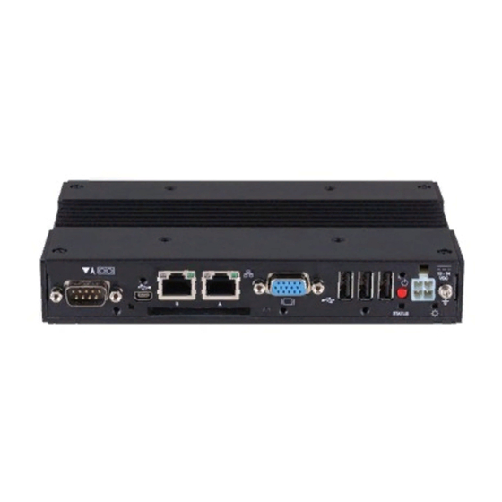
4. Each Component Function 4. Each Component Function Component Name Front View BX-2x0-DCxxxx BX-2x0D-DCxxxx Figure 4.1. Component Name < 1 / 2 > Rear View BX-2x0-DCxxxx, BX-2x0D-DCxxxx Figure 4.1. Component Name < 2 / 2 > BX-2x0-DCxxxx, BX-2x0D-DCxxxx User’s manual... -
Page 29: System Configuration
4. Each Component Function Table 4.1. Component Function Name Function POWER LED Power ON display LED STATUS LED Status LED ACCESS LED CF disk access display LED DC-IN DC power input connector POWER-SW Power switch USB TYPE-A USB port TYPE-A connector x 5 miniUSB TYPE-AB miniUSB port TYPE-AB connector x 1 A-RGB(BX-2x0 model) -
Page 30: Component Function
You can control the behavior of LED from the user application. *1 API that controls STATUS LED is available. See the API description file "mtdll_e.chm" included in /RasUtility/Samples in the CONTEC’s Web site [IPC-SLIB-01] for details. DC Power Input Connector: DC-IN To supply the power, always use the power supply listed below. -
Page 31: Analog Rgb Interface: A-Rgb (Bx-2X0 Model)
Display driver Install the appropriate audio driver for your OS from the bundled CD-ROM [IPC-SLIB-01]. (For information on the latest version of IPC-SLIB-01, check the CONTEC's web site.) CAUTION When the analog display is used, Windows MS-DOS may not be properly displayed in full-screen mode. -
Page 32: Dvi-D Interface: Dvi-D (Bx-2X0D Model)
4. Each Component Function DVI-D Interface: DVI-D (BX-2x0D model) A DVI-D interface is provided. A CONTEC flat panel display can be connected. The connector is named DVI-D (DVI-D 24-pin). Table 4.5. DVI-D Connector Connector type DVI-D 24 pin Pin No. -
Page 33: Giga Bit-Ethernet: Lan A, B
: Operation LED 10M: Off, 100M: Green, 1000M: Orange LAN drivers Install the appropriate audio driver for your OS from the CONTEC’s Web site [IPC-SLIB-01]. (For information on the latest version of IPC-SLIB-01, check the CONTEC's web site.) CAUTION Attention should to be paid to the guaranteed operating range of temperature in using 1000BASE-T. -
Page 34: Serial Port Interface: Serial A, B
4. Each Component Function Serial Port Interface: SERIAL A, B SERIAL A, B (RS-232C Ports) The product has 2 channels of RS-232C compliant serial ports supporting up to a baud rate of 115,200bps with a 16-byte transmission-dedicated data buffer and a 16-byte reception-dedicated data buffer. You can use “Chapter 5 BIOS Setup”... -
Page 35: Usb Ports Type-A:usb Type-A
4. Each Component Function USB Ports TYPE-A:USB TYPE-A This product is equipped with 5 channels for USB 2.0 interface. Table 4.9. USB Connector TYPE-A Pin No. Function USB_VCC USB- USB+ USB_GND miniUSB Ports TYPE-AB:miniUSB TYPE-AB This product is equipped with 1 channel for USB 2.0 TYPE-AB interface. Table 4.10. - Page 36 4. Each Component Function (3) When the window below is displayed, under "File sharing" select the "On" option. (4) When the window below is displayed, select the shared folder you want to use and configure it. Complete the "Share path" and "Share name" fields, and click [Add] to add the folder to the list of current shares on your system.
- Page 37 (8) Next, install the Intel® USB Client Host Utility on the PC that you want to connect to. The setup files for the utility are included in IPC-SLIB-01. (For the latest version of IPC-SLIB-01, visit the CONTEC website.) Note: Do not connect the USB cable to this product at this stage.
- Page 38 4. Each Component Function (9) When the window below is displayed, click [Next] to proceed. (10) When the window below is displayed, read the license agreement and click [Yes] to accept the terms. (11) Read the installation information and confirm that your PC meets the system requirements. BX-2x0-DCxxxx, BX-2x0D-DCxxxx User’s manual...
- Page 39 4. Each Component Function (12) When the window below is displayed, select "Install the utility", confirm the installation directory, and then select [Next]. (13) If the window below is displayed during the installation, select [Continue Anyway]. (14) When the installation finishes, the windows below are displayed. Select [Next] and then [Finish] to complete the installation.
- Page 40 4. Each Component Function (15) Next, launch the utility to configure it. When the window below is displayed, prepare to connect this product to the PC using the USB cable, and click [Next]. (16) The window below is displayed. Connect this product to the PC using the USB cable. (17) If the window below is displayed, click [Next].
- Page 41 4. Each Component Function (18) Once the installation is finished, from Network Connections, select the newly added local area connection, and display the "Internet Protocol (TCP/IP) Properties". Check that the PC is on the same subnet as this product. Change the values if they are different. (19) It is now possible to use shares on this product as network drives.
-
Page 42: Cf Card Connector (Primary Ide Connection) : Cf1 - 2
4. Each Component Function CF Card Connector (Primary IDE Connection) : CF1 - 2 The CF Card (Type I : dedicated to the memory card) can be connected. The CF card connector doesn't support hot plug. The pulling out opening of the CF card cannot be done in the state of power supply ON. -
Page 43: Line Out Interface: Line Out
The audio driver is required to use the microphone input and line output interfaces. Install the appropriate audio driver for your OS from the CONTEC’s Web site CD-ROM [IPC-SLIB-01]. (For information on the latest version of IPC-SLIB-01, check the CONTEC's Web site.) RAS Functions A RAS port is provided for this product. - Page 44 Close (2) Example programming The following example is written in Intel 8086 assembly language. The utility in IPC-SLIB-01 allows you to use this language in Windows. (For the latest version of IPC-SLIB-01, visit the CONTEC website.) ;------------------------------------------- ;Open ;------------------------------------------- CHK_OPEN1:...
- Page 45 4. Each Component Function ;------------------------------------------- CHK_CMD: DX,2A4H AL,DX TEST AL,2 ;Check status of output CHK_CMD DX,2A0H AL,93H ;Set 485 Command DX,AL CHK_DATA: DX,2A4H AL,DX TEST AL, 2 ;Check status of output CHK_DATA DX,2A0H AL, 0 ;Bit0: 0 Receiver Disable, 1 Receiver Enable ;Bit1: 0 Transmitter Disable, 1 Transmitter Enable CHK_STA: DX,2A4H...
- Page 46 4. Each Component Function Connection methods Figure 4.4. Half-Duplex Connection Method Figure 4.5. Full-Duplex Connection Method * RE and TE respectively indicate Bit0 and Bit1 settings data in the sample program. BX-2x0-DCxxxx, BX-2x0D-DCxxxx User’s manual...
-
Page 47: General Purpose Input/Output And Remote Power On/Reset
4. Each Component Function General Purpose Input/Output and Remote Power On/Reset This product is equipped with three general purpose insulation-type inputs and outputs. Inputs can be used as remote power on and remote reset inputs. It is necessary to configure BIOS settings to use an input signal as a remote power on or remote reset signal. - Page 48 4. Each Component Function (2) Example programming The following example is written in Intel 8086 assembly language. The utility in IPC-SLIB-01 allows you to use this language in Windows. (For the latest version of IPC-SLIB-01, visit the CONTEC website.) ;------------------------------------------- ;Open ;-------------------------------------------...
- Page 49 4. Each Component Function DX,2A0H AL,DX ;Command success if AL = 90H CHK_DI3: DX,2A4H AL,DX TEST AL,1 ;Check status of input CHK_DI3 DX,2A0H AL,DX ;AL is DI data(3bit LSB) ;------------------------------------------- ;Digital Output ;------------------------------------------- CHK_DO1: DX,2A4H AL,DX TEST AL,2 ;Check status of output CHK_DO1 DX,2A0H AL,91H...
- Page 50 4. Each Component Function CHK_CLOSE2: DX,2A4H AL,DX TEST AL,1 ;Check status of input CHK_CLOSE2 DX,02A0H AL,DX ;Close success if AL = 55H External I/O Circuit Figure 4.6. Input Circuit Figure 4.7. Output Circuit BX-2x0-DCxxxx, BX-2x0D-DCxxxx User’s manual...
- Page 51 4. Each Component Function BX-2x0-DCxxxx, BX-2x0D-DCxxxx User’s manual...
-
Page 52: Bios Setup
5. BIOS Setup 5. BIOS Setup Introduction This chapter discusses Award’s Setup program built into the FLASH ROM BIOS. The Setup program allows users to modify the basic system configuration. This special information is then stored in battery-backed RAM so that it retains the Setup information when the power is turned off. The rest of this chapter is intended to guide you through the process of configuring your system using Setup. -
Page 53: Using Setup
5. BIOS Setup Using Setup In general, you use the arrow keys to highlight items, press <Enter> to select, use the PageUp and PageDown keys to change entries, press <F1> for help and press <Esc> to quit. The following table provides more detail about how to navigate in the Setup program using the keyboard. -
Page 54: Main Menu
5. BIOS Setup Main Menu Once you enter the Award BIOS CMOS Setup Utility, the Main Menu will appear on the screen. The Main Menu allows you to select from several setup functions and two exit choices. Use the arrow keys to select among the items and press <Enter>... - Page 55 5. BIOS Setup PnP / PCI Configuration This entry appears if your system supports PnP / PCI. Load Fail-Safe Defaults Use this menu to load the BIOS default values for the minimal/stable performance for your system to operate. Load Optimized Defaults Use this menu to load the BIOS default values that are factory settings for optimal performance system operations.
-
Page 56: Standard Cmos Setup
5. BIOS Setup Standard CMOS Setup Figure 5.2. Standard CMOS Setup The items in Standard CMOS Setup Menu are divided into 10 categories. Each category includes no, one or more than one setup items. Use the arrow keys to highlight the item and then use the <PgUp> or <PgDn>... -
Page 57: Main Menu Selections
5. BIOS Setup Main Menu Selections This table shows the selections that you can make on the Main Menu. Table 5.2. Main Menu Selections Item Options Description Set the system date. Note that the Date Month DD YYYY ‘Day’ automatically changes when you set the date Time HH : MM : SS... -
Page 58: Ide Adapters
5. BIOS Setup IDE Adapters Table 5.3. IDE Adapters configurations Item Options Description Press Enter to auto-detect the CF card on this channel. If IDE HDD Auto-detection Press Enter detection is successful, it fills the remaining fields on this menu. Selecting ‘manual’... -
Page 59: Advanced Bios Features Setup
5. BIOS Setup Advanced BIOS Features Setup This section allows you to configure your system for basic operation. You have the opportunity to select the system’s default speed, boot-up sequence, keyboard operation, shadowing and security. CPU Feature [Press Enter] Item Help Hard Disk Boot Priority [Press Enter] Virus Warning... -
Page 60: Cpu Feature
5. BIOS Setup CPU Feature Figure 5.4. CPU Feature CPU Feature lets you configure original CPU settings. As supported functions differ depending on the type of CPU, some items may not be displayed for some CPUs. Table 5.4. CPU Features Selections Description Choice Delay Prior to Thermal... - Page 61 5. BIOS Setup Description Choice C1E Function Configures the CPU C1E (power saving when CPU load is low) function. Execute Disable Bit When disabled, forces the XD (data execution prevention) feature flag to always return 0. Virtualization technology Enables/disables the virtualization support function. BX-2x0-DCxxxx, BX-2x0D-DCxxxx User’s manual...
-
Page 62: Hard Disk Boot Priority
5. BIOS Setup Hard Disk Boot Priority Figure 5.5. Hard Disk Boot Priority CF cards, USB drives, and other connected hard disks are displayed, and an order of boot priority can be set. With the field, there is the option to choose, aside from the hard disks connected, “Bootable add-in Cards”... -
Page 63: Virus Warning
5. BIOS Setup Virus Warning When enabled, you receive a warning message if a program (specifically, a virus) attempts to write to the boot sector or the partition table of the hard disk drive. You should then run an anti-virus program. Keep in mind that this feature protects only the boot sector, not the entire hard drive. - Page 64 5. BIOS Setup Description Choice Quiet Post Skip certain self-diagnosis processes such as checking memory or other several devices for shorter bootup time. Default setting (Disabled) does not simplify the self-diagnosis process. Quick Power On Self Test Select Enabled to reduce the amount of time required to run the power-on self-test (POST).
- Page 65 5. BIOS Setup Description Choice Second Boot Device The BIOS attempts to load the operating system from the devices in the sequence selected in these items. Third Boot Device The BIOS attempts to load the operating system from the devices in the sequence selected in these items. Boot Other Device Sets whether or not to try booting from another device.
- Page 66 5. BIOS Setup Description Choice Gate A20 option Gate A20 refers to the way the system addresses memory above 1 MB (extended memory). When set to Fast, the system chipset controls Gate A20. When set to Normal, a pin in the keyboard controller controls Gate A20.
- Page 67 5. BIOS Setup Description Choice Security Option Select whether the password is required every time the system boots or only when you enter setup. If you have set a password, select whether the password is required every time the System boots, or only when you enter Setup. System: The system will not boot and access to Setup will be denied if the correct password is not entered at the prompt.
- Page 68 5. BIOS Setup Description Choice WDT Protect Time There is normally no need to change these settings. Use "Disabled". Post Code Show During BIOS startup, the Post Code is displayed at the right upper corner of the screen. The Post Code is shown, however, after the initialization of graphic device is finished and the system is ready for screen display.
-
Page 69: Advanced Chipset Features Setup
5. BIOS Setup Advanced Chipset Features Setup Figure 5.6. Advanced Chipset Features Setup Table 5.6. Advance Chipset Feature Selections Description Choice System BIOS Cacheable Selecting Enabled allows caching of the system BIOS ROM at F0000h-FFFFFh, resulting in better system performance. However, if any program writes to this memory area, a system error may result. -
Page 70: Vga Setting
5. BIOS Setup VGA setting The field under the On-Chip VGA Setting and their defaults settings are: Table 5.7. VGA Setting Selections Description Choice On-Chip Frame Buffer Size Lets you set the size of the VGA frame buffer. BX-2x0-DCxxxx, BX-2x0D-DCxxxx User’s manual... -
Page 71: Watch Dog Timer Setting
5. BIOS Setup Watch Dog Timer Setting These are settings of the output to the PO2 from watch dog timer for the RAS port. For the models without the RAS port(s), this setting item is not displayed. Table 5.8. Watch Dog Timer Setting Description Choice WDT Output to PO2... -
Page 72: Integrated Peripherals
5. BIOS Setup Integrated Peripherals This section sets configurations for your hard disk and other integrated peripherals. The first screen shows three main items for user to select. Once an item selected, a submenu appears. Details follow. Figure 5.7. Integrated Peripherals Table 5.9. -
Page 73: Onchip Ide Device
5. BIOS Setup OnChip IDE Device Figure 5.8. OnChip IDE Device Table 5.10. On Chip IDE Device Selections Description Choice IDE HDD Block mode Block mode is also called block transfer, multiple commands, or multiple sectors read/write. If the CF card supports block mode, when "Enabled"... - Page 74 5. BIOS Setup Description Choice IDE Primary Master / Slave PIO Sets the PIO mode (0-4) of the onboard IDE interface. If "Auto" is selected, the system automatically determines the optimal mode. IDE Primary Master/Slave UDMA Enables/disables IDE UDMA (Ultra DMA) transfer. If "Auto"...
-
Page 75: Onboard Device
5. BIOS Setup Onboard Device Figure 5.9. Onboard Device Table 5.11. Onboard Device Selections Description Choice Azalia/AC97 Audio Select Selects audio functions and enables/disables devices. There is normally no need to change these settings. Use "Auto". USB Client Controller To use this function, you must install a dedicated driver and configure settings. - Page 76 5. BIOS Setup Description Choice Onboard LAN A Select "Enabled" to use the onboard LAN A controller. Onboard LAN B Select "Enabled" to use the onboard LAN B controller. Onboard LAN Boot ROM Select "Enabled" to boot via PXE (network boot). This setting is used for both Onboard LAN A and B.
-
Page 77: Usb Device Setting
5. BIOS Setup USB Device Setting Figure 5.10. USB Device Setting Table 5.12. USB Device Setting Selections Description Choice USB 1.0 Controller Enables/disables the onboard USB 1.0 function. In normal cases, select "Enabled". BX-2x0-DCxxxx, BX-2x0D-DCxxxx User’s manual... -
Page 78: Bx-2X0-Dcxxxx, Bx-2X0D-Dcxxxx User's Manual
5. BIOS Setup Description Choice USB 2.0 Controller Enable or disable the Onboard USB 2.0 function. In normal cases, use it while “Enable”. USB Operation Mode Select one of USB operation mode. In normal cases, use it while “High Speed”. USB Keyboard Support Select “Enabled”... -
Page 79: Super Io Device
5. BIOS Setup Super IO Device Figure 5.11. Super IO Device Table 5.13. Super I/O device Selections Description Choice Onboard Serial Port A Select an address and corresponding interrupt for the serial port A. Onboard Serial Port B Select an address and corresponding interrupt for the serial port B. - Page 80 5. BIOS Setup Description Choice T.P. Serial Port Configures settings for the touch panel serial port. In normal cases, set it as “Disable”. RS485 Terminator Control Configures terminator settings for RAS connector and RS485 port. BX-2x0-DCxxxx, BX-2x0D-DCxxxx User’s manual...
-
Page 81: Power Management Setup
5. BIOS Setup Power Management Setup The Power Management Setup allows you to configure you system to most effectively save energy while operating in a manner consistent with your own style of computer use. Figure 5.12. Power Management Setup BX-2x0-DCxxxx, BX-2x0D-DCxxxx User’s manual... - Page 82 5. BIOS Setup Table 5.14. Power Management setup Selections Description Choice ACPI Function When set to ‘Enabled’, turns on the ACPI Function. By default, this field is “Enabled”. Note: ACPI (Advanced Configuration and Power Interface) is a power management specification that makes hardware status information available to the operating system ACPI enables a computer to turn its peripherals on and off for improved power management.
-
Page 83: Pnp/Pci Configuration Setup
5. BIOS Setup PnP/PCI Configuration Setup This section describes configuring the PCI bus system. PCI, or Personal Computer Interconnect, is a system which allows I/O devices to operate at speeds nearing the speed the CPU itself uses when communicating with its own special components. This section covers some very technical items and it is strongly recommended that only experienced users should make any changes to the default settings. -
Page 84: Pc Health Status
5. BIOS Setup PC Health Status Figure 5.14. PC Health Status The BIOS shows the PC health status in this window. Table 5.15. PC Health Status Selections Description Choices Current CPU Temp. This field displays the current CPU temperature. Vcore / 1.5V /5V / 12V This field displays the current voltage. -
Page 85: Frequency/Voltage Control
5. BIOS Setup Frequency/Voltage Control Figure 5.15. Frequency/Voltage Control Table 5.16. Frequency/Voltage Control Selections Description Choices Spread Spectrum When "Enabled" is selected, the waveform near the peak of the pulse created by the system clock generator is smoothed out to help reduce EMI. BX-2x0-DCxxxx, BX-2x0D-DCxxxx User’s manual... -
Page 86: Defaults Menu
5. BIOS Setup Defaults Menu Selecting “Defaults” from the main menu shows you two options which are described below Load Fail-Safe Defaults When you press <Enter> on this item you get a confirmation dialog box with a message similar to: Load Fail-Safe Defaults (Y/N) ? N Pressing ‘Y’... -
Page 87: Supervisor /User Password Setting
5. BIOS Setup Supervisor /User Password Setting You can set either supervisor or user password, or both of then. The differences between are: SUPERVISOR PASSWORD: can enter and change the options of the setup menus. USER PASSWORD: just can only enter but do not have the right to change the options of the setup menus. -
Page 88: Exit Selecting
5. BIOS Setup Exit Selecting Save & Exit Setup Pressing <Enter> on this item asks for confirmation : Save to CMOS and EXIT (Y/N)? Y Pressing “Y” stores the selections made in the menus in CMOS – a special section of memory that stays on after you turn your system off. -
Page 89: Error Messages
5. BIOS Setup Error Messages One or more of the following messages may be displayed if the BIOS detects an error during the POST. This list includes messages for both the ISA and the EISA BIOS. CMOS battery has failed CMOS battery is no longer functional. - Page 90 5. BIOS Setup System halted, (CTRL-ALT-DEL) to REBOOT… Indicates the present boot attempt has been aborted and the system must be rebooted. Press and hold down the CTRL and ALT keys and press DEL. Hard disk(s) fail (80) HDD reset failed. Hard disk(s) fail (40) HDD controller diagnostics failed.
- Page 91 5. BIOS Setup BX-2x0-DCxxxx, BX-2x0D-DCxxxx User’s manual...
-
Page 92: Appendix
6. Appendix 6. Appendix Memory Map Table 6.1. Memory Map Memory Segments Comments 00000h - 9FFFh 0 - 640K DOS Region A0000h - BFFFFh Video Buffer B0000h - B7FFFh Monochrome Adapter range C0000h - CFFFFh Video BIOS D0000h - DFFFFh Expansion Area E0000h - EFFFFh Extended System BIOS Area... -
Page 93: I/O Port Addresses
6. Appendix I/O Port Addresses Table 6.2. I/O Port Addresses Address Size Description 0000 - 000F 16 bytes DMA controller 0010 - 001F 16 bytes Reserved 0020 - 0021 2 bytes PIC interrupt controller 0022 - 003F 30 bytes Reserved 0040 - 0043 4 bytes System timer 1... -
Page 94: Interrupt Level List
6. Appendix Interrupt Level List Table 6.3. Hardware Interrupt Levels (Factory Settings) Type 8259 Priority Description Vector High -I/O CHK IRQ0 MASTER ↑ Timer 0 IRQ1 ” ⏐ System reserved IRQ2 ” ⏐ Interrupt controller 2 (slave) IRQ8 SLAVE ⏐ Real-time clock IRQ9 ”... -
Page 95: Post Codes
6. Appendix POST Codes Table 6.4. POST Codes < 1 / 5 > POST Description (hex) Test CMOS R/W functionality. Early chipset initialization: -Disable shadow RAM -Disable L2 cache (socket 7 or below) -Program basic chipset registers Detect memory -Auto-detection of DRAM size, type and ECC. -Auto-detection of L2 cache (socket 7 or below) Expand compressed BIOS code to DRAM Call chipset hook to copy BIOS back to E000 &... - Page 96 6. Appendix Table 6.4. POST Codes < 2 / 5 > POST Description (hex) Initial EARLY_PM_INIT switch. Reserved Load keyboard matrix (notebook platform) Reserved HPM initialization (notebook platform) Reserved Check validity of RTC value: e.g. a value of 5Ah is an invalid value for RTC minute. Load CMOS settings into BIOS stack.
- Page 97 6. Appendix Table 6.4. POST Codes < 3 / 5 > POST Description (hex) Reserved Test 8259 interrupt mask bits for channel 2. Reserved Reserved Test 8259 functionality. Reserved Reserved Reserved Initialize EISA slot Reserved Calculate total memory by testing the last double word of each 64K page. Program writes allocation for AMD K5 CPU.
- Page 98 6. Appendix Table 6.4. POST Codes < 4 / 5 > POST Description (hex) Reserved Prepare memory size information for function call: INT 15h ax=E820h Reserved Turn on L2 cache Reserved Program chipset registers according to items described in Setup & Auto-configuration table. Reserved 1.
- Page 99 6. Appendix Table 6.4. POST Codes < 5 / 5 > POST Description (hex) Reserved Reserved Reserved Reserved Reserved Reserved Reserved Read HDD boot sector information for Trend Anti-Virus code Enable L2 cache Program boot up speed Chipset final initialization. Power management final initialization Clear screen &...
-
Page 100: Com I/O Address And Register Function
6. Appendix COM I/O Address and Register Function The following table lists the I/O addresses in case of COM 1. Table 6.5. I/O Address I/O address DLAB Read/Write Register 03F8H Transmitter holding register Receive buffer register Divisor latch register (LSB) 03F9H Divisor latch register (MSB) Interrupt enable register... - Page 101 6. Appendix Table 6.5. Function of Each Register < 1 / 4 > I/O address Description 03F8H THR: Transmitter Holding Register [DLAB=0] bit0 bit7 Register dedicated to write transmitted data to 03F8H RBR: Reciever Buffer Register [DLAB=O] bit0 bit7 Register dedicated to read received data from 03F8H DLL: Divisor Latch (LSB) [DLAB=1] bit0...
- Page 102 6. Appendix Table 6.6. Function of Each Register < 2 / 4 > I/O address Description 03FAH IIR : Interrupt Identification Register Interrupt details 1: Do not generate interrupts 0: Generate interrupts bit2 bit1 bit0 Priority Description Interrupts are not generated. Generated by overrun, parity, framing error or break 1 (high) interrupt.
- Page 103 6. Appendix Table 6.6. Function of Each Register < 3 / 4 > I/O address Description 03FCH MCR: Modem Control Register Loop IRQ RTS DTR 0 : Inactive [HIGH] 1 : Active [LOW] RTS 0 : Inactive [HIGH] 1 : Active [LOW] Interrupt control bit 0 : Disable...
- Page 104 6. Appendix Table 6.6. Function of Each Register < 4 / 4 > I/O address Description 03FEH MSR : Modem Status Register DSR CTS DDCD TERI DDSR DCTS Delta CTS Delta DSR Trailing edge RI Delta data carrier detect 03FFH SCR : Scratchpad Register This is an 8-bit, readable/writable register which is available to the user to allow data to be saved temporarily.
- Page 105 6. Appendix Baud Rate Settings A baud rate is set by software by dividing the clock input (1.8432MHz). The baud rate in terms of hardware can be set to a maximum of 115,200 bps for SERIAL1, 2. The baud rates available in practice depend on the operating environment (cable, software, etc.).
-
Page 106: Watch-Dog-Timer
CONTEC’s Web site [IPC-SLIB-01], which is bundled with this product, contains a sample program for the watchdog timer. To view the sample program for the watchdog timer, decompress “HWMandRTCut.zip”, which is found under \RasUtility\Samples\Module. - Page 107 6. Appendix (1) Example flow chart START WDT Initial WDT Start If [WDT Stop] is not performed within the limit time set up by [WDT Start], system reset occurs. WDT Stop When performing the re-start of WDT, it repeats [WDT Start] and [WDT Stop]. Restart? It is also possible not to perform [WDT Stop] instead of performing [WDT Stop] to [WDT Start], but to perform [WDT Start] continuously at the time of a re-start.
- Page 108 6. Appendix ;=============== ; WDT Close ;=============== CHK_CLOSE1: DX,2A4H AL,DX TEST AL,2 ;Check status of output CHK_CLOSE1 DX,2A0H AL,AAH ;Close Command DX,AL CHK_CLOSE2: DX,2A4H AL,DX TEST AL,1 ;Check status of input CHK_CLOSE2 DX,02A0H AL,DX ;Close success if AL = 55H ;=============== ;...
- Page 109 6. Appendix DX,2A0H AL,0FH ; AL= WDT Time LSB DX,AL ; AL=F 15Sec CHK_RES1: DX,2A4H AL,DX TEST AL,1 ;Check status of input CHK_RES1 DX,2A0H AL,DX ; Retrun Data = 98H CHK_CMD4: DX,2A4H AL,DX TEST AL,2 ;Check status of output CHK_DI4 DX,2A0H AL,9bH ;...
- Page 110 6. Appendix AL,DX TEST AL,1 ;Check status of input CHK_RES3 DX,2A0H AL,DX ; Retrun Data = 99H ;================================ ;<WDT STOP > ;================================ CHK_CMD7: DX,2A4H AL,DX TEST AL,2 ;Check status of output CHK_CMD7 DX,2A0H AL,9aH ; 9ah WDT Stop Command DX,AL CHK_RES4: DX,2A4H AL,DX...
-
Page 111: Cf Selection
PC with any other CFs. If you need to use our PC under its specification, you have to use our CFs. If you use any other CFs, CONTEC cannot guarantee this PC’s specification. BX-2x0-DCxxxx, BX-2x0D-DCxxxx User’s manual... -
Page 112: Battery
6. Appendix Battery Battery Specification This product uses the following battery. - Type : Lithium primary battery - Model : BR-1/2AA - Maker : Panasonic - Nominal voltage : 3V - Nominal capacity : 1000mAh - Lithium content : 1g or less Removing the battery Remove the battery according to the following figure. - Page 113 6. Appendix BX-2x0-DCxxxx, BX-2x0D-DCxxxx User’s manual...
-
Page 114: List Of Options
7. List of Options List of Options AC adapter IPC-ACAP12-04 AC adapter (Input: 100-240VAC, Output: 12VDC 4A) CF Card CF-1GB-B 1GB CompactFlash for Fix Disk CF-2GB-B 2GB CompactFlash for Fix Disk CF-4GB-B 4GB CompactFlash for Fix Disk CF-8GB-B 8GB CompactFlash for Fix Disk TFT color liquid-crystal display <... - Page 115 3-9-31, Himesato, Nishiyodogawa-ku, Osaka 555-0025, Japan Japanese http://www.contec.co.jp/ English http://www.contec.com/ Chinese http://www.contec.com.cn/ No part of this document may be copied or reproduced in any form by any means without prior written consent of CONTEC CO., LTD. [07022014] [01062011] Management No. NA00917 [07022014_rev4] Parts No. LYLV844...
Need help?
Do you have a question about the bx200 SERIES and is the answer not in the manual?
Questions and answers