
Related Manuals for MREL Blaster’s Ranger II Lt

Summary of Contents for MREL Blaster’s Ranger II Lt
- Page 1 Operations Manual Edition 1.1 MREL GROUP OF COMPANIES LIMITED 1555 Sydenham Road Kingston, Ontario K7L 4V4 Canada T: +1-613-545-0466 F: +1-613-542-8029 E: blasting@mrel.com www.mrel.com...
-
Page 2: Copyright Information
Copyright Information MREL Group of Companies Limited (MREL) warrants that the product is free from Manufacturer’s defects for a period of one (1) year from the date of shipment to the Customer. This Warranty covers all parts and labour. MREL does not warrant that the product will meet the Customer’s requirements, or that it will operate in the combinations which may be selected by the Customer. -
Page 3: Table Of Contents
Connect the Camera to a Wired Network Managing Camera Network Settings in FasMotion WiFi Setup 4.5.1 WiFi Setup for an Existing Network 4.5.2 WiFi Setup for an Ad Hoc Network 4.5.3 Connecting to the Camera via WiFi T: +1-613-545-0466 F: +1-613-542-8029 www.mrel.com... - Page 4 FasMotion Application Window Controlling the Image Displays 4.7.1 Setting Default Gamma 4.7.2 Display Rate for live images 4.7.3 Setting up the HDMI display Name the Camera Camera Time and Date 4.10 Connect to the Camera Outside FasMotion 4.10.1 To open the Networked Camera in a Web browser in the... 4.10.2 To open the Networked Camera in a Windows Explorer menu 4.10.3...
- Page 5 6.3.1 Formatting 6.3.2 Setting the Session Length 6.3.3 Long Recording Mode Record Settings 6.4.1 Setting ROI 6.4.2 Setting the Frame Rate 6.4.3 Setting the Shutter Speed 6.4.4 Low Light 6.4.5 Select Bit Depth for Recording: T: +1-613-545-0466 F: +1-613-542-8029 www.mrel.com...
- Page 6 8.5.1 Explanation of the Unshaded Cells Chapter 9: Contacting MREL for Technical Support Contacting MREL Bl as ter ’s R a ng er II Lt Op er a tio ns Ma nua l - E d i t ion 1 .1...
-
Page 7: Chapter 1 Introduction
Chapter 1 Introduction T: +1-613-545-0466 F: +1-613-542-8029 www.mrel.com... -
Page 8: Introduction
Over view This Chapter provides an introduction to high speed photography and to high speed photography of blasts. 1.1 Introduction Congratulations on your purchase of a Blaster’s Ranger II™ Lt high speed digital video camera system. This Operations Manual provides instructions on the use of the hardware supplied with the Blaster’s Ranger II™... - Page 9 With high speed digital video photography, many of these phenomena and occurrences can now be observed “as they happen”. “High Speed Photography in Open Pit Blasting” by Mining Resource Engineering Limited. March 1983. ISBN 0-9691314-0-2. Available from the International Society of Explosives Engineers (www.isee.org). T: +1-613-545-0466 F: +1-613-542-8029 www.mrel.com...
- Page 10 Bl as ter ’s R a ng er II Lt Op er a tio ns Ma nua l - E d i t ion 1 .1...
-
Page 11: Chapter 2 Hardware
Chapter 2 Hardware T: +1-613-545-0466 F: +1-613-542-8029 www.mrel.com... -
Page 12: Blaster's Ranger Ii™ Lt High Speed Digital Video Camera
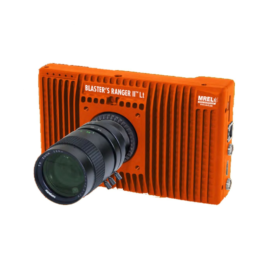
Over view This Chapter describes all of the hardware components provided with the Blaster’s Ranger II™ Lt High Speed Digital Video Camera. 2.1 Blaster’s Ranger II™ Lt High Speed Digital Video Camera Blaster’s Ranger II™ Lt High Speed Digital Video Camera is encased in a rigid steel housing. -
Page 13: Blaster's Ranger Ii™ Lt Accessories
DC power supply with a range of 12-26 VDC 2.2.5 Blaster’s Ranger II™ Lt I/O Cable Blaster’s Ranger II™ Lt I/O Cable is comprised of a total of three connectors: Sync In(blue), Sync Out (green) and Trigger In (red). T: +1-613-545-0466 F: +1-613-542-8029 www.mrel.com... -
Page 14: Blaster's Ranger Ii™ Lt Ac Adapter
2.2.6 Blaster’s Ranger II™ Lt AC Adapter Blaster’s Ranger II™ Lt AC Power Cable will connect to a 110V to 220V power source. 2.2.7 Trigger Switch Cable With Button The trigger cable with switch allows the user to trigger the camera at a distance. The user can extend this cable with the appropriate BNC connectors and a reel of RG-58 coaxial cable. -
Page 15: Chapter 3 Getting Started
Chapter 3 Getting Started T: +1-613-545-0466 F: +1-613-542-8029 www.mrel.com... -
Page 16: Introduction
Over view This chapter provides an outline of how to setup the Blaster’s Ranger II™. This chapter assumes that the User will first want to unpack the Blaster’s Ranger II™ Lt and set it up in an office environment in order to learn the camera controls. 3.1 Introduction This chapter provides a detailed description of the setup procedure for the Lt. -
Page 17: Blaster's Ranger Ii™ Lt Setup
Trigger Switch Cable I/O Cable has 8-pin LEMO camera connector and BNC connectors for Sync-In, Sync-Out, and Trigger-In. The Trigger switch cable is attached to the Trigger-In connector. See Figure 4: I/O Cable and Trigger. T: +1-613-545-0466 F: +1-613-542-8029 www.mrel.com... -
Page 18: Dc Power Connection
3.3.4 DC Power Connection Figure 4: I/O Cable and Trigger The camera can be powered by a 12 V AC/DC adapter or the external 12V DC battery. 3.3.5 Ethernet connection Connect the camera with your laptop, a computer or a network switch using one straight through Ethernet cable. -
Page 19: Chapter 4: Fasmotion
Chapter 4 FasMotion T: +1-613-545-0466 F: +1-613-542-8029 www.mrel.com... -
Page 20: Install Fasmotion Control Software On Pc Or Mac
Before we can begin setting up the camera, you must first install the Fastec FasMotion Controller software. The FasMotion software install program is available on the MREL USB thumb drive that shipped with your camera. With it you may configure all recording parameters... -
Page 21: Language Selection In Fasmotion
Blaster’s Ranger II™ Lt may be configured using the Network Configuration dialog in FasMotion: Click on the camera you wish to manage (do not double-click) to highlight the selection. Right click, Change IP Address...or from Camera...Configuration...Network... T: +1-613-545-0466 F: +1-613-542-8029 www.mrel.com... -
Page 22: Wifi Setup
From this dialog you may select DHCP if you wish for the camera to receive an IP address dynamically from your DHCP server or if you wish for the camera to establish a Local Link Address. Or you may select Static and edit the IP Address, Net Mask, and Gateway to work with your established network, as default: 192.168.1.18. -
Page 23: Fasmotion Application Window
The Default Gamma setting is used to set the default output Gamma for displayed and saved images. The default Gamma is 1.0 (linear). Many laptop computer displays have a Gamma of 1.0, while most larger flat panel LCD monitors have a Gamma of 2.2. T: +1-613-545-0466 F: +1-613-542-8029 www.mrel.com... -
Page 24: Display Rate For Live Images
Note: Changing the Default Gamma setting does not change the current Gamma of the camera, it sets its reset value. To set the Gamma of the camera to a new default, navigate to the Display Settings tab and select “Reset Light and Color Settings.” Two screen shots of a high-contrast image to demonstrate the difference in appearance between Gamma 1.0 and 2.2. -
Page 25: Camera Time And Date
“media,” which contains directories for each mass storage device installed on the camera. 4.10.3 USB OTG: Another option for connecting to the Blaster’s Ranger II™ Lt is via the USB OTG port. T: +1-613-545-0466 F: +1-613-542-8029 www.mrel.com... -
Page 26: Storage Setup
4.11 Storage Setup The FasMotion Storage Settings Tab gives the user access and control of the Camera memory and any installed media, including a Solid State Drive (SSD), SD Card, or USB drive. has 4GB, or 8GB of internal high-speed memory used for capturing high-speed imagery (depending on model Blaster’s Ranger II™... -
Page 27: Configurations
After a Reboot or Power Down, you will need to re-connect the camera to FasMotion by returning to the “Find Cameras” dialog and scanning for the camera after it boots up. See “3-3 Connect the to a Wired Network”. Blaster’s Ranger II™ Lt T: +1-613-545-0466 F: +1-613-542-8029 www.mrel.com... -
Page 28: Camera Information
4.14 Camera Information Camera information is located in the “Find Cameras” window. To open the Find Cameras window, click on the Find Cameras icon in FasMotion. The information fields will populate as soon as you select a camera from the Found Cameras list. Information Included: •... -
Page 29: Chapter 5: Recording
Chapter 5 Recording T: +1-613-545-0466 F: +1-613-542-8029 www.mrel.com... -
Page 30: Long Record And Standard Modes
Over view This chapter provides an outline of how to setup the Blaster’s Ranger II™ Lt for recording, viewing, and saving events. 5.1 Long Record and Standard Modes Ranger II Lt cameras may be operated in either Standard mode or Long Record mode if you bought the Long Record mode upgrade. 5.1.1 Switching from Standard mode to Long Record Mode on the Camera in FasMotion: With the camera in Live, go to Configuration / Preferences. -
Page 31: To Set The Resolution Of The Camera
512 x 512 image (lower right quadrant) would be 740 and 512. 5.3 Setting Shutter Speed The Shutter Speed is expressed in microseconds of exposure time. Minimum Exposure: Minimum exposure is 2msec (regardless of frame rate) T: +1-613-545-0466 F: +1-613-542-8029 www.mrel.com... -
Page 32: Setting The Shutter Speed
Maximum Exposure: The maximum exposure time is dependent on the frame rate. It is always (1/Frame Rate) - 6msec For example, at 500 fps, the maximum exposure is: (1/500 sec) -6msec = 2000msec -6msec = 1994msec For those accustomed to using shutter angle, to convert that to degrees: (Exposure (in msec) / Frame Time) X 360o For example, at 500fps, an exposure time of 250msec is: (250msec / 1/500 sec) X 360o = (250 / 2000) X 360o = 45o... -
Page 33: Setting Bit Depth
Click on the pull-down in the External Trigger box to expose the choices, which are: Rising, Falling, or Disabled. Choose “Rising” for rising signals or a switch opening and “Falling” for a falling signal or switch closure. T: +1-613-545-0466 F: +1-613-542-8029 www.mrel.com... -
Page 34: Configuring Sync And Arm I/O
5.6 Configuring Sync and Arm I/O 5.6.1 IRIG Enable The IRIG option is currently available for Blaster’s Ranger II™ Lt cameras only. If you have an application that requires Blaster’s Ranger II™ with IRIG, please contact Fastec Imaging to explore options. 5.6.2 Enable Sync In / Sync Out Sync In and Sync Out functions are used to synchronize the frame timing of a camera with another device or clock. -
Page 35: Calibrate Black Level
Live Mode (not Recording or Reviewing a recording) either click on the Trigger Button or click on “Snapshot...” in the Camera menu. A dialog box will appear asking where to store the image. Select the storage media you wish to use. (The image will be saved in <storage device>/dcim/100fastc.) T: +1-613-545-0466 F: +1-613-542-8029 www.mrel.com... -
Page 36: Standard Basic Mode Recording
5.8.2 Standard Basic Mode Recording Click the Arm Button. The Arm Button will turn from green to brown and the camera begins recording into its circular buffer. The Camera LED will change from Green (LIve) to slowly flashing Red. It will record for an indefinite period of time until it gets a Trigger. If the Arm Button is pressed a second time, the Recording will abort. -
Page 37: To Set Up Autosave
5.10.2 Cancelling FasFire If you press the Arm button while recording, you will get a warning message asking if you wish to cancel. If you click on T: +1-613-545-0466 F: +1-613-542-8029 www.mrel.com... -
Page 38: Video Review With Multiple Partitions
“OK,” the camera will continue to save images. If you click on Arm and Trigger, the camera will make one more capture and go into Review/Playback. The last recording will be available for Review/Playback and Save, as will any other recordings still in DRAM. 5.10.3 Video Review with Multiple Partitions When there are multiple partitions with unsaved clips in DRAM, the FasMotion Video Review Tab will show the number of available clips. -
Page 39: Reviewing Captured Imagery: Playback
Click on the right or up arrow on the keyboard to move 1 frame forward • Click on Page down to move 10 frames backward • Click on Page up to move 10 frames forward T: +1-613-545-0466 F: +1-613-542-8029 www.mrel.com... -
Page 40: Setting The Start Clip And End Clip Points
• Click on End to move to the end • Click on Home to move to the beginning 5.12.3 Setting the Start Clip and End Clip points: Click on the Pause play button. All buttons should now be active (black). Click and drag the Playback Bug to the frame you wish to be the starting point. -
Page 41: Using The I/O Graph Display
Per Frame Metadata may always be viewed while playing unsaved images in camera memory and also may be viewed when playing back saved image files if they were saved with the XML file. 5.12.11 To View Per Frame Metadata: Select Per Frame Metadata from the View menu while in Review. T: +1-613-545-0466 F: +1-613-542-8029 www.mrel.com... -
Page 42: Image Processing
. If you have an application that requires IRIG on the Blaster’s Ranger II™ Lt , please contact MREL.) Sync: Internal The Sync term can be Internal (internal camera clock used for frame timing), PPF (Sync-In pulse used for per-frame timing), or PPS (1Hz clock input at Sync in used to derive the camera frame timing). -
Page 43: User Control Of Image Processor
Adjust the lens aperture so that the histogram shows the pixel values grouped high (to the right side of the box), but not saturated. It is important that the high pixel value is less than 255. Notice on the example here, that the RGB peaks are not well aligned and T: +1-613-545-0466 F: +1-613-542-8029 www.mrel.com... -
Page 44: Using Rgb Gain Controls
that the Blue peak is farthest to the left. This means that the color is skewed slightly towards the yellow, the complement to blue. Note: The histogram used with Custom White Balance represents only the area of the reticle, not the whole image. Press the Trigger button. - Page 45 Image files may be saved multiple times using different formats, different start and stop points, and different image processing options (brightness, contrast, gamma, color, etc.). If 10-bit images have been captured, imagery may be saved multiple times using different bit-depths. T: +1-613-545-0466 F: +1-613-542-8029 www.mrel.com...
-
Page 46: Transfers, Batch Transfers And Conversions
5.16 Transfers, Batch Transfers and Conversions Stills, stacks, videos, and capture files (CAP), saved on camera media may be managed via Explore on the FasMotion Storage Settings tab. Copy / Batch Copy Stills, videos, and stacks may be copied from any camera media (SD card, SSD, or USB device) to any other camera media or to a Path accessible via your computer (any media attached to your computer or networked drive, etc.). -
Page 47: Chapter 6: Using The Web App
Chapter 6 Using the Web App T: +1-613-545-0466 F: +1-613-542-8029 www.mrel.com... -
Page 48: Web App Overview
Over view This chapter provides an outline of how to use the Web App. 6.1 Web App Over view The Web Application is a utility built into the Blaster’s Ranger II™ Lt which makes control of the camera possible by any networked computer running an Internet Browser. -
Page 49: Storage Settings Tab
Notice that in the example, we are looking at the directory of the SD Card: .../media/sdcard. Click on “hs_video/” to find the stored video files. Click on “dcim/” then “100fastc/ to find stored stills and video stacks. T: +1-613-545-0466 F: +1-613-542-8029 www.mrel.com... -
Page 50: Formatting
To play a video, click on the file name and the video will open in the default media player. Large stored videos may play slowly when opened this way. You may wish to copy them to a computer drive first, and play them from there. To open a still, click on the file name and the still will open in the explore window. -
Page 51: Setting Roi
FPN selection (Disabled / Column FPN / Pixel FPN) can be done from the Web-Application via the Advanced Settings menu. Black Frame Calibration may be done from the Camera Systems section of the Camera tab. T: +1-613-545-0466 F: +1-613-542-8029 www.mrel.com... -
Page 52: Record Controls
6.5 Record Controls The Record Controls Tab of the Web-App with the External Trigger, Sync In and Sync Out pull down menus open. 6.5.1 Setting the Trigger Position: The trigger position is set via slider. There is much finer control of the trigger position using the Web-App than can be had on the camera GUI. External Trigger: Select Rising Edge, or Falling Edge to enable the External Trigger. -
Page 53: Review Tab
Use the “Add a Comment” check box to add a comment to your video. This comment will appear in the camera metadata. Select or deselect “Use Raw Format.” This check box will be active or grayed depending on the bit depth recorded and the file type selected. T: +1-613-545-0466 F: +1-613-542-8029 www.mrel.com... - Page 54 Select the destination drive using the “SD Card,” “SSD,” and “USB Drive” radio buttons. Click on “Save Partition.” A Progress Bar will appear beneath the image window showing the download status. When finished, an information window will appear. Bl as ter ’s R a ng er II Lt Op er a tio ns Ma nua l - E d i t ion 1 .1...
-
Page 55: Chapter 7: Field Operations
Chapter 7 Field Operations T: +1-613-545-0466 F: +1-613-542-8029 www.mrel.com... -
Page 56: Introduction
Combinatory analysis of video data with VOD data or other sensors allows live visualization of issues perceived • Sensor Fusion™ from other data acquisition methods such as those captured by the MREL DataTrap II™ MREL MicroTrap™. The Figure on the following page illustrates the various high speed video photography applications. - Page 57 T: +1-613-545-0466 F: +1-613-542-8029 www.mrel.com...
-
Page 58: Selecting A Camera Position
Make Trigger wrapped over the end of a detonator). If the User intends to trigger the recording manually, the push-button trigger device is available from MREL with any desired length of cabling. Finally, the location should also ensure that during the blast, the first boreholes to fire do not obscure the line of sight of other boreholes. -
Page 59: Power Supply Option
Review Mode. 15. Click on the Live button to put the camera back into Live Mode. From here a new recording can be made or the camera’s configuration can be changed. T: +1-613-545-0466 F: +1-613-542-8029 www.mrel.com... - Page 60 I M P O R T A N T The Blaster’s Ranger II™ Lt Camera image memory is volatile memory and images will be lost if a new recording is initiated or the Blaster’s Ranger II™ Lt Camera is powered off . Be sure to save important videos before initiating a new recording or turning off the Blaster’s Ranger II™...
-
Page 61: Chapter 8: Proanalyst ® Introductor Y Edition Software
Chapter 8 ProAnalyst Introductory ® Edition Software T: +1-613-545-0466 F: +1-613-542-8029 www.mrel.com... -
Page 62: About Proanalyst ® Introductory Edition
32 features. Will allow the User to ® quickly export to Excel or Matlab for further analysis and graphing. If you need to track more than one point at the same time, please contact MREL to upgrade to ProAnalyst Professional Edition. -
Page 63: Image Processing
After the two points are selected, the user can enter the value between the two points selected and then select the units of measurement of the number from the pull down menu. After the units are selected, the Apply Scale >> button MUST be clicked. This will change the box beside the button to xx pixels/“units selected”. T: +1-613-545-0466 F: +1-613-542-8029 www.mrel.com... -
Page 64: Display Layers
The origin of the coordinate system can be set in a similar method. Point the reticle to point were the operator requests the coordinate origin to be (0,0). This will be the reference point for all of the measurements. After the origin is set, the orientation of the axes must be set. - Page 65 8.2.6.1 Show All Display every point created. 8.2.6.2 Show Past Display only past point created in the video. 8.2.6.3 Show Current Display only the current point. 8.2.6.4 Show None This will not display any points. T: +1-613-545-0466 F: +1-613-542-8029 www.mrel.com...
-
Page 66: Under The Tracking Box
8.2.7 Under the Tracking box The buttons from left to right are: Track Backwards, Track One Frame Backwards, Stop, Track One Frame Forward Track Forward. The software takes an image of the Defined Region when the Set Region button is pressed. At some points, the Automatic Tracking loose the item of interest, the user stop the tracking by pressing the middle Tracking button and play the video back (not track... -
Page 67: Explanation Of The Unshaded Cells
The Graphs tab has all of the measurements in a graphical solution. The graph on the left is the final solution produced by MREL to show the user what a completed graph could look like. The two white lines and text boxes were manually generated by hovering the cursor over the graph to record the values. This can be done on the graph on the right. -
Page 68: Example Demonstration File Explanation - Disrupter Example
8.4 Example Demonstration File Explanation – Disrupter Example This Mining example is for the purpose of learning ProAnalyst® Introductory Edition. The example file can be found in the Disrupter_ Demo directory. This example file was captured at 1000 frames per second. The calibration of the video is as shown in the calibration tab with the distance from the edge of the blue container to the third sensor (which is a third of the distance from the tip to the pole) is 5 meters. -
Page 69: Image Processing
The positive orientation of the two axes will be along the edge of the frame. For example, the top left button will set positive X direction to the right and the positive Y direction down while the bottom right button will set the T: +1-613-545-0466 F: +1-613-542-8029 www.mrel.com... -
Page 70: Display Layers
positive X direction to the left and the positive Y direction up. The four buttons around the reticle will set the positive orientation around the button pressed from the reticle position. If the orientation of the X axis is not horizontal, from the origin of the coordinate system place the reticle on the horizontal line and then click Set X Direction. -
Page 71: Under The Tracking Box
Region. The operator can then continue the track in the same direction (forward or backwards) and the previously tracked points will move to the new location. T: +1-613-545-0466 F: +1-613-542-8029 www.mrel.com... -
Page 72: Save All Toolkits
Once the object is tracked, the lock between the eye and the wrench should then be closed (to the locked position) to avoid and changes to the points. Units & Export section will allow the user to select the units to export the data to as well as the form that the file will be. In this example, the setup was Meters and Text. - Page 73 (-1) because the coordinate system was defined with Positive X to the right, the left side positive motion is to the left. The other solution is to define another calibration for the Left_Side measurement. All of the other measurements are as described above. The Graphs tab has all of the measurements in a graphical solution. T: +1-613-545-0466 F: +1-613-542-8029 www.mrel.com...
- Page 74 Bl as ter ’s R a ng er II Lt Op er a tio ns Ma nua l - E d i t ion 1 .1...
-
Page 75: Chapter 9: Contacting Mrel For Technical Support
Chapter 9 Contacting MREL for Technical Support T: +1-613-545-0466 F: +1-613-542-8029 www.mrel.com... -
Page 76: Contacting Mrel
Tel: +1-613-545-0466 Fax: +1-613-542-8029 support@mrel.com Email: MREL looks forward to providing you with assistance. Bl as ter ’s R a ng er II Lt Op er a tio ns Ma nua l - E d i t ion 1 .1... - Page 77 T: +1-613-545-0466 F: +1-613-542-8029 www.mrel.com...
- Page 78 MREL is committed to product innovation; accordingly product may undergo specification improvements without notice. Copyright © 2016 MREL Group of Companies Limited. Blaster’s Ranger II™ Lt High Speed Camera, Blaster’s Ranger II™ Lt High Speed Camera Logo, and MREL Logo are trademarks or registered trademarks of MREL Group of Companies Limited.
Need help?
Do you have a question about the Blaster’s Ranger II Lt and is the answer not in the manual?
Questions and answers