
Related Manuals for PENKO 1020


Summary of Contents for PENKO 1020
- Page 1 PENKO Engineering BV The Leading Experts In Weighing & Dosing 1020 Indicator Manual For more information visit www.penko.com - technical support - literature library...
- Page 2 If this Instruction Manual is not the processes. The use of non-specified ‘look- correct manual for the Penko product you alike’ substitution parts may result in the are using, call 0031(0)318-525630 for a risk of fire, electrical hazards, or improper replacement copy.
- Page 3 Proper relay use and configuration is the responsibility of the user. Do not operate this instrument without the front cover being secured. Refer any installation, operation or servicing issues to qualified personnel. WWW.PENKO.COM Penko is an ETC Company e-mail: info@penko.com...
-
Page 4: Table Of Contents
1020 Indicator TABLE OF CONTENT Chapter Page 1. Indication of display 2. Screen Elements 3. Explanation of front keys 3. Load cell / power connection 4. First use of Indicator 4.1. Weigher Setting 4.2. Calibration Setting 5. Menu Setting 5.1. System Settings 5.1.1. - Page 5 1020 Indicator TABLE OF CONTENT Chapter Page 10. Profibus Protocol Description 11. Standard Factory Settings Appendix I Appendix II Appendix III...
-
Page 6: Indication Of Display
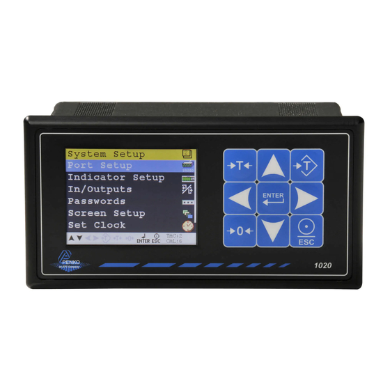
1020 Indicator 1. Indication of Display 1. Zero active 5. Value 2. Tare active 6. Range active 3. Weigher stable 7. Bargraph 4. Inputs 8. Outputs 2. Screen Elements 1. Active keys 3. Traceable Acces Code 2. Menu level 4. Calibration Code... -
Page 7: Explanation Of Front Keys
1020 Indicator 2. Explanation of front keys Tare Check the NET sign (See page 5, Indication of Display, number 2) if there is a tare active. Press key to set tare. Press key again to reset tare. Preset Tare Check the NET sign (See page 5, Indication of Display, number 2) if there is a tare active. -
Page 8: Load Cell / Power Connection
1020 Indicator 3. Load cell / power connection Outputs Outputs PENKO 1020 Basic Inputs Inputs The power cable must be looped through a ferrite core 3 times. Recommended ferrite core: Würth Elektronik 7427154 Option Supply 18 - 32 Vdc Power connection... - Page 9 1020 Indicator 3. Load cell / power connection -continue- Outputs PENKO 1020 Profibus Inputs The power cable must be looped through a ferrite core 3 times. Recommended ferrite core: Würth Elektronik 7427154 Option Supply 18 - 32 Vdc Power connection...
- Page 10 1020 Indicator 3. Load cell / power connection PENKO 1020 Profibus Profibus connection wiring PIN No. Symbol Name Name SHIELD SHIELD Protective Ground Reserved for Power Rxd/TxD-P Receive/Transmit-Data-P CNTR-P Control-P DGND Data Ground Voltage plus Reserved for Power RxD/Txd-N Receive/Transmit-Data-N...
- Page 11 1020 Indicator 3. Load cell / power connection -continue- Outputs PENKO 1020 RS232/RS422 Inputs The power cable must be looped through a ferrite core 3 times. Recommended ferrite core: Würth Elektronik 7427154 Option Supply 18 - 32 Vdc Power connection...
- Page 12 1020 Indicator 3. Load cell / power connection -continue- PENKO 1020 RS232 This product is intended to be supplied by a Class 2 or Limited Power Source, rate 18 - 32 Vdc, 0.4A@24Vdc. Connection example of a printer through RS232 communication.
- Page 13 1020 Indicator 3. Load cell / power connection -continue- PENKO 1020 RS422 This product is intended to be supplied by a Class 2 or Limited Power Source, rate 18 - 32 Vdc, 0.4A@24Vdc. Example of communication through RS422 for multiple devices using PV protocol.
- Page 14 1020 Indicator 3. Load cell / power connection -continue- PENKO 1020 CANBUS Outputs H = CAN_HIGH Inputs The power cable RTN = GROUND must be looped L = CAN_LOW through a ferrite SH = SHIELD core 3 times. Only works with PENKO...
-
Page 15: First Use Of Indicator
1020 Indicator 4. First use of indicator Make the indicator ready for its first use. 4.1. First use of indicator -Weigher Settings- Set up the correct indicator setting (step size, decimal point position and maxload). The start Turn the indicator on by connecting it to the power supply. - Page 16 1020 Indicator 4.1. First use of indicator -Weigher Settings - continue- Use the DOWN key to select Indicator Setup and press Enter Entering the TAC number Select Indicator and press Enter Enter TAC (number) by using the UP key and confirm with Enter TAC (Traceable Access Code) shows on lower right of the screen.
- Page 17 1020 Indicator 4.1. First use of indicator -Weigher Settings - continue- Step size Select Weigher and press Enter Use the DOWN key to select Step and confirm with Enter The step size defines the scaled parts of the weight value. The display value will be rounded off to the nearest value with a valid step size.
- Page 18 1020 Indicator 4.1. First use of indicator -Weigher Settings - continue- Use the UP and DOWN key to select the correct step size and confirm with Enter Decimal point position Use the DOWN key to select Decimal point and press Enter The decimal point defines the point of decimal of the weight value.
- Page 19 1020 Indicator 4.1. First use of indicator -Weigher Settings - continue- Maxload Use the DOWN key to select Maxload and press Enter. The max load prevents overload by user. Any weight above this set value will not be shown. If there is an overload, display shows the error code ======.
-
Page 20: Calibration Setting
1020 Indicator 4.2. First use of indicator -Calibration- Calibration settings are used to check, delete and set calibration points. First, enter the Indicator Setup menu as decribed on page 14, and press the DOWN key to go to Calibration and press Enter. If you are already in the Indicator Setup menu, use the DOWN key to go to Calibration and press Enter. - Page 21 1020 Indicator 4.2. First use of indicator -Calibration - continue- Setting calibration points Use the DOWN key to select Calibration and press Enter Select dual point and press Enter Before you proceed, make sure the weigher is unloaded. First calibrate the zero point with the unloaded weigher by pressing Enter...
- Page 22 1020 Indicator 4.2. First use of indicator -Calibration - continue- For setting the second calibration point a reference value is needed. For this example, an actual reference weight of 20 kg was used. Use the DOWN key to select the second calibration point and press Enter.
-
Page 23: Menu Setting
1020 Indicator 5. Menu Settings Press ENTER for more than 2 seconds to get in to Main Menu screen > 2 s The main menu options are: System Setup, Totals, Info and Certified Info. To enter one of the menu options, select the correct option with the UP or DOWN key and press Enter 5.1. -
Page 24: Port Setup
1020 Indicator 5.1.1. Menu Settings - System Setup - Port Setup- Scroll through the menu options by using the UP or DOWN key and press Enter to select the chosen option. Port Setup In this menu, all communication ports and protocols can be set. The options are Ethernet Setup, RS232 Port, RS422 Port, CAN Port and Profibus Setup. - Page 25 Settings in the Ethernet Setup menu ASCII over Ethernet Starting at firmware version 1.4.0.9.0.5 Edit the Ethernet IP number. the PENKO ASCII protocol is available over TCP at port 23. This feature is automatically enabled when both Edit the Ethernet Subnet IPmask.
- Page 26 1020 Indicator 5.1.1. Menu Settings -System Setup - Port Setup - continue- RS232 Port In this menu, all settings for the RS232 comport can be set. Scroll through the RS232 Port menu using the UP or DOWN key. Press Enter for editing the setting.
- Page 27 1020 Indicator 5.1.1. Menu Settings -System Setup - Port Setup - continue- Select a parity for the protocol. Choose between None, Odd, Even, Mark and Space. Select a speed for the protocol. Choose between 1200, 2400, 4800, 9600, 19200, 38400, 57600 and 115200 pbs.
- Page 28 1020 Indicator 5.1.1. Menu Settings -System Setup - Port Setup - continue- Settings in the RS422 menu Select the communication protocol. Choose between None, Printer, ASCII, NPV Slave, Modbus RTU and Modbus ASCII. Select an address to identify the device in a configuration with multiple devices.
- Page 29 1020 Indicator 5.1.1. Menu Settings -System Setup - Port Setup - continue- CAN Port In this menu, all settings for the CAN comport can be set. Scroll through the CAN Port menu using the UP or DOWN key. Press Enter for editing the setting.
- Page 30 1020 Indicator 5.1.1. Menu Settings -System Setup - Port Setup - continue- Select a speed of the protocol. Choose between 100, 125, 250 and 500 kbps. Profibus Setup - Only available when Profibus option board is installed. In this menu, all settings for the Profibus comport can be set.
-
Page 31: Indicator Setup
1020 Indicator 5.1.2. Menu Settings -System Setup - Indicator Setup- Indicator Setup The Indicator Setup options are Indicator, Calibration and Recall. Scroll through the menu options by using the UP or DOWN key and press Enter to select the chosen option. - Page 32 1020 Indicator 5.1.2. Menu Settings -System Setup - Indicator Setup - continue- Enter TAC (number) by using the UP key and confirm with Enter TAC (Traceable Access Code) shows on lower right of the screen. Every time settings are changed, the TAC automatically levels up by 1.
- Page 33 Scroll through the Weigher menu using the UP or DOWN key. Press Enter for editing the setting. Settings in the Weigher menu Give the PENKO 1020 a unique name within the application so it’s easy to recog- nize in the process or in the factory. Define the unit of measurement.
- Page 34 Note: In certified mode the zero band = 4% (+2 and –2%). Also zero suppressing is disabled. Set maximum load to prevent overload by user. The PENKO 1020 will not show any weight above the set value. Choose a weight between -8388608 and +8388607.
- Page 35 5.1.2. Menu Settings -System Setup - Indicator Setup - continue- Stable condition The PENKO 1020 will give a stable signal when the weigher value is stable within the set range and time. Scroll through the Weigher menu using the UP or DOWN key. Press Enter for editing the setting.
- Page 36 1020 Indicator 5.1.2. Menu Settings -System Setup - Indicator Setup - continue- Zero tracking Zero tracking is able to tune the zero point back to zero when the scale becomes dirty. Scroll through the Zero tracking menu using the UP or DOWN key. Press Enter for editing the setting.
- Page 37 1020 Indicator 5.1.2. Menu Settings -System Setup - Indicator Setup - continue- Range/Interval Set the indicator to change its step size when the weigher signal reaches a certain value. Scroll through the Range/Interval menu using the UP or DOWN key. Press Enter for editing the setting.
- Page 38 1020 Indicator 5.1.2. Menu Settings -System Setup - Indicator Setup - continue- Example Max Step: Displayed range Step size If the settings are: Step size = 1, Range = 100 and Max. 0-100 Step = 50, the table on the right shows the...
- Page 39 1020 Indicator 5.1.2. Menu Settings -System Setup - Indicator Setup - continue- Filter Filters are used because of the vibrations present in an industrial environment. Scroll through the Filter menu using the UP or DOWN key. Press Enter for editing the setting.
- Page 40 1020 Indicator 5.1.2. Menu Settings -System Setup - Indicator Setup - continue- Scroll through the Filter menu using the UP or DOWN key. Press Enter for editing the setting. Settings in the Filter– Digital Menu Choose between None, Dynamic Application and Static Application.
- Page 41 1020 Indicator 5.1.2 Menu Settings -System Setup - Indicator Setup - continue- Scroll through the Filter menu using the UP or DOWN key. Press Enter for editing the setting. Settings in the Filter - Display Menu Set the band where the filter is active. Choose a weight between –8338608 and 8668608.
- Page 42 1020 Indicator 5.1.2. Menu Settings -System Setup - Indicator Setup - continue- Calibration In this menu, the calibration can be set. Enter the CAL code to enter the menu. Entering the CAL number Select Calibration and press Enter Enter CAL (number) by using the UP key and confirm with Enter.
- Page 43 1020 Indicator 5.1.2. Menu Settings -System Setup - Indicator Setup - continue- The calibration menu is now visible: The calibration menu options are Show, Calibrate, Deadload, Geo-CAL and Range. Scroll through the menu options by using the UP and DOWN keu and press Enter to select the chosen option.
- Page 44 1020 Indicator 5.1.2. Menu Settings -System Setup - Indicator Setup - continue- CAL: ‘Calibration code’ is the number of times the calibration is changed. When an indicator gets certified, this number will be written on the device and is used by the controlling agency to see if the settings aren’t changed after sealing.
- Page 45 1020 Indicator 5.1.2. Menu Settings -System Setup - Indicator Setup - continue- Dual Point A calibration with 2 points. See page 11,12 and 13 for calibration instructions. Multi Point A calibration with more than 2 point. Calibration upto 10 points is possible. Multi point calibration is mostly used if the weigher signal is not linear.
- Page 46 1020 Indicator 5.1.2. Menu Settings -System Setup - Indicator Setup - continue- Select the ‘to be deleted’ calibration point by using the UP or DOWN key, press 0 to remove the calibration points and confirm by Enter. Confirm deletion by Enter of cancel deletion by ESC.
- Page 47 Make sure the weigher is unloaded and press Enter. Calibration second or higher calibration point: An actual reference value is needed. For this example, a reference value of 1020 kg was used. Use the UP, DOWN and LEFT key to enter the reference value. The UP and DOWN keys are used for changing the number (1-9), the LEFT key is used for changing the position of the cursor.
- Page 48 1020 Indicator 5.1.2. Menu Settings -System Setup - Indicator Setup - continue- Repeat the process from Calibration second or higher calibration point for each extra calibration point. Press the Esc key six times to go back to the main screen.
- Page 49 1020 Indicator 5.1.2. Menu Settings -System Setup - Indicator Setup - continue- The Max. Load value will be provided by the supplier of the load cells. Enter the type of load cells. Deadload In this menu, the deadload can be set to pull the whole weighing line back to zero.
- Page 50 1020 Indicator 5.1.2 Menu Settings -System Setup - Indicator Setup - continue- Normally, the deadload is zero, but it is possible to change the line position if there is weight on the scale. To do so, edit the actual weigh value to the new known value.
- Page 51 1020 Indicator 5.1.2 Menu Settings -System Setup - Indicator Setup - continue- Settings in the Geo-CAL menu Edit the Latitude and Elevation of the place of fabrication of the load cells. Scroll through the Geo-CAL menu using the UP or DOWN key. Press Enter for editing the setting.
- Page 52 1020 Indicator 5.1.2 Menu Settings -System Setup - Indicator Setup - continue- Edit the Latitude and Elevation of the place of installation. Scroll through the Geo-CAL menu using the UP or DOWN key. Press Enter for editing the setting. Settings in the Geo-CAL - Install Location menu Enter the geographical latitude of the place of installation.
- Page 53 1020 Indicator 5.1.2 Menu Settings -System Setup - Indicator Setup - continue- Range In this menu the range for the load cells input can be set. Enter the Range menu by pressing Enter of leave the menu by pressing ESC.
- Page 54 Set an ADC value offset. This can be used when the weigher gets out of its ADC range. Choose a value between –500000 and +500000. For more information, contact PENKO. Recall This menu allows to set all indicator parameter back to factory settings.
-
Page 55: In/Outputs
Scroll through the In/Outputs menu using the UP or DOWN key. Press Enter for editing the setting. Inputs In this menu, the inputs can be set. The PENKO 1020 has 3 digital inputs. All in- puts can be configured as different functions. - Page 56 For explanation of the options, see appendix II. Outputs/Levels In this menu, the outputs can be set. The PENKO 1020 has 4 digital outputs. Scroll through the Outputs/Levels menu using the UP or DOWN key. Press Enter for editing the setting.
- Page 57 1020 Indicator 5.1.3. Menu Settings -System Setup - In/Outputs - continue- Settings in the Outputs/Levels menu Select the output. Choose between 1, 2, 3 and 4. Select the weigher mode the output has to switch on. For explanation of the op- tions, see appendix III.
- Page 58 1020 Indicator 5.1.3. Menu Settings -System Setup - In/Outputs - continue- Positive hysteresis Negative hysteresis...
- Page 59 1020 Indicator 5.1.3. Menu Settings -System Setup - In/Outputs - continue- DAC Setup In this menu, all DAC parameters can be set. Scroll through the DAC Setup menu using the UP or DOWN key. Press Enter for editing the setting.
- Page 60 In this menu, the DAC can be calibrated using a mA meter. Calibration: Connect the mA meter to the DAC output. The output of the 1020 is set to 0mA and press Enter to continue Use the UP, DOWN and LEFT key to enter the reference value. The UP and DOWN keys are used for changing the number (1-9), the LEFT key is used for changing the position of the cursor.
- Page 61 1020 Indicator 5.1.3. Menu Settings -System Setup - In/Outputs - continue- The output 1020 is set to 24mA. Press Enter to continue. Use the UP, DOWN and LEFT key to enter the reference value. The UP and DOWN keys are used for changing the number (1-9), the LEFT key is used for changing the position of the cursor.
-
Page 62: Password
1020 Indicator 5.1.4. Menu Settings -System Setup - Password- Setting in the DAC Test menu Sets the DAC output to the minimum value. Enter a percentage of the DAC output level. Sets the DAC output to the maximum value. Password In this menu, a password to block access to certain parts of the menu can be set. - Page 63 1020 Indicator 5.1.4. Menu Settings -System Setup - Password - continue- If different characters are required, press the Preset Tare key. Additional character set are: Passwords A password for certain parts of the menu can be set. Scroll through the Passwords menu using the UP or DOWN key. Press Enter for...
- Page 64 1020 Indicator 5.1.4. Menu Settings -System Setup - Password - continue- Setting in the Password menu Set a password for System Setup. This will block all menu items Use the UP, DOWN, LEFT and RIGHT key to enter the password. The UP and DOWN keys are used for changing from line, the LEFT and RIGHT key is used for changing the position of the cursor within the line.
-
Page 65: Screen Setup
1020 Indicator 5.1.5. Menu Settings -System Setup - Screen Setup- Screen Setup In this menu, all screen options, button options, language and buzzer can be set. Scroll through the Screen Setup menu using the UP or DOWN key. Press Enter for editing the setting. - Page 66 1020 Indicator 5.1.5. Menu Settings -System Setup - Screen Setup - continue- Settings in the Buttons menu For these 5 keys, the extra functions to chose from are the same. For explanation of the options, see appendix II. Turn the Zero key on or off.
- Page 67 1020 Indicator 5.1.5. Menu Settings -System Setup - Screen Setup - continue- Led Bar In this menu, the bargraph can be set. Scroll through the Led Bar menu using the UP or DOWN key. Press Enter for editing the setting.
- Page 68 1020 Indicator 5.1.5. Menu Settings -System Setup - Screen Setup - continue- Bar Reversed Dot Reversed Set the minimum value of the bar. Choose a weight between -8388608 and +8388607. Set the lower margin of the bar. Choose a value between -8388608 and +8388607.
- Page 69 1020 Indicator 5.1.5. Menu Settings -System Setup - Screen Setup - continue- Screen options In this menu, the all screen options can be set. Scroll through the Screen options menu using the UP or DOWN key. Press Enter for editing the setting.
-
Page 70: Set Clock
1020 Indicator 5.1.6. Menu Settings -System Setup - Set Clock- Select the type of indicator that is displayed on the screen. For explanation of the options, see appendix III. Set Clock In this menu, date and time can be set. -
Page 71: Printer
1020 Indicator 5.1.7. Menu Settings -System Setup - Printer- Set date (dd-mm-yy). Use the UP, DOWN, LEFT and RIGHT key to set the time. The UP and DOWN keys are used for changing the value, the LEFT and RIGHT key is used for chan- ging the position of the cursor. - Page 72 1020 Indicator 5.1.7. Menu Settings -System Setup - Printer - continue- Printer Settings In this menu, the printers settings can be set. Scroll through the Printer Settings menu using the UP or DOWN key. Press Enter for editing the setting.
- Page 73 1020 Indicator 5.1.7. Menu Settings -System Setup - Printer - continue- Set the number of colums. Choose a number between 0 and 80. Set the number of rows. Choose a number between 0 and 80. Set the margin. Choose a number between 0 and 80.
- Page 74 1020 Indicator 5.1.7. Menu Settings -System Setup - Printer - continue- Setting in the Header menu For Line 1, 2, 3 and 4 enter the desired printer header. Maximum number of chartacters per line: 32. Use the UP, DOWN, LEFT and RIGHT key to enter the header. The UP and DOWN keys are used for changing from line, the LEFT and RIGHT key is used for changing the position of the cursor within the line.
- Page 75 1020 Indicator 5.1.7. Menu Settings -System Setup - Printer - continue- Footer In this menu, the footers for the printer ticket can be set. In total, 4 footers for printer tickets can be set. Setting in the Footer menu For Line 1, 2, 3 and 4 enter the desired printer footer. Maximum number of cha- racters per line: 32 Use the UP, DOWN, LEFT and RIGHT key to enter the footer.
- Page 76 1020 Indicator 5.1.7. Menu Settings -System Setup - Printer - continue- Ethernet Printing In this menu, the ethernet printer can be connected. Settings in the Ethernet printing menu Set IP number for ethernet printer. Use the UP, DOWN, LEFT and RIGHT key to set the time. The UP and DOWN keys are used for changing the value, the LEFT and RIGHT key is used for chan- ging the position of the cursor.
-
Page 77: System Recall
Starting at firmware version 1.5.0.9.0.3 a backup of the device configuration can be made within the device. A password is required for the backup. Contact PENKO for this password. When using Pi Mach II manage to make a backup, first enter this password in the... - Page 78 1020 Indicator 5.1.8. Menu Settings -System Setup - Software Recall - continue- Confirm the backup: Restore Parameters only restores the non-certified parameters. Restore Full restores all parameters. The device restarts after a restore action.
-
Page 79: Software Update
This menu sets the PENKO 1020 in USB update mode. Continue by pressing Enter or leave the menu by pressing ESC. The PENKO 1020 can be updated through ethernet and through USB. Only use PIP files, Penko Image Package, for firmware updates! Ethernet Connect the PENKO 1020 to the computer through ethernet. - Page 80 Click ‘Firmware update’ to start the update. The PENKO 1020 will automatically reboot and the ‘Firmware Update Manager’ wil show ‘Updated’. Connect the PENKO 1020 to the computer through USB. Start PI Mach II. Start the Firmware Update Manager. Click ‘Open’ and select the PIP file.
- Page 81 Use double click or the arrow button to put the address in the ‘Destination List’ and click ‘OK’. Now set the PENKO 1020 in update mode. Click ‘Firmware update’ to start the update. The PENKO 1020 will automatically reboot and the ‘Firmware Update Manager’ wil show ‘Updated’.
-
Page 82: Totals
1020 Indicator 5.2. Menu Settings -Totals- Totals From the main screen, press Enter to get into the Totals menu. The selected totals values will be printed on the selected printer when pressed Enter. The Totals options are Subtotal, Total, Day Total and Batch Total. -
Page 83: Info
1020 Indicator 5.3. Menu Settings -Info- Info From the main screen, press Enter to get into the Info menu. The hardware and software information of the device is shown. The Info options are Software Version, MAC Address, Licence, Display Version, Bootloader Version, HWID and SWID. - Page 84 Shows the serial number of the PENKO 1020. Shows the MAC address of the Ethernet chip. Shows what kind of licence the PENKO 1020 has. Shows the display software version. Shows the bootloader software version. Shows the version of the ciurcuit boards of the PENKO 1020.
-
Page 85: Certified Info
Certified Info From the main screen, press Enter to get into the Certified Info menu. The certified information for when the PENKO 1020 is used as a certified weigher is shown. The Certified Info options are Version, Date and Time, CRC Checksum and... - Page 86 Settings in the Certified Info menu Shows the certified version. Shows when the PENKO 1020 was set to certified mode. Shows the checksum on the program. Shows the number of times a new firmware update to the PENKO 1020 is done.
-
Page 87: Event Log
1020 Indicator 5.5. Menu Settings -Event Log- From the main screen, press Enter to get into the Event Log menu. The Event Log shows all logged systems event. This function is only availabe from firmware version 1.3.7.9.0.1 and hardware revision 2. - Page 88 1020 Indicator 5.5. Menu Settings -Event Log- continue Use the UP, DOWN, LEFT and RIGHT key to enter the From Date. The UP and DOWN keys are used for changing the value, the LEFT and RIGHT key is used for changing the position of the cursor. Confirm the From Date with Enter.
- Page 89 1020 Indicator 5.5. Menu Settings -Event Log- continue Selects all filters in the Event Log menu (From Date, To Date and UID). Example of an Event Log: Use the UP, DOWN, key to move through the Event Log entries. The white bar or dot on the right side of the screen shows the position of the cursor in the log.
- Page 90 1020 Indicator 5.5. Menu Settings -Event Log- continue Example of Event Log printer layout: Device: 1020 Serial Number FFFFFFFF Date : 29-01-14 Time : 14:05:38 Event Log Number UID Code Date/Value Time/Unit 1 3591503872 TAC Changed 16-01-14 14:46:14 2 3053060097 Events Cleared...
-
Page 91: Alibi Memory
1020 Indicator 5.6. Menu Settings -Alibi Memory- This function is only availabe from firmware version 1.3.7.9.0.1 and hardware revision 2. Generation of Alibi records Select Alibi memory in the Printer Setting for the System Setup - Printer menu (page 72) and press ENTER Alibi memory menu From the main screen, press Enter to get into the Alibi memory menu. - Page 92 1020 Indicator 5.6. Menu Settings -Alibi Memory- continue The Alibi memory filters are From Date, To Date, UID and All. Scroll through the menu options by using the UP or DOWN key. Settings in the Event Log menu Set the starting date for the Alibi memory.
- Page 93 1020 Indicator 5.6. Menu Settings -Alibi memory- continue Set the Unique Identifier (UID) code for the Event Log. To make each record uni- que, a UID is used. Use the UP, DOWN, LEFT and RIGHT key to enter the UID code. The UP and DOWN keys are used for changing the value, the LEFT and RIGHT key is used for changing the position of the cursor.
- Page 94 1020 Indicator 5.6. Menu Settings -Alibi Memory- continue Example of an Alibi memory, stored gross weight: Use the UP, DOWN, key to move through the Alibi memory entries. The white bar or dot on the right side of the screen shows the position of the cursor in the log.
- Page 95 1020 Indicator 5.6. Menu Settings -Alibi Memory- continue To clear het Alibi memory, press ZERO > 2 s. This will only work when the filter is set to All. An Alibi cleared event is added to the Event Log > 2 s The following screen will be visible: Press ENTER to continue, press ESC to return to the Alibi memory log screen.
-
Page 96: Software Tool
Start PI Mach II and slect Ethernet in the ‘Environment’ menu. Enter the IP address of the PENKO 1020. Click the button next to the address to ping the connection. NOTE: The IP Address must be in the PC range or it will not start to communicate. -
Page 97: Dimensions
1020 Indicator 7. Dimensions Panel Mount version Top view Side view... - Page 98 1020 Indicator 7. Dimensions Stainless Steel version Front view Use appropriate bracket mounting screws with a total minimum strength of 6,8kg Side view...
-
Page 99: Error Codes
1020 Indicator 8. Error Codes Error Code Description Solution 2001 Parameter error Invalid entry, choose a valid value Invalid entry, choose value within 2005 Input value is not valid range Wait for stable weigher signal and try 2101 Weigher not stable... -
Page 100: Weigher Error Codes
1020 Indicator 8.1. Weigher Error Codes Error Code Description Solution CCCCCC No proper calibration available Check calibration setting Check loadcell UUUUUU Underflow Check platform construction Check loadcell OOOOOO Overflow Check platform construction Display overflow; ====== Exceed maximum display Reduce load on platform... -
Page 101: Profibus Protocol Description
1020 Indicator 10. Profibus Protocol Description Note that the GSD Profibus file for the 1020 Indicator differ from 1020 controller GSD file. Use 1020.GSD.File This file is available in the Penko Suite. Inputs to PLC D word 32 bit Weight register... -
Page 102: Standard Factory Settings
1020 Indicator 11. Standard Factory Setting Description Display Value Your setting Weigher Name Unit label Step Decimal Point 0,000 Operation Mode Industrial Max Load 10,0009 Stable condition Range 0,002 Time 1,00 s Zero tracking Range 0,000 kg Step 0,000 kg... -
Page 103: Appendix I
1020 Indicator Appendix I Setting Indicator type Weight Fast Gross Fast Net Display Gross Display Net Tare Peak Valley Hold Weight x 10 Fast Gross x 10 Fast Net x 10 Display Gross x 10 Display Net x 10 Tare x 10... -
Page 104: Appendix Ii
1020 Indicator Appendix II Description Definition None No extra function Zeroset Set to zero Zeroreset Undo set to zero Tareset Set tare Tarereset Undo set tare Tare Toggle Switch between tare & net and vice versa Preset Tare on Automatic tare on configured weight... -
Page 105: Appendix Iii
1020 Indicator Appendix III Description Definition Weight filtered net weigher value that can react on mulit range/interval Fast Gross unfiltered gross weigher value Fast Net unfiltered net weigher value Display Gross filtered gross weigher value Display Net filtered net weigher value... - Page 106 PENKO Engineering B.V. | Schutterweg 35, 6718 XC Ede | The Netherlands | Tel 0031 (0)318 525630 | Fax 0031 (0)318 529715 | info@penko.com | www.penko.com All product information and specifications are subject to change without prior notice. Copyright © 2015...
Need help?
Do you have a question about the 1020 and is the answer not in the manual?
Questions and answers
إضاءة الليدات انطفئت