
Related Manuals for Lombardini LGA 280 OHC Series


Summary of Contents for Lombardini LGA 280 OHC Series
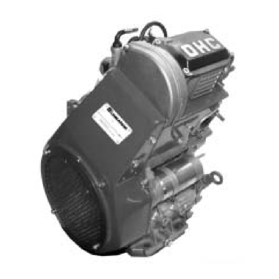
- Page 1 WORK SHOP MANUAL LGA 280 OHC Series engines,code 1-5302-714 LGA 280 OHC 1nd Edition COMPILER TECO/ATI MODEL N° DATE OF ISSUE REG. CODE DATE ENDORSED REVISION 1-5302-714 51130 15.01.2006 15.01.2006...
-
Page 3: General Service Manual Notes
The information contained within this service manual is the sole property of Lombardini. As such, no reproduction or replication in whole or part is allowed without the express written permission of Lombardini. -
Page 4: Table Of Contents
INDEX This manual gives the main instructions on how to repair LOMBARDINI LGA 280 gasoline- fuelled engines, updated as of January 15, 2006. INDEX TROUBLE SHOOTING ____________________________________________________________ Page 7 WARNING SIGNS - SAFETY INSTRUCTIONS ____________________________________________ 8-9 ENGINE IDENTIFICATION _____________________________________________________________ 10... - Page 5 INDEX Cylinder head ..................................35 Disassembly of camshaft timing synchronous belt ......................22 Driving shaft - Check ................................ 42 Driving shaft timing synchronous belt ..........................23 Engine oil - Change ................................18 Engine oil - Refilling ................................18 Engine preparation ................................19 External cover of the lower toothed timing belt - Assembly ....................
- Page 6 INDEX Timing system: camshaft synchronous pulley ........................ 50 Timing system: crankshaft synchronous pulley ......................51 Valve clearance adjusting pads - Correct assembling order ..................33 Valve guides - Assembly ..............................37 Valve guides - Check ................................ 36 Valve guides - Removal ..............................37 Valve guides –...
-
Page 7: Trouble Shooting
TROUBLE SHOOTING TROUBLE SHOOTING Listed below are some of the possible causes of engine operating defects. Carry out simple tests before proceeding with disassembly operations or making substitutions. TROUBLE POSSIBLE CAUSES Grounded sparking plug Disconnected or broken spark cable Faulty coil Faulty rotor Loosened or oxidized cable clamp... -
Page 8: Warning Signs - Safety Instructions
SAFETY INSTRUCTIONS • Lombardini engines are built to provide safe and longlasting performances, but in order to obtain these results it is essential that the maintenance requirements described in the manual are observed along with the following safety recommendations. - Page 9 Check the belt tension only when the engine is turned off. • In order to move the engine use exclusively the eyebolts fitted for this purpose by Lombardini. These lifting points are however not suitable for the entire machine, so in this case use the eyebolts fitted by the manufacturer.
-
Page 10: Engine Identification
ENGINE IDENTIFICATION LGA 280 SPECIFICATIONS Type of engine : Endothermic engine - 8 and 4-stroke cycle - OHC driven by toothed belt, timing synchronized throught toothed belt - Forced-air cooling system with fan flywheel - Lubrication system: fully forced by trochoidal pump - Electrical starting with motor (1,1 kW) - Centrifugal decompression device - Cast iron liner incorporated in the casting... -
Page 11: Technical Features
TECHNICAL FEATURES TECHNICAL FEATURES LGA 280 OHC LGA 280 LGA 280 LGA 280 ENGINE TYPE GASOLINE Cylinder Bore Stroke Displacement Cm³ Compression ratio 8 ÷ 1 8 ÷ 1 8 ÷ 1 Max R.P.M. at no-load 6200 6200 6200 Rating kW N DIN 70020 6,2@4400 5,5@4400 6,4@4400... -
Page 12: Characteristics
Max. power tolerance is 5%. Power decreases by approximately 1% every 100 m di altitude and by 2% every 5°C above 20°C. Note: Consult LOMBARDINI for power, torque curves at rates differing from those given above. COMPILER TECO/ATL REG. CODE MODEL N°... - Page 13 Max. power tolerance is 5%. Power decreases by approximately 1% every 100 m di altitude and by 2% every 5°C above 20°C. Note: Consult LOMBARDINI for power, torque curves at rates differing from those given above. COMPILER TECO/ATL MODEL N°...
-
Page 14: Overall Dimension
OVERALL DIMENSIONS - OPTIONAL P.T.O. AND FLANGES OVERALL DIMENSIONS Note: The values are given in mm COMPILER TECO/ATL REG. CODE MODEL N° DATE DATE OF ISSUE ENDORSED REVISION 1-5302-714 51130 15.01.2006 15.01.2006... -
Page 15: Maintenance - Recommended Oil Type - Refilling
MAINTENANCE - RECOMMENDED OIL - FUELS AND LUBRICANTS Failure to carry out the operations described in the table may lead to technical damage to the machine and/or system MAINTENANCE EXTRAORDINARY AFTER THE FIRST 1.000 Km Engine oil replacement. Oil filter replacement. ORDINARY MAINTENANCE FOR ENGINES LGA 280 OHC FREQUENCY x 1.000 Km ELEMENT... - Page 16 MAINTENANCE - RECOMMENDED OIL - FUELS AND LUBRICANTS FUEL Use PREMIUM gasoline or UNLEADED PREMIUM gasoline of the type used in cars. Use of other types of fuel could damage the engine. The octane rating of the fuel must be higher than 95 to prevent difficult starting. Do not use old, dirty gasoline or oil-gasoline, water-gasoline mixtures since this would cause serious engine faults.
- Page 17 MAINTENANCE - RECOMMENDED OIL - FUELS AND LUBRICANTS LUBRICANT INTERNATIONAL SPECIFICATIONS They define testing performances and procedures that the lubricants need to successfully respond to in several engine testing and laboratory analysis so as to be considered qualified and in conformity to the regulations set for each lubrication type.
-
Page 18: Engine Oil - Change
DISASSEMBLY/REASSEMBLY VIII Engine oil - Change Before changing oil, start the engine in order to raise the lubricant temperature. This operation will make it more fluid and facilitate its discharge. Open the oil sump drain plug and wait till the spent oil has been drained completely. -
Page 19: Disasssembly/Reassembly
Any change to the intake or exhaust systems (e.g. air filter or muffler type, hose length and diameter, etc.) also implies a carburetion adjustment. Lombardini will not be held responsible for engine malfunctions and damages arising from any such changes. -
Page 20: Coil - Disassembly
DISASSEMBLY/REASSEMBLY VIII Coil - Disassembly To disassemble the coil easily, turn the flywheel so that the magnetic force of magnet and coil do not interfere. Unscrew the two M6x25 stop fastening nuts. During disassembly, work carefully to prevent the flywheel from falling and causing risks to the operator. -
Page 21: Alternator Stator - Disassembly
DISASSEMBLY/REASSEMBLY VIII Timing belt external cover - Disassembly After unscrewing the four M 6x1x20 fastening screws, disassemble the timing belt external cover. Alternator stator - Disassembly To disassemble the stator, remove the four M 5x18 screws that fasten it on the corresponding support. Alternator support - Disassembly It is fixed to the cover by means of two M 6x16 screws and oriented by 2 cylindrical centring pins. -
Page 22: Disassembly Of Camshaft Timing Synchronous Belt
DISASSEMBLY/REASSEMBLY VIII Lower guard of synchronous timing belt – Disassembly To disassemble the cover of the lower timing synchronous belt, remove the two M 6x1x10 bolts fixing it to the housing, in the lower part, and the M6 locknut, in the upper part, by means of a M 6x40 stud bolt equipped with a spacer. -
Page 23: Camshaft Timing Synchronous Belt - Extraction
DISASSEMBLY/REASSEMBLY VIII Camshaft timing synchronous belt - Extraction No extractor is needed to extract the synchronous belt. The Ø 6 washer 1 must be replaced at every disassembly. After disassembling the camshaft timing synchronous belt, check if key 2 is in good conditions, as well as its seat on the camshaft and the slot seat 3 on the timing synchronous belt. -
Page 24: Air Valve Union
DISASSEMBLY/REASSEMBLY VIII Recirculation vent system The oil vapours recirculate through the duct (9) fig. 25) towards the filter element (2) fig. 25) which slows them down allowing them to cool. Cooling down, the air vapours turn into oil, gaining in specific weight and then returning in the sump. -
Page 25: Head Sump Lubrication Pipe
DISASSEMBLY/REASSEMBLY VIII Head sump lubrication pipe In order to disassemble the pipe that sends oil to the upper part of the cylinder head, remove the two M8x1x20 calibrated fittings. Oil sump - Disassembly In order to disassemble the oil sump, unscrew the three M6x16 fastening screws. -
Page 26: Oil Pump Cover
DISASSEMBLY/REASSEMBLY VIII Oil pump cover In order to disassemble the oil pump cover, unscrew the four M6x16 screws. Oil pump cover extraction O-ring To remove the cover from its seat, use two of the four screws that you have previously disassembled by fastening them into the appropriate extraction holes;... -
Page 27: Housing Cover, Power Take-Off Side - Disassembly
DISASSEMBLY/REASSEMBLY VIII Oil pump rotors Install the oil pump rotors with references on the same side and facing the assembler. See fig. 35. Using a thickness gauge, measure the clearance between the rotor lobe heads. See fig. 36. The maximum value must be 0.171 mm; the wear limit is 0.250 Housing cover, power take-off side - Disassembly Remove the seven M 8x35 screws fixing the power take-off side cover on the housing. -
Page 28: Oil Pressure Regulating Valve
DISASSEMBLY/REASSEMBLY VIII Power take-off side cover - Disassembly In order to extract the cover, turn it 45° as shown in the figure, so as to allow the oil suction pipe to pass through housing overall dimensions. Each time the cover is removed, check that the base surface of the engine housing is not deformed. -
Page 29: Camshaft Support - Head Disassembly
DISASSEMBLY/REASSEMBLY VIII Tappet cover disassembly Remove the tappet cover by unscrewing the four M 6x11x12 screws. Camshaft support - Head disassembly Unscrew the three M 6x1x20 bolts fixing the camshaft support on the head. Remove the support being careful not to damage the O-ring A. When reassembling, in case of doubt as to the condition of the O- ring, replace it. -
Page 30: Camshaft (Head Disassembly)
DISASSEMBLY/REASSEMBLY VIII Camshaft (head disassembly) Turn the shaft with the cams facing upwards and pull it out through the hole on the side support housing which had previously been disassembled. The clearance ring B, which determines the camshaft axial clearance, is located between the camshaft and the ball bearing. -
Page 31: Timing Diagram
DISASSEMBLY/REASSEMBLY VIII Legend S = piston at top dead centre l = piston at bottom dead centre α α α α α = intake valve open β β β β β = intake valve closed γ γ γ γ γ = exhaust valve open δ... -
Page 32: Centrifugal Decompression Device - Operation With The Engine Running
DISASSEMBLY/REASSEMBLY VIII Centrifugal decompression device - Operation with the engine stopped With engine stopped and up to approx. 850 rpm, the pressure exerted by the spring 1, which actuates the weight 2 by means of the lever 3 through the decompression cam 4, keeps the exhaust valve open. This will lower compression in the cylinder, thus helping starting. -
Page 33: Tappet And Seat Dimensional Check (Mm)
DISASSEMBLY/REASSEMBLY VIII Tappets Check that the tappets are in good general conditions. In case of scratches on the sliding cylindrical side of the head, replace the tappets. If the old tappets are not worn and can be re-used, they must be marked, as well as the pads used for axial end float adjustment, so as to reassemble them in the correct position. -
Page 34: Camshaft Support Ball Bearing - Disassembly From Head
DISASSEMBLY/REASSEMBLY VIII Valves - Disassembly To detach the cotters from the groove on the valve stem, use the tool serial number 1460.113 see page 78. Place the tool on the spring collar and press firmly. Caption: 1 Cotters 2 Upper spring collar 3 Spring 4 Lower spring collar 5 Valve... -
Page 35: Cylinder Head
DISASSEMBLY/REASSEMBLY VIII Screw the beater serial number 1460.195 see page 79 on the relevant union by using the expanding mandrel serial number 1460.196 see page 79. Have the head slide in both directions by exerting a suitable force during the stroke from head to handle. Cylinder head It is made of die-cast aluminium;... -
Page 36: Valve Guides - Check
DISASSEMBLY/REASSEMBLY VIII In case the valves are in good general conditions, restore the valve contact surface P (fig. 68) position on its seat by grinding. Valve guides - Check Check that valve guides are not scratched, seized or clogged with carbon deposits. -
Page 37: Guide Protrusion From Cylinder Head Surface
DISASSEMBLY/REASSEMBLY VIII To drive the valve guides in and out it is recommended that you place pressure on the beater using a press Valve guides - Removal To remove the valve guides from head, use the tool for attaching and removing the valve guides Ref. -
Page 38: Valve Seats
DISASSEMBLY/REASSEMBLY VIII Valve seats The valve seats are made of special sintered steel with a high quantity of nickel chrome, to make them more resistant to wear and combustion heat. To regrind them, use conical cutters with angle 120° intake - exhaust. NOTE: Prolonged use of the engine and the continuous hammering of the valve seats at high temperatures causes hardening of the track P (fig. -
Page 39: Loaded Valve Springs - Check
DISASSEMBLY/REASSEMBLY VIII Valve housings and seats - Dimensions ÷ ÷ ÷ ÷ α α α α α ± ° Valve springs - Check Check the overall state of the valve springs. Replace if damaged or if they have lost their original elasticity. First of all, use a gauge to check that the free length is in line with the measurements given in the table. -
Page 40: Camshaft Support Bearing 17X40X12, Distribution Side - Assembly
DISASSEMBLY/REASSEMBLY VIII Oil seal ring for camshaft support, distribution side – Disassembly Remove the oil seal ring 17x40x7 (fig. 72), taking care not to damage the housing in the cylinder head. Camshaft support bearing 17x40x12, distribution side – Assembly To avoid damaging the cylinder head, gently lay it on a flat rubber surface. -
Page 41: Connecting Piston Pin - Disassembly
DISASSEMBLY/REASSEMBLY VIII Connecting rod cap - Disassembly After unscrewing the fastening bolts, remove the connecting rod cap. Piston and connecting rod - Disassembly Once the connecting rod cap has been removed, the piston is pulled out of the cylinder by pushing the connecting rod shaft upwards. Connecting rod / piston wrist pin lock tension washer - Disassembly Using long-nose pliers, remove one of the two tension washers from its... -
Page 42: Crankshaft - Disassembly
DISASSEMBLY/REASSEMBLY VIII Crankshaft - Disassembly After performing the previous operations, extract the crankshaft from the crankcase. Crankshaft support bearing - Disassembly The crankshaft is supported by a ball bearing on the timing system side: it must be replaced if noisy or if there is too much radial clearance. -
Page 43: Connecting Rod Equipped With Bearings And Wrist Pin
DISASSEMBLY/REASSEMBLY VIII Pin diameters – Threads – Connecting radius (mm) - Check ÷ ÷ ÷ ÷ ÷ ÷ ÷ ÷ ÷ F*: Pump driving surface distance. Internal diameters between connecting rod big end and Clearance between main bearings and main journals crankshaft half bearings ÷... -
Page 44: Piston And Piston Rings - Check
DISASSEMBLY/REASSEMBLY VIII Piston and piston rings - Check Make sure that there are no scratches or seizure marks on the piston. Check for wear by measuring the diameter of the piston at the skirt, 10mm from the base and perpendicular to the wrist pin (fig. 78). Wear of the piston skirt must not exceed by 0.05 mm the minimal value. -
Page 45: Cylinder
DISASSEMBLY/REASSEMBLY VIII Retaining rings – Correct installation direction When replacing the rings, they must be installed with the mark TOP upwards. Stagger the position of the edges of the retaining rings at a mutual distance of 120°. 1- Retaining ring used mainly to hold gas between the piston and the casing 2- Ring with no drainage eyelets for oil used mainly for scraping oil against the surface of the casing. -
Page 46: Crankshaft - Reassembly
VIII DISASSEMBLY/REASSEMBLY Oil seal ring in flywheel side housing - Disassembly Remove the oil seal ring, taking great care not to damage the housing and the case. Oil seal ring in flywheel side housing – Assembly Lubricate the oil seal ring along with its housing. Attach the oil seal ring to the special tool ref. -
Page 47: Camshaft Toothed Synchronous Timing Pulley
DISASSEMBLY/REASSEMBLY VIII Before installing, lubricate: the wrist pin, the small end and big end of the connecting rod, the piston, the cylinder. Piston and Connecting Rod Follow the instructions below to install the piston in accordance with their correct installation direction: - the connecting rod must be installed on the crankshaft with the marks on the connecting rod big end facing the same side (see fig. -
Page 48: Camshaft - Reassembly
VIII DISASSEMBLY/REASSEMBLY Gasket between cylinder and head - Assembly Lay the cylinder head basket on a surface at the top of the cylinder so that the openings in the gasket coincide with the notches in the casing. Cylinder Head - Assembly Lubricate the cylinder head bolts using a low viscosity oil, and check fluidity by manually screwing them into the threaded holes, which will later be used to secure the cylinder head. -
Page 49: Camshaft Control Pulley Key - Assembly
DISASSEMBLY/REASSEMBLY VIII Camshaft support - Assembly After mounting the camshaft support, screw the fastening bolts by using a torque wrench to 12 Nm. Camshaft control pulley key – Assembly Insert the cylindrical key into its seat on the camshaft tang. Internal protective guard for timing belt - Reassembly After positioning it carefully, screw in bolts using a torque wrench at a setting of 12 Nm. -
Page 50: Belt Tightener - Reassembly
DISASSEMBLY/REASSEMBLY VIII Camshaft toothed synchronous timing pulley Using the same method used for disassembly, block the toothed pulley for distribution, and screw in the bolts using a torque wrench at 11.8 Crankshaft toothed synchronous pulley Heat the toothed pulley to 150-180° C for 15÷20 minutes. Put the key into its seat in the driving shaft. -
Page 51: Synchronous Timing Belt
DISASSEMBLY/REASSEMBLY VIII Timing system: crankshaft synchronous pulley Rotate the crankshaft until the reference notch on the toothed pulley controlling it coincides with the notch on the engine guard as in figure 124. When the reference notches are lined up, the piston is at top dead centre. -
Page 52: Alternator Support - Assembly
DISASSEMBLY/REASSEMBLY VIII Lower toothed timing belt cover - Assembly The lower timing belt cover is attached to the lower part of the guard with two screws, to be tightened to 9.8Nm, and with a nut in the upper part, which is to be tightened to 12Nm. Alternator support - Assembly The alternator support can be assembled in only one direction, which is determined by the two centring pins. -
Page 53: Air Gap Adjustment Coil - Assembly
DISASSEMBLY/REASSEMBLY VIII Alternator stator – Assembly The alternator armature is fixed to the guard by way of a special support. There are four fixing screws which must be tightened to 9,8 Nm. Fan flywheel – Assembly Mount the magnet to the flywheel after checking that it is in pristine condition and that it fixes securely to the wheel. -
Page 54: Air Valve - Assembly
DISASSEMBLY/REASSEMBLY VIII Lateral cooling air shroud – exhaust side Check that it is not damaged or deformed. Mount and tighten the bolts to 9.8Nm. Air valve - Assembly Before reassembling the air valve, carefully clean it by washing it and blowing into it. -
Page 55: Clearance - Adjustment
DISASSEMBLY/REASSEMBLY VIII Clearance - Adjustment Rotate the crankshaft until the piston reaches TDC at explosion level This operation allows you to rotate the tappets and bring the lower slots A (as shown in figure 140) towards the exhaust side, making removal of the collar easier. -
Page 56: Intake Manifold - Assembly
DISASSEMBLY/REASSEMBLY VIII Tappet cover - Assembly The fixing screws between the cover and the cylinder head must be tightened with a torque wrench to 10 Nm. Spark plug - Assembly Clean the electrodes with a metal brush (with brass bristles) and blow compressed air over them. -
Page 57: Spaco Carburetor Type Fsy 22 - Assembly
DISASSEMBLY/REASSEMBLY VIII SPACO Carburetor type FSY 22 - Assembly Check that OR ring placed between the intake curve and the carburettor has no cuts, fissures or deformations. Assemble the carburettor tightening the fixing bolts to the intake manifold at a torque of 12 Nm. Starting motor: SICE 0001A/NO 12 V 0,25 Kw R.sx - Assembly Fit starting motor so that the pinion gears is coupled correctly with the crown gears. -
Page 58: Lubrication System
LUBRICATION SYSTEM The engine can be damaged if allowed to operate with insufficient oil. Nothing more than lubrication oil can influence the performances and life of an engine. Use of an inferior quality oil or failure to regularly change the oil will increase the risk of piston seizure, will cause the piston rings to jam and will lead to rapid wear on the cylinder liner, the bearings and all other moving parts. -
Page 59: Electrical Starting System 180 W Diagram
ELECTRICAL SYSTEM Electrical starting system 180 W diagram Caption 1 Battery 2 Voltage regulator 3 Alternator 4 Starting motor 5 Remote control switch 6 Key switch 7 Ignition coil 8 Indicator lamp pressure oil 9 Oil pressure gauge 10 Alternator Charging Lamp (Off if Charging) Filo di connessione impianto a gas COMPILER TECO/ATL MODEL N°... -
Page 60: Xelectrical System
The starting motor is of the SYCE PN000 1A/NO 12V 0,25 KW type. Battery The battery, which is not supplied by Lombardini, shall have a 12 V voltage and a capacity not lower than 30 Ah. NOTE: Battery capacity depends on ambient temperature, so batteries with greater capacity are needed when ambient temperature is particularly low. -
Page 61: Starting Motor - Brushes Replacement
ELECTRICAL SYSTEM Starting motor – Exploded view Figure 141 shows starting motor components; the ones marked with a number are provided as spare parts. Starting motor – Clutch pinion replacement After placing the pinion flush manually, block it as shown in figure 151. This is necessary to prevent the rotor from pivoting and allow us to unscrew the locknuts fixing the clutch pinion. -
Page 62: Starting Motor - Brushes Replacement
ELECTRICAL SYSTEM Starting motor – Brushes replacement While removing the cover, move slowly and do not damage the two insulating shoulders 1 and the single metal shoulder 2. To replace one of the two brushes, the plastic insert on the cover must be removed. -
Page 63: Electronic Ignition
ELECTRICAL SYSTEM Electronic ignition Caption 1- Spark plug 2- Rotor (coil) 3- Sheet metal pack 4- Inductor (magnet) 5- Flywheel Electronic ignition: operating principle Magnet flywheel where the inductor is the flywheel and the rotor is the ignition coil. Inductor: The ceramic magnet flywheel on the external circle passes into the flow collector or ignition coil core at every face turn, generating a variable magnetic field. -
Page 64: Check Continuity Of Alternator With Stopped Motor
ELECTRICAL SYSTEM COMPILER TECO/ATL REG. CODE MODEL N° DATE DATE OF ISSUE ENDORSED REVISION 1-5302-714 51130 15.01.2006 15.01.2006... -
Page 65: Alternator Efficiency Check With Engine Running
ELECTRICAL SYSTEM COMPILER TECO/ATL MODEL N° DATE OF ISSUE REG. CODE DATE ENDORSED REVISION 15.01.2006 15.01.2006 1-5302-714 51130... - Page 66 ELECTRICAL SYSTEM Coil check : engine not started By means of this tester you can check coil performance. The instructions to do this are the following: Primary circuit check: Connect the negative pole of tester to ground, then connect the positive pole to the primary circuit wire terminal.
-
Page 67: Tension Control Checking (Engine Started)
ELECTRICAL SYSTEM Alternator efficiency check with engine running Disconnect the cables from the alternator and connect an AC 10/40 Volt tester. Start the engine and check that the voltage shown on the tester is similar to the one shown in the table of figure 165 . If the voltage value is lower, this means that the rotor is demagnetised. -
Page 68: Inyection System
INYECTION SYSTEM Carburettor type SPACO : FSY 22 Carburettor specification · • Venturi : Oval, (Equivalent Dia. 22mm) • Main Jet : 90 • Maximum Air : 100 • Pilot Jet : 30 • Minimum Air : 140 • Groove position: III from Top •... -
Page 69: Idling Circuit
INYECTION SYSTEM Idling circuit At idle the carburettor supplies only the mixture required to keep the engine running at very moderate rpm. The engine needs only a small amount of air when idling and the throttle valve is almost closed in this condition. Upstream of the throttle valve there is a weak vacuum, insufficient to cause main circuit to deliver any fuel mixture, while downstream of the throttle valve there is a stronger vacuum which activates the idle circuit. -
Page 70: Maximum Operation
INYECTION SYSTEM Progression system By progression we mean the transition period between mixture delivery from the idle circuit and the beginning of mixture delivery from the main circuit. On first opening the throttle, the air drawn into the engine increases and therefore, in order to have a correct mixture, the fuel supply must also be increased. -
Page 71: Starter Circuit
INYECTION SYSTEM Starter circuit From three-quarter throttle to full throttle, the amount of fuel depends solely on the size of the main jet. There are normally no difficulties starting the engine when it is hot. When starting from cold, the carburettor has to deliver a fuel mixture rich enough to produce a richer and more inflammable mixture quantity in the combustion chamber. -
Page 72: Storage
STORAGE ENGINE STORAGE (NOT INSTALLED) If the engine is not to be used for long periods, check the storage environment, the type of packaging and make sure these conditions will allow proper maintenance. If necessary, cover the engine with protective sheeting. Do not store the engine directly on the ground, in damp environments, in areas exposed to the elements, near sources of danger, including less visible hazards such as high-voltage... -
Page 73: Xii Storage
19 - Check for leaks and, if necessary, find and eliminate the cause. 20 - Switch off the engine. 21 - Double check that the engine oil and coolant are up to level. IF STORAGE EXCEEDS 6 MONTHS PLEASE CONTACT LOMBARDINI AUTHORIZED SERVICE CENTRES. COMPILER TECO/ATL MODEL N°... -
Page 74: Installation - Inclination Limits Of Operation
XIII INSTALLATION - INCLINATION LIMITS OF OPERATION INSTALLATION INCLINATION LIMITS OF OPERATION COMPILER TECO/ATL REG. CODE MODEL N° DATE DATE OF ISSUE ENDORSED REVISION 1-5302-714 51130 15.01.2006 15.01.2006... -
Page 75: Torque Settings - Torque Specifications
TORQUE SETTINGS MAIN TORQUE SETTINGS Ref. Bolt size Torque POSITION (fig. N° ) ( mm ) ( Nm ) Coil 132 - pag. 53 Oil pump cover 31 - pag. 26 Spark plug 144 - pag. 56 M 14x1,25 Carburettor 146 - pag. - Page 76 TORQUE SPECIFICATIONS TIGHTENING TORQUES FOR COARSE-THREAD AND FINE-THREAD SCREWS COARSE-THREAD SCREWS COMPILER TECO/ATL REG. CODE MODEL N° DATE DATE OF ISSUE ENDORSED REVISION 1-5302-714 51130 15.01.2006 15.01.2006...
- Page 77 TORQUE SPECIFICATIONS TIGHTENING TORQUES FOR COARSE-THREAD AND FINE-THREAD SCREWS FINE-THREAD SCREWS COMPILER TECO/ATL MODEL N° DATE OF ISSUE REG. CODE DATE ENDORSED REVISION 15.01.2006 15.01.2006 1-5302-714 51130...
-
Page 78: Special Tools
SPECIAL TOOLS SPECIAL TOOLS DESCRIPTION CODE Valve guide check tool 1460.103 Tool for insertion and removal valve guides 1460.104 Oil seal installation cone flywhell side 1460.105 Oil seal installation cone P.T.O. side 1460.106 Camshaft bearing assembly tool 1460.107 Valve stem oil seal assembly tool 1460.108 Valve clearance shim disassembly tool 1460.109... - Page 79 SPECIAL TOOLS DESCRIPTION CODE Timing pulley disassembly tool 1460.114 Top dead centre control tool 1460.115 Tool for roller bearing positioning 1460.137 Tool for internal oil seal - engine side - 1460.138 positioning Tool for external oil sel - gearbox side - 1460.139 positioning Hammer puller...
- Page 80 NOTES COMPILER TECO/ATL REG. CODE MODEL N° DATE DATE OF ISSUE ENDORSED REVISION 1-5302-714 51130 15.01.2006 15.01.2006...
- Page 81 NOTES COMPILER TECO/ATL MODEL N° DATE OF ISSUE REG. CODE DATE ENDORSED REVISION 15.01.2006 15.01.2006 1-5302-714 51130...
- Page 82 Cod. fiscale e Partita IVA 01829970357 - CEE Code IT 01829970357 E-MAIL: atl@lombardini.it Internet: http://www.lombardini.it La Lombardini si riserva il diritto di modificare in qualunque momento i dati contenuti in questa pubblicazione. Lombardini se rèserve le droit de modifier, à n'importe quel moment, les données reportées dans cette publication.
Need help?
Do you have a question about the LGA 280 OHC Series and is the answer not in the manual?
Questions and answers