Table of Contents
Advertisement
SAVE VTR 200/B
Installation and Service
Systemair is not liable or bound by warranty if these instructions are not
adhered to during installation or service.
© 2016 Copyright Systemair AB
Systemair AB can accept no responsibility for possible errors in catalogues, brochures and other printed
material. Systemair AB reserves the right to alter its products without notice. This also applies to products
already on order provided that such alterations can be made without sub sequential changes being
necessary in specifications already agreed.
All rights reserved.
208061-EN_GB
Document in original language
2016-11-10 A007
Advertisement
Table of Contents

Related Manuals for SystemAir SAVE VTR 200/B


Summary of Contents for SystemAir SAVE VTR 200/B
- Page 1 Systemair AB can accept no responsibility for possible errors in catalogues, brochures and other printed material. Systemair AB reserves the right to alter its products without notice. This also applies to products already on order provided that such alterations can be made without sub sequential changes being necessary in specifications already agreed.
-
Page 2: Table Of Contents
Contents 1 Declaration of Conformity ......................1 2 Disposal and recycling ....................... 2 3 Warnings........................... 2 4 About this document ........................2 5 Product information........................3 5.1 General ........................... 3 5.2 Transport and storage....................... 3 5.3 Technical Data ......................... 4 6 Installation.......................... -
Page 3: Declaration Of Conformity
Heat recovery ventilation unit: SAVE VTR 200/B (The declaration applies only to product in the condition it was delivered in and installed in the facility in accordance with the included installation instructions. The insurance does not cover components that are added or actions carried out subsequently on the product). -
Page 4: Disposal And Recycling
• Duct connections/duct ends must be covered during storage and installation. 4 About this document This installation manual concerns air handling unit type SAVE VTR 200/B manufactured by Systemair AB. The manual consists of basic information and recommendations concerning the design, installation, start-up and operation, to ensure a proper fail-free operation of the unit. -
Page 5: Product Information
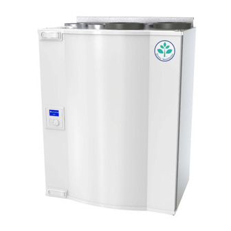
5 Product information 5.1 General The SAVE VTR 200/B is a heat recovery ventilation unit, with a built in rotary heat exchanger. The SAVE VTR 200/B is suitable for smaller flats or houses. It supplies filtered outdoor air to residential areas and extract air from bathroom, kitchen and wet rooms. -
Page 6: Technical Data
5.3 Technical Data 5.3.1 Dimensions and Weight Fig. 1 Dimensions and weight, left hand unit Model SAVE VTR 200/B Including hatch Including bracket Model SAVE VTR 200/B Model Weight (Kg) SAVE VTR 200/B 1180 SAVE VTR 200/B Installation and Service... - Page 7 Outdoor air Cooker hood air Exhaust air Extract air 5.3.3 Power consumption and fuse size SAVE VTR 200/B come with 500 W or 1000 W installed re-heater battery. Table 1: Electrical data 500 W 1000 W Re-heater (W) Fans (W)
-
Page 8: Installation
Systemair products. 6.2 Where/how to install The SAVE VTR 200/B can be installed in any room in the household. 6.3 Installation procedure Prepare the surface where the unit is to be mounted. Make sure that the surface is flat, vertical and that it supports the weight of the unit. -
Page 9: Condensation Drainage
The control panel is used to make the necessary adjustments. An external control panel can be connected on the top of the unit. The illustration below shows the control panel with a short description. SAVE VTR 200/B Installation and Service Systemair Sverige AB... - Page 10 C. Nominal ventilation: Will give required air change under normal conditions. D. Maximum ventilation: To increase the airflow if necessary. E. Auto ventilation: Will regulate after the pre-setting for the demand control settings. SAVE VTR 200/B Installation and Service Systemair Sverige AB 208061...
-
Page 11: Start Up Wizard
• a factory reset is performed • a new print card is installed (spare part) In this case the unit type must be entered ( SAVE VTR 200/B ) The airflow in the Start up wizard can be set by either l/s, m /h or a percentage with the Fan control. - Page 12 Password XXXX Locked YES/NO Use the SELECTION knob for each digit and confirm with the ENTER button after each set digit and choose NO for the system not be locked. SAVE VTR 200/B Installation and Service Systemair Sverige AB 208061...
-
Page 13: System Curves
/h, you need to know the system’s pressure in order to choose a suitable system curve. 7.3.1 Flow settings supply air, F7 type filter Fig. 4 Supply air flow settings, F7 type filter SAVE VTR 200/B Installation and Service Systemair Sverige AB 208061... - Page 14 7.3.2 Flow settings supply air, G3 type filter Fig. 5 Supply air flow settings, G3 type filter 7.3.3 Flow settings exhaust air, G3 type filter Fig. 6 Exhaust air flow settings, G3 type filter SAVE VTR 200/B Installation and Service Systemair Sverige AB 208061...
-
Page 15: Airflow Settings
Choose System curve. SF: 4 EF: 4 6. Press RETURN once the system curves has been set and go to Airflow Airflow l/s or m When settings are done, press ENTER. High SAVE VTR 200/B Installation and Service Systemair Sverige AB 208061... -
Page 16: Moisture Transfer Control
Approximate values of relative humidity in the extract air at cold outdoor temperatures. In newly constructed houses it might be necessary with a higher defrost level during the first winter period. SAVE VTR 200/B Installation and Service Systemair Sverige AB... -
Page 17: Programming The Week Schedule
OFF level. Per 1: 07:00 16:00 Per 2: 00:00 00:00 6. Go back to the previous dialogue frame with the Week program RETURN button and go down to Airflow. Airflow SAVE VTR 200/B Installation and Service Systemair Sverige AB 208061... -
Page 18: Ext/Force Run
(for example lowering the extract air airflow when an open fire place is used). See chapter 9.5. DI 3 is prepared and already connected internally for easy access on the unit. See chapter 7.11. SAVE VTR 200/B Installation and Service Systemair Sverige AB... -
Page 19: Electrical Connections
Fig. 7 Print card position 7.10.1 Print card layout The SAVE VTR 200/B is equipped with built-in regulation and internal wiring. The figure shows the print card. See wiring diagram for more information. SAVE VTR 200/B... - Page 20 Terminals for internal relative humidity sensor 7.10.2 External connections on the print card Connection terminals for external equipment can be found on the main print card inside the electrical connection box. SAVE VTR 200/B Installation and Service Systemair Sverige AB 208061...
-
Page 21: External Connections On Top Of The Unit
2. Connection to control panel 3. External Modbus connection 4. Cable glands 8 Before starting the system When the installation is finished, check that: • The unit is installed in accordance with the instructions SAVE VTR 200/B Installation and Service Systemair Sverige AB 208061... -
Page 22: Operation
The fan can be set to OFF by activating manual fan stop. See the Installation and Service manual, chapter Service menu overview: Manual fan stop. SAVE VTR 200/B Installation and Service Systemair Sverige AB... -
Page 23: Manual And Automatic Summer Mode
Shows selected time interval Filter period between filter change. Time to replace: Set Reset of the filter period 12month to YES after completed filter change. Reset NO/YES Set time between filter changes. SAVE VTR 200/B Installation and Service Systemair Sverige AB 208061... - Page 24 2 periods per Per 1: 07:00 16:00 day. Per 2: 00:00 00:00 Set week day and time interval for the time you want the unit to be in ON mode. SAVE VTR 200/B Installation and Service Systemair Sverige AB 208061...
- Page 25 EF time in the left column for all levels. The right column continues to count ahead and can not be reset. Note: Factory reset (see Functions –>Factory reset) will not affect this function SAVE VTR 200/B Installation and Service Systemair Sverige AB 208061...
- Page 26 On/Off / Variable type. Control Set On/Off to active temperature control and defrosting based on defrost levels 0–5. Set Variable to activate temperature control and moisture transfer control (if available). SAVE VTR 200/B Installation and Service Systemair Sverige AB 208061...
- Page 27 System curve shall only be available in case a system with that type of fan control is used. Fan control Airflow unit Default value: l/s Airflow unit l/s / m /h / % SAVE VTR 200/B Installation and Service Systemair Sverige AB 208061...
- Page 28 ETS: Extract air temp sensor. Unused/OT/FPS 20.0 PHS: Preheater sensor. OS 10.5 FPS: Frost protection sensor. RH 0% OS: Outdoor air temp sensor. OT: Overheat protection sensor. RH: Relative humidity sensor. SAVE VTR 200/B Installation and Service Systemair Sverige AB 208061...
- Page 29 DI3: Fan configuration DI6 ON/OFF DI4: Heater deactivated DI7 ON/OFF DI5: Extended/forced running DI6 for rotating heat exchanger: Rotor sensor DI6 for counter flow heat exchanger: Bypass damper limit switch DI7: Home/leave SAVE VTR 200/B Installation and Service Systemair Sverige AB 208061...
- Page 30 0. Counting down for the predefined period starts when DI function is deactivated. Default value is 0 sec. Actual delay counter is shown and counting when function is activated. SAVE VTR 200/B Installation and Service Systemair Sverige AB 208061...
- Page 31 It is recommended to connect DI7 and DI1 or DI3 in parallel. If DI7 is activated, set the fans speed to min. Airflow settings are done when configuring DI1/DI3. SAVE VTR 200/B Installation and Service Systemair Sverige AB 208061...
- Page 32 0 ppm — for the bounded sensors. RH: 0% — Highest actual sensor signal presented via –/modbus/wireless. Unbound sensor presented as – (none). Modbus sensors has priority over wireless sensors. SAVE VTR 200/B Installation and Service Systemair Sverige AB 208061...
- Page 33 Data: The actual value from module/Comm fail: Communication failure, se manual for actual module for troubleshooting. To reset all bound nodes, see user manual for Gateway Wireless. SAVE VTR 200/B Installation and Service Systemair Sverige AB 208061...
- Page 34 Modbus Settings user manual for residential units in the online catalogue Address 1 Baud 19200 Parity None www.systemair.com. Modbus Shows current status of communication. Gateway Gateway State Not present/... SAVE VTR 200/B Installation and Service Systemair Sverige AB 208061...
- Page 35 Shows current version of the unit and Z-wave Gateway. Update Service Alarms Shows the alarms that have Alarms been triggered. See alarm list (chapter 10.5) Frost Bypass Pb Fail Temp Filter Low SS Defrost SAVE VTR 200/B Installation and Service Systemair Sverige AB 208061...
-
Page 36: Service
• This product must only be operated by a person which has suitable knowledge or education within this field or carried out with the supervision of a suitably qualified person. 10.2 Internal components Fig. 10 Internal components SAVE VTR 200/B Installation and Service Systemair Sverige AB 208061... -
Page 37: Component Descriptions
For G3 type filter: 11–20, for F7 type filter: 1–10. See chapter 7.3 System curves. 10.3.3 Heat exchanger SAVE VTR 200/B is equipped with a highly efficient, rotating heat exchanger. Required supply air temperature is therefore normally maintained without adding additional heat. -
Page 38: Temperature Sensors
If the supply air temperature is low, it can indicate that the over heat protection is triggered. The overheat protection can be reset by pressing the reset button (1). Fig. 11 Overheat protection reset button SAVE VTR 200/B Installation and Service Systemair Sverige AB... -
Page 39: Trouble Shooting
4. Check if one of the digital inputs 1–3 (DI 1–3) is active and set to off. This would force one or both fans to stop depending on the setup (chapter 9.5). SAVE VTR 200/B Installation and Service Systemair Sverige AB... - Page 40 Noise/vibrations 1. Clean fan impellers. 2. Check that the screws holding the fans are tightened. 3. Check that the anti vibration pads are fitted at the bottom of the unit. SAVE VTR 200/B Installation and Service Systemair Sverige AB 208061...
-
Page 41: Alarm List
Contact your installation company or place of purchase. Filter Time for filter change. The alarm is displayed in the control panel. Change filter according to the instructions in the User Manual. SAVE VTR 200/B Installation and Service Systemair Sverige AB 208061... -
Page 42: Replacing Rotor Drive Belt
Make sure that small children are not beneath the unit when the heat exchanger is removed! Fig. 12 Rotor drive belt 10.6.1 Heat exchanger mounted 1. Stop the unit by disconnecting the mains. SAVE VTR 200/B Installation and Service Systemair Sverige AB 208061... - Page 43 9. Mount the heat exchanger. Don’t forget to reconnect the rotor power and sensor cables. 10.Close the front hatch and connect the unit to mains. 11.Check that the alarm has ceased on the Control Display. Note: If the alarm remains, check the rotor sensor. SAVE VTR 200/B Installation and Service Systemair Sverige AB 208061...
- Page 44 Systemair Sverige AB reserves the right to make changes and improvements to the contents of this manual without prior notice. Systemair UAB Linų st. 101 LT–20174 Ukmergė, LITHUANIA Phone +370 340 60165 Fax +370 340 60166 www.systemair.com...
Need help?
Do you have a question about the SAVE VTR 200/B and is the answer not in the manual?
Questions and answers