Table of Contents
Advertisement
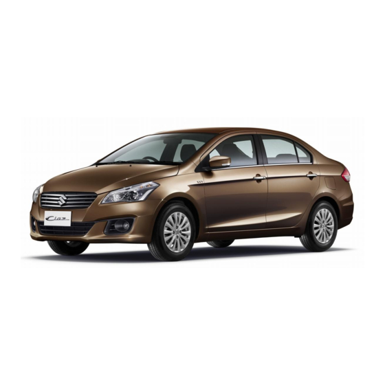
This owner's manual applies to the Ciaz series.
79MH0002
NOTE: The illustrated model is one of the Ciaz series.
© 2015
All rights reserved.
No part of this document may be reproduced or transmitted in any form or by any means, electronic or
mechanical, for any purpose, without the express written permission of Suzuki Motor Corporation.
79MS0-14E
Advertisement
Table of Contents

Subscribe to Our Youtube Channel
Related Manuals for Suzuki Ciaz series


Summary of Contents for Suzuki Ciaz series
- Page 1 NOTE: The illustrated model is one of the Ciaz series. © 2015 All rights reserved. No part of this document may be reproduced or transmitted in any form or by any means, electronic or mechanical, for any purpose, without the express written permission of Suzuki Motor Corporation. 79MS0-14E...
- Page 2 Please read this manual carefully cial information, the symbol and the tion in this manual and your vehicle. before operating your new SUZUKI and words WARNING, CAUTION, NOTICE SUZUKI MOTOR CORPORATION review the manual from time to time. It and NOTE have special meanings.
- Page 3 CB (Citizen’s Band) radios may cause electronic interfer- ence with your vehicle’s ignition sys- tem, resulting in vehicle performance problems. Consult your SUZUKI dealer or qualified service technician for advice on installing such mobile communication equipment. 79MS0-14E...
- Page 4 INTRODUCTION Thank you for choosing SUZUKI and welcome to our growing family. Your choice was a wise one; SUZUKI products are a great value that will give you years of driving pleasure. This Owner’s Manual was prepared to help you have a safe, enjoyable, and trouble-free experience with your SUZUKI. In it you will learn about the vehicle’s operation, its safety features and maintenance requirements.
- Page 5 A wide variety of non-genuine replacement parts and accessories for SUZUKI vehicles are currently available in the market. Using these parts and accessories can affect the vehicle performance and shorten its useful life. Therefore, installation of non-genuine SUZUKI parts and accessories is not covered under warranty.
- Page 6 SERVICE STATION GUIDE 1. Fuel (see section 1) 2. Engine hood (see section 5) 3. Tire changing tools (see section 8) 4. Engine oil dipstick <Yellow> (see section 7) 5. CVT fluid dipstick <Orange> (see section 7) 6. Engine coolant (see section 7) 7.
- Page 7 MEMO 79MS0-14E...
- Page 8 TABLE OF CONTENTS FUEL RECOMMENDATION BEFORE DRIVING OPERATING YOUR VEHICLE DRIVING TIPS OTHER CONTROLS AND EQUIPMENT VEHICLE LOADING AND TOWING INSPECTION AND MAINTENANCE EMERGENCY SERVICE APPEARANCE CARE GENERAL INFORMATION SPECIFICATIONS INDEX 79MS0-14E...
- Page 9 ILLUSTRATED TABLE OF CONTENTS EXTERIOR, FRONT EXAMPLE 1. Engine Hood (P.5-2) 2. Windshield Wiper (P.2-65) 3. Frame Hook (P.5-14) 4. Front Fog Light (if equipped) (P.2-63, 7-32) 5. Headlight (P.2-62, 7-30) 6. Outside Rearview Mirror (P.2-21) 7. Door Locks (P.2-2) 8.
- Page 10 ILLUSTRATED TABLE OF CONTENTS EXTERIOR, REAR EXAMPLE 1. Radio Antenna (P.5-28) 2. License Plate Light (P.7-34) 3. Reversing Light (P.7-33) 4. High-mount Stop Light 5. Rear Combination Light (P.7-33) 6. Trunk Lid (P.2-4) * If your vehicle is equipped with rear spoiler, High-mount Stop Light is built into rear spoiler.
- Page 11 ILLUSTRATED TABLE OF CONTENTS INTERIOR, FRONT EXAMPLE 1. Front Passenger’s Front Air Bag (P.2-37) 2. Electric Window Controls (P.2-17)/ Electric Mirrors Control Switch (P.2-21)/ Outside Rearview Mirrors Folding Switch (if equipped) (P.2-21) 3. Glove Box (P.5-9) 4. Parking Brake Lever (P.3-10) 5.
- Page 12 ILLUSTRATED TABLE OF CONTENTS 1. Sun Visor (P.5-4) VIEW A EXAMPLE 2. Front Interior Light (P.5-5, 7-35) 3. Inside Rearview Mirror (P.2-20) 4. Hands-free Microphone (if equipped) (P.5-52) 79MS0T003 79MS0-14E...
- Page 13 ILLUSTRATED TABLE OF CONTENTS 1. Remote Audio Controls (if equipped) VIEW B EXAMPLE (P.5-63) 2. Driver’s Front Air Bag (P.2-37) 3. Lighting Control Lever (P.2-62)/ Turn Signal Control Lever (P.2-63) 4. Tilt Steering Lock Lever (P.2-66) 5. Fuel Lid Opener Lever (P.5-1) 6.
- Page 14 ILLUSTRATED TABLE OF CONTENTS 1. Hazard Warning Switch (P.2-64) VIEW C EXAMPLE 2. Audio (if equipped) (P.5-29, 5-71) 3. Instrument Cluster (P.2-43)/ Information Display (P.2-46) 4. Windshield Wiper and Washer Lever (P.2-65) 5. Heating (if equipped) and Air Conditioning System (P.5-15)/ Heated Rear Window Switch (P.2-67) 6.
- Page 15 ILLUSTRATED TABLE OF CONTENTS INTERIOR, REAR EXAMPLE 1. Seat Belts (P.2-25) 2. Assist Grip (if equipped) (P.5-8) 3. Center Interior Light (P.5-5, 7-35) 4. Rear Seats (P.2-24) 5. Rear Armrest with Cup Holders (P.5-12) 79MS0T004 79MS0-14E...
- Page 16 ILLUSTRATED TABLE OF CONTENTS LUGGAGE EXAMPLE COMPARTMENT 1. Luggage Compartment Carpet 2. Luggage Compartment Light (if equipped) (P.5-5) 3. Flat Tire Repair Kit (P.8-5) 4. Jack (P.8-1) 5. Wheel Brace (P.8-1) 6. Jack Handle (P.8-1) 79MS0T005 79MS0-14E...
- Page 17 ILLUSTRATED TABLE OF CONTENTS MEMO 79MS0-14E...
-
Page 18: Fuel Recommendation
FUEL RECOMMENDATION FUEL RECOMMENDATION Fuel Recommendation ............1-1 65D394 79MS0-14E... - Page 19 FUEL RECOMMENDATION PLOMO” or “KHUSUS BENSIN TANPA Fuel Recommendation NOTICE TIMBAL”. If the “RON 95” label is attached, you must Be careful not to spill fuel containing use unleaded gasoline with an octane alcohol while refueling. If fuel is number (RON) of 95 or higher. spilled on the vehicle body, wipe it up immediately.
-
Page 20: Before Driving
BEFORE DRIVING BEFORE DRIVING Keys ..................2-1 Door Locks ................2-2 Keyless Push Start System Remote Controller/ Keyless Entry System Transmitter ........2-6 Theft Deterrent Alarm System ........... 2-14 Windows ................2-17 Mirrors .................. 2-20 Front Seats ................2-22 Rear Seats ................2-24 Seat Belts and Child Restraint Systems ...... -
Page 21: Operating Your Vehicle
Ask troller which has an electronic identification your SUZUKI dealer to have the system code programmed into it. The key or inspected. remote controller communicates the identi-... -
Page 22: Door Locks
• If you own other vehicles with immobi- lizer keys, keep those keys away from the ignition switch or the engine switch when using your SUZUKI, or the engine may not be started because they may interfere with your SUZUKI’s immobilizer system. - Page 23 BEFORE DRIVING To unlock a driver’s door from outside the NOTE: Central Door Locking System vehicle, insert the key and turn the top of You can switch the function that unlocks all the key toward the rear of the vehicle. doors from twice operations to once opera- tion, and vice versa, via the setting mode EXAMPLE...
- Page 24 BEFORE DRIVING NOTE: Child-Proof Locks (rear door) Trunk Lid • You can also lock or unlock all doors by operating the transmitter or remote con- troller. Refer to “Keyless Push Start Sys- EXAMPLE tem Remote Controller/Keyless Entry System Transmitter” in this section. •...
- Page 25 If the trunk lid cannot be unlatched by WARNING pushing the unlatch switch (1), have the vehicle inspected by your SUZUKI dealer. Always make sure that the trunk lid is closed and latched securely. Other- wise, it may open unexpectedly while driving.
- Page 26 Your vehicle is equipped with either a key- SUZUKI dealer. less push start system remote controller (Type A) or a keyless entry system trans- mitter (Type B). The remote controller has a keyless entry system and a keyless push start system.
- Page 27 BEFORE DRIVING Central door locking system Be sure the doors are locked after you • To lock all doors, push the “LOCK” but- operate the “LOCK” button (1). ton (1) once. If no door is opened within about 30 sec- •...
- Page 28 “Information Display” in this section. • If you lose one of the remote controllers, EXAMPLE ask your SUZUKI dealer as soon as pos- When the doors are unlocked: sible for a replacement. Be sure to have • The turn signal lights will flash twice and...
- Page 29 BEFORE DRIVING NOTE: NOTE: NOTICE • The door locks cannot be operated by • If the remote controller is outside the the request switch under the following request switch operating range The remote controller is a sensitive conditions: described above, you will not be able to electronic instrument.
- Page 30 • If you lose one of the remote controllers, With the ignition mode changed to “LOCK” ask your SUZUKI dealer as soon as pos- (OFF) by pressing the engine switch, bring sible for a replacement. Be sure to have...
- Page 31 BEFORE DRIVING The indicator light will turn off within sev- Replacement of the battery eral seconds after the remote controller is If the remote controller becomes unreli- returned to an area of the vehicle other able, replace the battery. than the trunk. To replace the battery of the remote con- If the remote controller is left in the vehicle troller:...
- Page 32 BEFORE DRIVING Central door locking system Keyless Entry System Transmitter WARNING • To lock all doors, push the “LOCK” but- (Type B) ton (1) once. Swallowing a lithium battery may • To unlock only the driver’s door, push the cause serious internal injury. Do not “UNLOCK”...
- Page 33 • If you lose one of the transmitters, ask your SUZUKI dealer as soon as possible 68LM249 for a replacement. Be sure to have your (3) Lithium disc type battery:...
-
Page 34: Theft Deterrent Alarm System
BEFORE DRIVING NOTE: Theft Deterrent Alarm System WARNING • The theft deterrent alarm system gener- ates alarms when any of the predeter- Swallowing a lithium battery may The theft deterrent alarm system is armed mined conditions is met. However, the cause serious internal injury. - Page 35 BEFORE DRIVING How to arm the theft deterrent alarm NOTE: How to stop the alarm system (when enabled) • To prevent the alarm from being acci- Should the alarm be triggered accidentally, Lock all doors (including the trunk lid) dentally triggered, avoid arming it while unlock the doors using the keyless push using the keyless push start system anyone remains inside the vehicle.
- Page 36 BEFORE DRIVING Checking whether the alarm has been How to switch the state of the theft EXAMPLE triggered during parking deterrent alarm system If the alarm was triggered due to an unau- You can switch the theft deterrent alarm thorized entry into the vehicle and you then system from the enabled state to the dis- press the engine switch to change the igni- abled state, and vice versa, using the fol-...
- Page 37 BEFORE DRIVING 1) With the ignition mode “ON” or the igni- Every time you perform the series of the Windows tion switch in the “ON” position, close above steps, the state of the theft deterrent all the doors and turn the lock knob (1) alarm system changes from the currently on the driver’s door in the unlocking selected one to the other.
- Page 38 BEFORE DRIVING Passenger’s door Lock switch EXAMPLE EXAMPLE CLOSE OPEN 81A009 79MH0214 79MH0215 To open a window, push the top part of the The passenger’s door has a switch (5) to The driver’s door also has a lock switch for switch and to close the window lift up the operate the passenger’s window.
- Page 39 BEFORE DRIVING Pinching Prevention Function WARNING CAUTION The driver’s window is equipped with the • You should always lock the pas- • The pinching prevention function pinching prevention function. The function senger’s window operation when does not act while you are holding detects a foreign object caught in the win- there are children in the vehicle.
- Page 40 To adjust the mirror, set function. Have your vehicle inspected by the selector tab (1) to the day position, an authorized SUZUKI dealer. then move the mirror up, down or sideways by hand to obtain the best view.
- Page 41 BEFORE DRIVING 1) Move the selector switch to the left or Outside Rearview Mirrors Outside Rearview Mirrors Folding right to select the mirror you wish to Switch (if equipped) adjust. Adjust the outside rearview mirrors so you 2) Press the outer part of the switch that can just see the side of your vehicle in the corresponds to the direction in which mirrors.
-
Page 42: Front Seats
BEFORE DRIVING Front Seats WARNING All seatbacks should always be in an upright position when driving, or seat Seat Adjustment belt effectiveness may be reduced. Seat belts are designed to offer maxi- WARNING mum protection when seatbacks are in the upright position. Never attempt to adjust the driver’s seat or seatback while driving. - Page 43 BEFORE DRIVING Seat position adjustment lever (1) Pull the lever up and slide the seat. EXAMPLE Seatback angle adjustment lever (2) Pull the lever up and move the seatback. Seat height adjustment lever (3) (if equipped) Pull the lever up to raise the seat. Push the lever down to lower the seat.
- Page 44 BEFORE DRIVING NOTE: Head Restraints Rear Seats It may be necessary to recline the seat- back to provide enough overhead clear- ance to remove the head restraint. Head Restraints Front Head restraints are designed to help reduce the risk of neck injuries in the case EXAMPLE of an accident.
- Page 45 BEFORE DRIVING Seat Belts and Child Restraint Systems Above the pelvis Across the pelvis 65D606 65D201 WARNING WARNING • Never allow persons to ride in the (Continued) 65D231S cargo area of a vehicle. In the event • Seat belts should never be worn of an accident, there is a much with the straps twisted and should WARNING...
- Page 46 BEFORE DRIVING WARNING WARNING (Continued) (Continued) • Never use the same seat belt on • For children, if the shoulder belt more than one occupant and never irritates the neck or face, move the attach a seat belt over an infant or child closer to the center of the as low as possible child being held on an occupant’s...
- Page 47 BEFORE DRIVING All Seat Belts Except Rear Center Lap-Shoulder Belt All seat belts except rear center are the lap-shoulder belt. Emergency locking retractor (ELR) Low on hips The seat belt has an emergency locking retractor (ELR), which is designed to lock the seat belt only during a sudden stop or impact.
- Page 48 BEFORE DRIVING Lap Belt EXAMPLE Rear Center Seat Belt To fasten the belt, pull the latch plate attached to the seat belt across your hips and press it straight into the buckle until you hear a “click”. To reduce the risk of sliding under the belt during a collision, position the belt across your lap as low on your hips as possible and adjust it to a...
- Page 49 BEFORE DRIVING To unfasten the belt, press the release but- Driver’s Seat Belt Reminder ton on the buckle catch. TO LOOSEN EXAMPLE EXAMPLE Right angle 80JS029 To lengthen, release the latch plate from 79MH0239 the buckle, pull the latch plate (adjuster) in 79MS0T205 the direction of the arrow, at right angles to NOTE:...
- Page 50 BEFORE DRIVING When the driver doesn’t buckle his or her Shoulder Anchor Height Adjuster Seat Belt Inspection seat belt with the ignition switch in the “ON” position or the ignition mode is “ON”, the driver’s seat belt reminder light in the EXAMPLE EXAMPLE instrument cluster will blink until the...
- Page 51 Booster seat 60G332S EXAMPLE Infant restraint - rear seat only EXAMPLE 80JC008 SUZUKI highly recommends that you use 80JC007 a child restraint system to restrain infants and small children. Many different types of child restraint systems are available; make 2-31...
- Page 52 (lap belts or the lap portion of lap-shoulder far enough forward so that the child’s belts). Whenever possible, SUZUKI rec- feet do not touch the front seatback. ommends that child restraint systems be This will help avoid injury to the child installed on the rear seat.
- Page 53 BEFORE DRIVING Installation with Lap-Shoulder Seat WARNING Belts Children could be endangered in a crash if their child restraint systems ELR type belt are not properly secured in the vehi- cle. When installing a child restraint EXAMPLE system, be sure to follow the instruc- tions below.
- Page 54 This section of the owner’s manual For precautions and general information To lengthen or tighten the belt, refer to the describes your SUZUKI’s SEAT BELT including servicing the pretensioner sys- “Lap-belt” item in this “Seat Belts and PRETENSIONER SYSTEM.
- Page 55 Have both systems inspected by an authorized SUZUKI dealer as soon as Sit fully back in the seat; sit up straight; do possible. not lean forward or sideways. Adjust the...
- Page 56 System (air bags) WARNING This section of the owner’s manual describes the protection provided by your SUZUKI’s SUPPLEMENTAL RESTRAINT SYSTEM (air bags). Please read and follow ALL these instructions carefully to minimize your risk of severe injury or death in the event of a collision.
- Page 57 (or the seat belt pretensioner seat belts are needed to restrain occu- system) may not work properly. Have the pants from further movements during the air bag system inspected by an authorized accident. SUZUKI dealer as soon as possible. 2-37 79MS0-14E...
- Page 58 BEFORE DRIVING Therefore, an air bag is NOT a substitute Front passenger’s front air bag for seat belts. To maximize your protection, EXAMPLE ALWAYS WEAR YOUR SEAT BELTS. Be aware that no system can prevent all pos- sible injuries that may occur in an accident. Driver’s front air bag EXAMPLE 58MS030...
- Page 59 BEFORE DRIVING Conditions of front air bags deployment Conditions of front air bags may inflate (inflation) Receiving a strong impact to the lower body of your vehicle, the front air bags will inflate in many cases. 80J101 • Landing hard or falling 80J097 •...
- Page 60 BEFORE DRIVING Front air bags may not inflate The front air bags may not inflate when the impact is absorbed since the collision object moved, vehicle body deformed, or collision angle was greater than about 30 degrees from the front. 80J119 80J104 •...
- Page 61 BEFORE DRIVING A seat belt helps keep you in the proper How the system works position for maximum protection when an air bag inflates. Adjust your seat as far In a frontal collision, the crash sensors will back as possible while still maintaining detect rapid deceleration, and if the con- control of the vehicle.
- Page 62 These objects may interfere with air your air bags. Please remind anyone who bag operation or may be propelled services your SUZUKI that it has air bags. by the air bag in the event of a crash. Either of these conditions Service on or around air bag components may cause severe injury.
- Page 63 BEFORE DRIVING Instrument Cluster 1. Speedometer 2. Tachometer 3. Fuel gauge 4. Temperature gauge 5. Information display 6. Trip meter selector knob 7. Indicator selector knob 8. Warning and indicator lights EXAMPLE 79MS0T206 2-43 79MS0-14E...
- Page 64 BEFORE DRIVING Refer to “Low Fuel Warning Light” in Speedometer Fuel Gauge “Warning and Indicator Lights” in this sec- tion for details. The speedometer indicates vehicle speed. The mark (2) indicates that the fuel filler door is located on the left side of the vehi- cle.
-
Page 65: Temperature Gauge
BEFORE DRIVING To reduce the brightness of the instrument Temperature Gauge Brightness Control panel lights, turn the brightness control knob (1) counterclockwise. WARNING EXAMPLE If you attempt to adjust the display while driving, you could lose control of the vehicle. Do not attempt to adjust the display while driving. -
Page 66: Information Display
BEFORE DRIVING The information display shows the follow- Information Display EXAMPLE ing information. Display (A) The information display is shown when the Thermometer ignition switch is in the “ON” position or the ignition mode is “ON”. Display (B) (for CVT vehicles) Transaxle selector position indicator Display (C) Trip meter / Instantaneous fuel consump-... - Page 67 BEFORE DRIVING When the display (C) shows the driving Thermometer Transaxle selector position indica- range, you can change the unit of tem- tor (for CVT vehicles) perature. When the ignition switch is in the “ON” To change the unit of temperature, while position or the ignition mode is “ON”, the pushing and holding the trip meter selector display (A) shows the thermometer.
- Page 68 BEFORE DRIVING Trip meter / Instantaneous fuel con- Push the trip meter selector EXAMPLE sumption / Average fuel consump- knob (2). tion / Driving range Push the indicator selector When the ignition switch is in the “ON” knob (3). position or the ignition mode is “ON”, the display (C) shows one of the following five (c) Trip meter A indications, trip meter A, trip meter B,...
- Page 69 BEFORE DRIVING Trip meter Instantaneous Fuel Consumption NOTE: The trip meter can be used to measure the If you selected instantaneous fuel con- • The display does not show the value distance traveled on short trips or between sumption the last time you drove the vehi- unless the vehicle is moving.
- Page 70 BEFORE DRIVING Average fuel consumption NOTE: If you selected average fuel consumption When you reset the indication or reconnect EXAMPLE the last time you drove the vehicle, the dis- the negative (–) terminal to the battery, the play shows the last value of average fuel value of average fuel consumption will be consumption from previous driving when shown after driving for a while.
- Page 71 BEFORE DRIVING Driving range NOTE: Odometer If you selected driving range the last time • If you refuel when the ignition switch is in you drove the vehicle, the display indicates the “ON” position or the ignition mode is When the ignition switch is in the “ON” “---”...
- Page 72 BEFORE DRIVING Clock When the ignition switch is in the “ON” position or the ignition mode is “ON”, the display (E) shows the time. To change the time indication: 1) Push the trip meter selector knob (2) and the indicator selector knob (3) together.
- Page 73 BEFORE DRIVING Setting Mode In the setting mode, you can set up the following functions. Indication Functions Central door locking system “ ” Door locking and unlocking buzzer “ ” Additional flashes of the turn signal “ ” Security system “ ”...
- Page 74 BEFORE DRIVING Central door locking system “ ” Additional flashes Turn the indicator selector knob • : Unlock all doors by turning the of the turn signal “ ” (3). key, pushing the keyless entry • : Turn signal flashes three system transmitter, keyless times after the turn signal...
-
Page 75: Warning And Indicator Lights
BEFORE DRIVING The light should go out after starting the Warning and Indicator Lights engine and fully releasing the parking EXAMPLE brake, if the fluid level in the brake fluid reservoir is adequate. Brake System Warning Light The light also comes on together with the ABS warning light when the rear brake force control function (proportioning valve 84MS0T223... - Page 76 If any of the following conditions equipped with the rear brake force control occur, you should immediately ask function (proportioning valve function) and your SUZUKI dealer to inspect the there may be something wrong with both brake system. the rear brake force control function and •...
- Page 77 Check the oil level and add oil if necessary. inspected immediately by your SUZUKI If there is enough oil, the lubrication sys- dealer. tem should be inspected by your SUZUKI dealer before you drive the vehicle again. NOTICE • If you operate the engine with this light on, severe engine damage can result.
- Page 78 “ON” so you can check the light is working. or the engine switch is pressed to Bring the vehicle to your SUZUKI dealer to If this light comes on when the engine is change the ignition mode to “ON”, have the damage fixed.
- Page 79 BEFORE DRIVING Immobilizer/Keyless Push Start Open Door Warning Light Low Fuel Warning Light System Warning Light 54G391 54G343 80JM122 This light remains on until all doors are If this light comes on, fill the fuel tank completely closed. immediately. When the ignition switch is turned to the “ON”...
- Page 80 If this light comes on while driving, the signal lights. power steering system may not work prop- erly. Have the system inspected by your SUZUKI dealer. Main Beam (high beam) Indicator Light NOTE: Following operations of the steering wheel...
- Page 81 BEFORE DRIVING Keyless Push Start System Remote “PUSH” Indicator Light “ACC” Indicator Light (if equipped) Controller Battery Consumption (if equipped) Warning Light (if equipped) 82K097 82K174 This light comes on when the ignition mode is “ACC”. 70K122 If this light comes on when depressing the brake pedal, you can start the engine.
-
Page 82: Lighting Control Lever
BEFORE DRIVING Lighting Operation Lighting Control Lever EXAMPLE EXAMPLE 60MK012 With the headlights on, push the lever for- ward to switch to the high beams (main 60MK011 65D611 beams) or pull the lever toward you to To turn the lights on or off, twist the knob switch to the low beams. -
Page 83: Front Fog Light Switch
BEFORE DRIVING Turn Signal Operation Front Fog Light Switch Turn Signal Control Lever (if equipped) With the ignition switch in the “ON” position or the ignition mode “ON”, move the lever up or down to activate the right or left turn signals. -
Page 84: Hazard Warning Switch
Hazard Warning Switch You can customize the setting for the num- ber of times of flashing of the turn signal and its indicator. Please ask an authorized SUZUKI dealer for the customization. EXAMPLE 60MK014 EXAMPLE Sometimes, such as when changing lanes,... -
Page 85: Windshield Wiper And Washer
BEFORE DRIVING Windshield Wipers Windshield Washer Windshield Wiper and Washer Lever EXAMPLE EXAMPLE 79MHA0001 79MH0235 To turn the windshield wipers on, move the To spray windshield washer fluid, pull the lever down to one of the three operating lever toward you. The windshield wipers 57L21128 positions. - Page 86 BEFORE DRIVING Tilt Steering Lock Lever NOTICE WARNING To help prevent damage to the wind- Never attempt to adjust the steering shield wiper and washer system wheel height while the vehicle is EXAMPLE components, you should take the fol- moving or you could lose control of lowing precautions: the vehicle.
- Page 87 BEFORE DRIVING When the rear window is misted, push this Horn Heated Rear Window Switch switch (1) to clear the window. An indicator light will be lit when the defog- Type1 ger is on. The defogger will work only EXAMPLE when the engine is running.
- Page 88 OPERATING YOUR VEHICLE OPERATING YOUR VEHICLE Exhaust Gas Warning ............3-1 Daily Inspection Checklist ..........3-1 Engine Oil Consumption ............ 3-2 Ignition Switch (Vehicle without Keyless Push Start System) ....3-3 Engine Switch (Vehicle with Keyless Push Start System) ......3-5 Keyless Push Start System (if equipped) ......
-
Page 89: Inspection And Maintenance
OPERATING YOUR VEHICLE Exhaust Gas Warning Daily Inspection Checklist WARNING (Continued) • Do not park with the engine run- Before Driving ning for a long period of time, even in an open area. If it is necessary to sit for a short time in a parked vehi- cle with the engine running, make sure the air intake selector is set to “FRESH AIR”... -
Page 90: Engine Oil Consumption
OPERATING YOUR VEHICLE NOTE: vehicle. Make sure that you cannot Engine Oil Consumption It is normal for water to drip from the air open the hood all the way without conditioning system after use. releasing the secondary latch. Be sure It is normal for the engine to consume to close the hood securely after check- 4) Make sure the hood is fully closed and... - Page 91 OPERATING YOUR VEHICLE making it appear that the oil level has not Ignition Switch changed. EXAMPLE You should also be aware that the diluting (Vehicle without Keyless ingredients evaporate out when the vehicle Push Start System) is subsequently driven at high speeds, such as on an expressway, making it appear that oil is excessively consumed after high-speed driving.
- Page 92 OPERATING YOUR VEHICLE Manual transaxle Accessories such as the radio can oper- Turn to “LOCK” ate, but the engine is off. This is the normal operating position. All electrical systems are on. Push START This is the position for starting the engine using the starter motor.
- Page 93 “N”.) SUZUKI dealer. • Do not leave the ignition switch in the “ON” position if the engine is Press the engine switch to select this igni- not running as the battery will dis- tion mode to use such electric equipment charge.
-
Page 94: Keyless Push Start System
OPERATING YOUR VEHICLE NOTE: Engine Switch Illumination Keyless Push Start System You do not need to keep the engine switch pressed to start the engine. (if equipped) The engine switch is illuminated (lit) in the following situations: NOTICE • When the engine is off and the driver’s Provided the keyless push start system door is open, or for 15 seconds after the remote controller is within the “interior... - Page 95 OPERATING YOUR VEHICLE Every time you press the engine switch, Selection of Ignition Modes the ignition mode changes as follows. Press the engine switch to select the “ACC” or “ON” mode as follows when you use an electric accessory or check the operation of instruments without running Gearshift the engine.
- Page 96 “P” position the keyless push start system. Contact the ignition mode cannot be returned to an authorized SUZUKI dealer for an “LOCK” (OFF). inspection of the system. • The immobilizer/keyless push start sys- If the “PUSH”...
- Page 97 OPERATING YOUR VEHICLE • Always keep the remote controller with “Remote Controller Outside” Warn- you as the driver. When the conditions described below are Interior Workable Area for Engine met, the system gives a “remote controller Starting, Ignition Mode Selection outside”...
-
Page 98: Parking Brake Lever
The parking brake lever is located between –The remote controller is outside the rized SUZUKI dealer. the seats. To set the parking brake, hold vehicle but very close to a door. the brake pedal down and pull the parking –The remote controller is on the instru-... - Page 99 OPERATING YOUR VEHICLE Parking Brake Reminder Buzzer Pedal WARNING A buzzer sounds intermittently to remind Always set the parking brake fully you to release the parking brake if you Manual transaxle before leaving your vehicle or it may start the vehicle without releasing the park- move, causing injury or damage.
- Page 100 Depressing the accelerator pedal braking. increases power output and speed. Brake Pedal (2) Your SUZUKI vehicle is equipped with front and rear disc brakes. Depressing the brake pedal applies both sets of brakes. You may hear occasional brake squeal 79MS0T302 when you apply the brakes.
- Page 101 OPERATING YOUR VEHICLE NOTE: Starting a Cold and Warm Engine Starting the Engine CVT vehicles have a starter interlock device which is designed to keep the (Vehicle with Keyless Push With your foot off the accelerator pedal, starter from operating if the transaxle is in crank the engine by turning the ignition key Start System) any of the drive positions.
- Page 102 OPERATING YOUR VEHICLE Stopping the engine NOTICE • Depress the engine switch to stop the • Do not depress the accelerator engine after the vehicle stopped com- during the engine starting proce- pletely. dure. • In case of emergency, you can stop the •...
- Page 103 (2) for about 2 seconds. the accelerator pedal all the way to the floor while cranking. This should clear the engine if it is flooded. If you are unable to start the engine using this procedure, consult your SUZUKI dealer. 3-15 79MS0-14E...
- Page 104 “LOCK” (OFF) using the engine switch by an authorized SUZUKI dealer after troller battery consumption warning light and then lock the doors. Without returning doing the following: in the instrument cluster will come on for the ignition mode to “LOCK”...
-
Page 105: Using The Transaxle
OPERATING YOUR VEHICLE Starting off Downshifting maximum allowable Using the Transaxle To start off, depress the clutch pedal all the speeds way to the floor and shift into 1st gear. After releasing the parking brake, gradually Downshifting km/h (mph) Manual Transaxle release the clutch. - Page 106 OPERATING YOUR VEHICLE S (sport) mode switch Continuously Variable Transaxle WARNING The sport mode switch (1) is used to turn (CVT) on and off the sport mode. • Reduce your speed and downshift To turn on the sport mode, push in the to a lower gear before going down switch and sport mode indicator (2) will a long or steep hill.
- Page 107 OPERATING YOUR VEHICLE Gearshift lever P (Park) Shift with the knob button (1) Use this position to lock the transaxle pushed in and the brake pedal when the vehicle is parked or when start- depressed. ing the engine. Shift into Park only when the vehicle is completely stationary.
- Page 108 OPERATING YOUR VEHICLE L (Low) 4) With the release button (1) pushed, If You Cannot Shift CVT Gearshift Use this position to provide maximum push the knob button (2) and shift the Lever Out of “P” (PARK) power when climbing steep hills or driving gearshift lever to the desired position.
- Page 109 OPERATING YOUR VEHICLE Braking WARNING WARNING If water gets into the brake devices, Even without reserve power in the brake performance may become poor brake system, you can still stop the unpredictable. After driving vehicle by pressing the brake pedal through water or washing the under- harder than normally required.
- Page 110 ABS system. The ABS will not work if vehicle speed is control. However, remember that Ask your SUZUKI dealer to inspect under about 9 km/h (6 mph). ABS will not compensate for bad the ABS system immediately. If the...
- Page 111 OPERATING YOUR VEHICLE How the ABS Works A computer continuously monitors wheel speed. computer compares changes in wheel speed when braking. If the wheels slow suddenly, indicating a skidding situation, computer will change braking pressure several times each second to prevent the wheels from locking.
- Page 112 DRIVING TIPS DRIVING TIPS Running-in ................4-1 Catalytic Converter ............. 4-1 Improving Fuel Economy ........... 4-2 Highway Driving ..............4-3 Driving on Hills ..............4-3 Driving on Slippery Roads ..........4-4 60G409 79MS0-14E...
-
Page 113: Catalytic Converter
DRIVING TIPS Running-in Catalytic Converter NOTICE The future performance and reliabil- ity of the engine depends on the care 52D078S and restraint exercised during its early life. It is especially important to observe the following precautions WARNING during the initial 960 km (600 miles) •... -
Page 114: Improving Fuel Economy
DRIVING TIPS to the catalyst and other vehicle compo- Improving Fuel Economy nents. NOTICE The following instructions will help you improve fuel economy. To minimize the possibility of catalyst Avoid excessive idling or other vehicle damage: If you are to wait for more than a minute •... -
Page 115: Highway Driving
DRIVING TIPS Keep the air cleaner clean Highway Driving Driving on Hills EXAMPLE When driving at highway speeds, pay attention to the following: • Stopping distance progressively increases with vehicle speed. Apply the brakes far enough ahead of the stopping point to allow for the extra stopping dis- tance. -
Page 116: Driving On Slippery Roads
DRIVING TIPS power range. Shift rapidly to prevent the Tire Chains Driving on Slippery Roads vehicle from losing momentum. • When driving down a hill, the engine Tire chains should only be used if they are should be used for braking by shifting to needed to increase traction or are required next lower gear. - Page 117 In addition to following the driving minutes of rocking, we recommend you tips in this section, it is important to to consult your SUZUKI dealer or a observe the following precautions. roadside assistance service. If a towing • Make sure your tires are in good...
- Page 118 DRIVING TIPS WARNING (Continued) • Do not use tires other than those specified by SUZUKI. Never use dif- ferent sizes or types of tires on the front and rear wheels. For informa- tion regarding the specified tires, refer to the Tire Information Label located on the driver’s door lock...
- Page 119 DRIVING TIPS MEMO 79MS0-14E...
- Page 120 OTHER CONTROLS AND EQUIPMENT OTHER CONTROLS AND EQUIPMENT Fuel Filler Cap ..............5-1 Engine Hood ................ 5-2 Sun Visor ................5-4 Interior Light ................ 5-5 Accessory Socket ............... 5-7 AUX/USB Socket (if equipped) ........... 5-8 Assist Grips ................. 5-8 Glove Box ................5-9 Cup Holder and Storage Area ..........
- Page 121 OTHER CONTROLS AND EQUIPMENT The fuel filler cap is located on the left rear Fuel Filler Cap side of the vehicle. The fuel filler door can EXAMPLE be unlocked by pulling up the opener lever located on the outboard side of the driver’s seat and locked by simply closing the door.
-
Page 122: Engine Hood
Engine Hood WARNING EXAMPLE If you need to replace the fuel cap, use a genuine SUZUKI cap. Use of an EXAMPLE improper cap can result in a malfunc- tion of the fuel system or emission control system. It may also result in fuel leakage in the event of an acci- dent. - Page 123 OTHER CONTROLS AND EQUIPMENT To close the engine hood: WARNING 1) Lift the hood up slightly and remove the EXAMPLE prop rod from the hole. Put the prop rod Make sure the hood is fully closed back to the holding clip. and latched before driving.
-
Page 124: Sun Visor
OTHER CONTROLS AND EQUIPMENT Card holder (if equipped) Vanity mirror (if equipped) Sun Visor EXAMPLE EXAMPLE 80JM152 79MH0541 (1) Mirror cover (3) Vanity mirror (2) Card holder 79J161 To use the vanity mirror (3) on the back of The sun visors can be pulled down to block You can put a card in the card holder (2) on the sun visor, pull up the mirror cover (1). -
Page 125: Interior Light
OTHER CONTROLS AND EQUIPMENT Instrument Panel Pocket Light (1) Interior Light EXAMPLE This light comes on while the position lights, tail light and/or the headlights are EXAMPLE 79MS0T502 (1) Instrument panel pocket light 79MS0T503 (2) Front (3) Center (4) Trunk lid (if equipped) 79MS0-14E... - Page 126 OTHER CONTROLS AND EQUIPMENT OFF (c) Front (2) Center (3) The light remains off even when the door is opened. EXAMPLE 61MM0A205 61MM0A107 Push the switch to turn on the light and This light switches have three positions push it again to turn off the light. which function as described below: ON (a) The light comes on and stays on regard-...
-
Page 127: Specifications
OTHER CONTROLS AND EQUIPMENT Trunk Lid (if equipped) (4) Accessory Socket EXAMPLE EXAMPLE 79MH0508 NOTE: The number of doors involved in the light- 79MH0507 79MH0509 ing operation of the interior light depends When you open the trunk lid, the trunk light on the vehicle specification. -
Page 128: Assist Grips
OTHER CONTROLS AND EQUIPMENT The accessory socket will work when the AUX/USB Socket (if equipped) Assist Grips ignition switch is in the “ACC” or “ON” posi- tion, or the ignition mode is “ACC” or “ON”. This socket can be used to provide 12 volt/ 120 watt/10 ampere power for electrical accessories when used alone. -
Page 129: Glove Box
OTHER CONTROLS AND EQUIPMENT Coat Hooks Glove Box EXAMPLE 61MM0B025 79MH0511 You can hang clothing on the coat hooks. To open the glove box, pull the latch lever. These hooks are not designed for large or To close it, push the lid until it latches heavy items. - Page 130 OTHER CONTROLS AND EQUIPMENT Instrument Panel Pocket (1) / Cup Holder and Storage Area Driver’s Pocket (8) EXAMPLE WARNING Do not place any objects which may fall out from the pocket when the vehicle is moving. Failure to take the precaution may result in an object interfering with the pedals and causing a loss of vehicle control or an accident.
- Page 131 OTHER CONTROLS AND EQUIPMENT Console box Front Bottle Holders (2) Front Bottle Holder (3) / Use this stowage for keeping small items. Rear Bottle Holder (6) Open the compartment by raising the top lid while keeping the lever (1) up. WARNING You should hold a bottle with a cap in the holder.
- Page 132 OTHER CONTROLS AND EQUIPMENT Front Seat Back Pocket (5) Rear Armrest with Cup Holders (7) WARNING • If the seat belt is obstructed by any EXAMPLE part of the armrest when fastened, it cannot provide the intended pro- tection. After fastening the seat belt, always check that the armrest is not interfering with the belt.
- Page 133 When you replace the floor mats in your vehicle with a different type such as all- weather floor mats, we highly recommend using genuine SUZUKI floor mats for proper fitting. 5-13 79MS0-14E...
-
Page 134: Frame Hooks
OTHER CONTROLS AND EQUIPMENT Frame Hooks WARNING EXAMPLE Do not use the frame hooks to tow Front another vehicle or to have your vehi- cle towed on the road or highway. 1) Take out the necessary tools (jack han- The hook (1) is designed for use in dle) from the onboard tool set. -
Page 135: Conditioning System
OTHER CONTROLS AND EQUIPMENT Rear Heating (if equipped) and Air WARNING Conditioning System Do not use the frame hooks to tow EXAMPLE another vehicle or to have your vehi- There are two of heating and air condition- cle towed on the road or highway. ing systems as follows: The hook (2) is designed for use in emergency situations only, such as if... - Page 136 OTHER CONTROLS AND EQUIPMENT (1) Windshield defroster outlet Air Outlet (2) Side defroster outlet (3) Side outlet (4) Center outlet (5) Floor outlet EXAMPLE 79MS0T504 5-16 79MS0-14E...
- Page 137 OTHER CONTROLS AND EQUIPMENT Center outlet 79MH0521 Side outlet 79MH0542 Move the knob (1) vertically or horizontally, to adjust the direction of airflow as desired. The center outlet/side outlet opens when you turn the dial (2) upward and closes when you turn it downward.
-
Page 138: Manual Air Conditioning
OTHER CONTROLS AND EQUIPMENT NOTE: Air flow selector (3) Manual Air Conditioning During operation of the air conditioner, you may notice slight changes in engine System speed. These changes are normal, the system is designed so that the compressor turns on or off to maintain the desired tem- Description of Controls perature. - Page 139 OTHER CONTROLS AND EQUIPMENT Bi-level (b) Foot (c) Foot & defrost (d) 79MS0T507 79MS0T508 79MS0T509 Temperature-controlled air comes out of Temperature-controlled air comes out of Temperature-controlled air comes out of the center, side and floor outlet. the floor outlets and the side outlets, also the floor outlets, the windshield defroster comes out of the windshield defroster out- outlets, the side defroster outlets and the...
- Page 140 OTHER CONTROLS AND EQUIPMENT Defrost (e) Air intake selector (4) System Operating Instructions Natural ventilation Select “VENTILATION” and “FRESH AIR”, the temperature selector to the desired temperature position, and the blower speed selector to off. Fresh air will flow through the vehicle during driving. 61MM0A020 This selector is used to select the following Forced ventilation...
- Page 141 OTHER CONTROLS AND EQUIPMENT NOTE: Maintenance • If you select “RECIRCULATED AIR” for an extended period of time, the air in the If you do not use the air conditioner for a vehicle become contaminated. long period, such as during winter, it may Therefore, should occasionally...
-
Page 142: Automatic Heating And Air Conditioning System
OTHER CONTROLS AND EQUIPMENT (1) Temperature selector Automatic Heating and Air Conditioning System (2) Blower speed selector (3) Air intake selector (Climate Control) (4) Air flow selector (5) Defrost switch (6) Air conditioning switch Description of Controls (7) “OFF” switch (8) “AUTO”... - Page 143 OTHER CONTROLS AND EQUIPMENT Temperature selector (1) Blower speed selector (2) Air intake selector (3) 79MH0530 79MH0531 79MH0532 Turn the temperature selector (1) to adjust The blower speed selector (2) is used to Push the air intake selector (3) to change the temperature.
- Page 144 OTHER CONTROLS AND EQUIPMENT FRESH AIR (b) If the “AUTO” switch (8) is pushed, the air Bi-level (d) When this mode is selected, outside air is flow will vary automatically as the climate introduced. control system maintains the selected tem- perature.
- Page 145 OTHER CONTROLS AND EQUIPMENT Heat (e) Heat & defrost (f) Defrost switch (5) 79MS0T508 79MS0T509 79MH0534 Temperature-controlled air comes out of Temperature-controlled air comes out of Push the defrost switch (5) to turn on the the floor outlets and the side outlets, a the floor outlets, the windshield defroster defroster.
- Page 146 OTHER CONTROLS AND EQUIPMENT Defrost Air conditioning switch (6) System Operating Instructions Automatic operation 79MS0T510 79MH0535 Temperature-controlled air comes out of The air conditioning switch (6) is used to the windshield defroster outlets, the side turn on and off the air conditioning system 79MH0536 defroster outlets and the side outlets.
- Page 147 “AUTO” switch (8). conditioning system. You should have the system inspected authorized EXAMPLE SUZUKI dealer. NOTE: 79MH0528 • To find the temperature at which you are NOTE: most comfortable, start with the 25°C (11) If you need maximum defrosting: (75°F) setting.
-
Page 148: Radio Antenna
Clean or replace them as specified in “Maintenance Schedule” “INSPECTION AND MAINTENANCE” sec- tion. Have this job done by your SUZUKI dealer as the lower glove box must be low- 79MH0545 ered for this job. The radio antenna (1) wire is printed inside the rear window. - Page 149 OTHER CONTROLS AND EQUIPMENT Audio System (Type A) (if equipped) AM/FM CD PLAYER 5-29 79MS0-14E...
- Page 150 Please bring the unit to an authorized SUZUKI dealer. sets. • Set the sound volume to a level that will allow you to continue to be...
- Page 151 OTHER CONTROLS AND EQUIPMENT To remove fingermarks and dust, use a Never stick labels on the surface of the Do not expose compact discs to direct sun- soft cloth, and wipe in a straight line from compact disc or write on the surface with a light or any heat source.
- Page 152 OTHER CONTROLS AND EQUIPMENT WARNING ® The Bluetooth word mark and logo are This is a class I laser product. Use of registered trademarks and are owned by controls or adjustments or perfor- the Bluetooth SIG, Ink. mance of procedures other than those specified herein may result in ®...
- Page 153 OTHER CONTROLS AND EQUIPMENT Turning power on/off Basic Operations Press the VOL PUSH POWER knob (1). The unit starts in the function mode it was in when the power was turned off last. Adjusting the volume Turn the VOL PUSH POWER knob (1). Turning it clockwise increases the volume;...
- Page 154 OTHER CONTROLS AND EQUIPMENT Adjusting bass/treble/balance /fader Adjusting the AVC (Auto volume con- Preset-EQ 1) Press the TUNE FOLDER PUSH trol) Preset-EQ calls up various sound types in SOUND knob (2). The Auto Volume Control (AVC) function accordance with the listening music type. Each time the knob is pressed, sound automatically adjusts...
- Page 155 OTHER CONTROLS AND EQUIPMENT Display Listening to the Radio (1) FM button (2) AM button (3) Up button (4) Down button (5) TUNE FOLDER PUSH SOUND knob (6) Preset buttons ([1] to [6]) (7) AS button (A) Band (B) Frequency 5-35 79MS0-14E...
- Page 156 OTHER CONTROLS AND EQUIPMENT Selecting the FM band Auto store Radio Reception Press the FM button (1). Hold down the AS button (7) for 2 seconds Radio reception can be affected by envi- Each time the button is pressed, the recep- or longer.
- Page 157 OTHER CONTROLS AND EQUIPMENT Display Listening to a CD (1) Insertion slot (2) Eject button (3) CD button (4) Up button (5) Down button (6) RPT button (7) RDM button (8) DISP button (A) Track number (B) Play time NOTE: This product does not support 8 cm CD (sometimes called as “mini single CD”, “3- inch CD”, “CD3”, etc.).
- Page 158 OTHER CONTROLS AND EQUIPMENT NOTICE NOTICE • Never insert your finger or hand If you forcefully try to push an into the CD insertion slot. Never ejected CD inside the unit before auto insert foreign objects. reloading, the disc surface might be •...
- Page 159 OTHER CONTROLS AND EQUIPMENT Random playback Display change Press the RDM button (7). Press the DISP button (8). Each time the button is pressed, the mode Each time the button is pressed, display will change as follows: will change as follows: Play time TRACK RANDOM Disc title...
- Page 160 OTHER CONTROLS AND EQUIPMENT Display Listening to an MP3/WMA/AAC Disc (1) TUNE FOLDER PUSH SOUND knob (2) Up button (3) Down button (4) RPT button (5) RDM button (6) DISP button (A) Folder number (B) Track number (C) Play time (D) DISC type 5-40 79MS0-14E...
- Page 161 OTHER CONTROLS AND EQUIPMENT Selecting a folder Random playback Repeat playback Turn the TUNE FOLDER PUSH SOUND Press the RDM button (5). Press the RPT button (4). knob (1) to select a folder. Each time the button is pressed, the mode Each time the button is pressed, the mode will change as follows: will change as follows:...
- Page 162 OTHER CONTROLS AND EQUIPMENT Display change Points to remember when making MP3/ Notes on MP3/WMA/AAC Press the DISP button (6). WMA/AAC files Each time the button is pressed, display Common What is MP3? will change as follows: • High bit rate and high sampling fre- •...
- Page 163 OTHER CONTROLS AND EQUIPMENT • When storing both MP3 data and WMA WMA (Ver. 7, Ver. 8, Ver. 9*) data on the same disc, sort and place • Bit rate: CBR 32 k - 320 kbps them in different folders. •...
- Page 164 OTHER CONTROLS AND EQUIPMENT Display Listening to files stored in a USB device (1) MEDIA button (2) TUNE FOLDER PUSH SOUND knob (3) Up button (4) Down button (5) RPT button (6) RDM button (7) DISP button (A) Folder number (B) Track number (C) Play time (D) File type...
- Page 165 OTHER CONTROLS AND EQUIPMENT Selecting a USB device mode Random playback • FOLDER REPEAT Press the MEDIA button (1). Press the RDM button (6). The repeat indicator “F.RDM” will light. Each time the button is pressed, the mode Each time the button is pressed, the mode All the tracks in the folder currently will change as follows: will change as follows:...
- Page 166 OTHER CONTROLS AND EQUIPMENT • It is recommended not to connect a USB Maximum number of files/folders Notes on USB device device that contains data files other than • Maximum number of files: 2500 MP3/WMA/AAC format. • Maximum number of files in a folder: 255 Compatible USB devices •...
- Page 167 OTHER CONTROLS AND EQUIPMENT Display ® Listening to an iPod (1) MEDIA button (2) TUNE FOLDER PUSH SOUND knob (3) Up button (4) Down button (5) RPT button (6) RDM button (7) DISP button (8) Preset buttons ([1] to [6]) (A) Track title (B) Track number (C) Play time...
- Page 168 OTHER CONTROLS AND EQUIPMENT ® Selecting an iPod mode Random playback Display change Press the MEDIA button (1). Press the RDM button (6). Press the DISP button (7). Each time the button is pressed, the mode Each time the button is pressed, the mode Each time the button is pressed, display will change as follows: will change as follows:...
- Page 169 OTHER CONTROLS AND EQUIPMENT ® Playing Mode selection iPod connection ® Notes on iPod ® 1) Press the button numbered [6] of the • Make sure to detach the iPod after ® Preset buttons (8) for 1 second or lon- pressing the engine switch to change the Supported iPod ®...
- Page 170 OTHER CONTROLS AND EQUIPMENT AUX connection AUX Function To listen to auxiliary audio sources (sold separately) through the unit, follow the instruction below. 1) Connect the auxiliary audio source to AUX/USB socket (separately attached) with an AUX cable. 2) Press the MEDIA button (1). Each time the button is pressed, the mode will change as follows: ®...
- Page 171 OTHER CONTROLS AND EQUIPMENT NOTE: • Please consult your place of purchase for details about whether a given auxil- iary audio source can be connected and the proper auxiliary cord to use. • The volume and tone controls of the auxiliary audio source can be adjusted on the unit.
- Page 172 OTHER CONTROLS AND EQUIPMENT Steering switch ® Bluetooth Hands-Free (if equipped) ® (4) Bluetooth setup button (5) Off Hook button (6) On Hook button (1) TUNE FOLDER PUSH SOUND knob (7) VOL switch (2) VOL PUSH POWER knob (3) Preset buttons 5-52 79MS0-14E...
- Page 173 OTHER CONTROLS AND EQUIPMENT Phone registration 6) Press the On Hook button (6). Adjusting the ring volume • Turn the VOL PUSH POWER knob (2) NOTE: To use the hands-free function with this while a call coming in. • When selecting “Go Back”, the previous unit, it is required to register the phone Turning it clockwise increases the vol- menu will be displayed.
- Page 174 OTHER CONTROLS AND EQUIPMENT NOTE: Dialing using Missed/Incoming/ NOTE: When selecting “Go Back”, the previous Outgoing Calls • When selecting “Go Back”, the previous menu will be displayed. Follow the instructions below to dial to the menu will be displayed. last dialed number again.
- Page 175 OTHER CONTROLS AND EQUIPMENT “Delete All?”, and press the knob (1) to The “Rest of Memory XXXX: Ok?” will and press the knob (1) to transfer the determine the selection. be displayed. call history from the phone. 7) Turn TUNE FOLDER PUSH 6) Press or turn the TUNE FOLDER...
- Page 176 OTHER CONTROLS AND EQUIPMENT Deletion of registered data (Delete Registration in speed dial When the assignment is completed, the Entry) Follow the instructions below to assign a “Setup Phonebook” will be displayed. Follow the instructions below to delete a number to one of the Preset buttons to use NOTE: number registered in Phonebook.
- Page 177 OTHER CONTROLS AND EQUIPMENT Deletion of speed dial (Del Speed Dial) Display of device data (Device Name) Reset to the factory defaults To delete a number assigned for the speed Follow the instructions below to display the Follow the instructions below to reset all ®...
- Page 178 OTHER CONTROLS AND EQUIPMENT Selection of phone (Select Phone) List of phones (List Phones) 4) Turn TUNE FOLDER PUSH Follow the instructions below to select a Follow the instructions below to display the SOUND knob (1) to select “New Pass- phone to be paired with from the registered names of the registered phones in key”, and press the knob (1) to deter-...
- Page 179 OTHER CONTROLS AND EQUIPMENT Deletion of phone information (Delete BT function on/off (BT Power) Phone) Follow the instructions below to turn on/off ® Follow the instructions below to delete the the Bluetooth function. ® registered information of the phone. 1) Press the Bluetooth setup button (4).
- Page 180 OTHER CONTROLS AND EQUIPMENT Steering switch ® Bluetooth audio (if equipped) Display (1) MEDIA button (2) TUNE FOLDER PUSH SOUND knob (3) Up button (4) Down button (5) DISP button ® (6) Bluetooth setup button (A) Track number (B) Play time 5-60 79MS0-14E...
- Page 181 OTHER CONTROLS AND EQUIPMENT Registration of audio devices NOTE: Fast forwarding/Rewinding a track • When selecting “Go Back”, the previous • Hold down the Up button (3) to fast for- ® menu will be displayed. ward the track. To use Bluetooth ready audio devices •...
- Page 182 OTHER CONTROLS AND EQUIPMENT Selection of audio device (Select Audio) List of audio devices (List Audio) 4) Turn TUNE FOLDER PUSH Follow the instructions below to select an Follow the instructions below to display the SOUND knob (2) to select “New Pass- audio device to be paired with from the names of the registered audio devices in key”, and press the knob (2) to deter-...
- Page 183 OTHER CONTROLS AND EQUIPMENT Deletion of audio device information ® Disclaimer for Bluetooth function Remote Audio Controls (Delete Audio) (if equipped) Follow the instructions below to delete the • Depending on the mobile phone models, registered information of audio device. some phones may not be compatible Controlling of basic functions of the audio ®...
- Page 184 OTHER CONTROLS AND EQUIPMENT Adjusting the volume Selecting the radio station (FM1, FM2, • To increase the volume, hold down “+” of AM mode) the VOL switch (1). The volume will keep • To select the next preset station, press on being increased until the switch is “...
- Page 185 OTHER CONTROLS AND EQUIPMENT (1) VOL PUSH POWER knob Anti-Theft Feature (2) Preset buttons ([1] to [6]) (3) Up button (4) TUNE FOLDER PUSH SOUND knob 5-65 79MS0-14E...
- Page 186 OTHER CONTROLS AND EQUIPMENT The anti-theft function is intended to dis- Canceling the anti-theft feature Confirming the Personal Identification courage thefts, such as that the audio sys- To cancel the anti-theft function, delete the Number (PIN) tem becomes inoperable when it is registered PIN.
- Page 187 OTHER CONTROLS AND EQUIPMENT Troubleshooting When encountered a problem, check and follow the instructions as described below. If the described suggestions do not solve the problem, it is recommended to take the unit to your authorized SUZUKI dealer. Problem Possible cause...
- Page 188 OTHER CONTROLS AND EQUIPMENT Problem Possible cause Possible solution MP3/WMA/AAC The disc contains unsupported formatted No playback Check the file format. data. Sound skipping may occur when playing Sound skips or noise produced It is not recommended to play VBR files. VBR (Variable Bit Rate) files.
- Page 189 OTHER CONTROLS AND EQUIPMENT Error Display Messages Display Possible cause Possible solution Insert the disc with its label side up. Check the disc if it is not warped or is free of flaws. ERROR 1 The disc cannot be read. When ERROR 1 does not disappear even when a nor- mal disc is inserted, contact your dealer.
- Page 190 OTHER CONTROLS AND EQUIPMENT Display Possible cause Possible solution ® Bluetooth ® Disconnect the Bluetooth ready device and connect it The player developed an error of an ERROR 1 again. unidentified cause. When ERROR 1 does not disappear, contact your dealer. Connection Failed to establish pairing or connection Try to establish the pairing or connection again.
- Page 191 OTHER CONTROLS AND EQUIPMENT Audio System (Type B) (if equipped) AM/FM CD PLAYER 5-71 79MS0-14E...
- Page 192 Please bring the unit to an authorized SUZUKI dealer. sets. • Set the sound volume to a level that will allow you to continue to be...
- Page 193 OTHER CONTROLS AND EQUIPMENT To remove fingermarks and dust, use a Never stick labels on the surface of the Do not expose compact discs to direct sun- soft cloth, and wipe in a straight line from compact disc or write on the surface with a light or any heat source.
- Page 194 OTHER CONTROLS AND EQUIPMENT WARNING This is a class I laser product. Use of controls or adjustments or perfor- mance of procedures other than those specified herein may result in hazardous radiation exposure. Do not open covers and do not attempt to repair this unit by yourself.
- Page 195 OTHER CONTROLS AND EQUIPMENT Turning power on/off Basic Operations Press the VOL PUSH POWER knob (1). The unit starts in the function mode it was in when the power was turned off last. Adjusting the volume Turn the VOL PUSH POWER knob (1). Turning it clockwise increases the volume;...
- Page 196 OTHER CONTROLS AND EQUIPMENT Adjusting bass/treble/balance /fader Adjusting the AVC (Auto volume con- Preset-EQ 1) Press the SOUND button (2). trol) Preset-EQ calls up various sound types in Each time the button is pressed, sound The Auto Volume Control (AVC) function accordance with the listening music type.
- Page 197 OTHER CONTROLS AND EQUIPMENT Display Listening to the Radio (1) FM/AM button (2) SEEK Up button (3) SEEK Down button (4) TUNE Up button (5) TUNE Down button (6) Preset buttons ([1] to [6]) (7) AS button (A) Band (B) Frequency 5-77 79MS0-14E...
- Page 198 OTHER CONTROLS AND EQUIPMENT Selecting the reception band Auto store Radio Reception Press the FM/AM button (1). Hold down the AS button (7) for 2 seconds Radio reception can be affected by envi- Each time the button is pressed, the recep- or longer.
- Page 199 OTHER CONTROLS AND EQUIPMENT Display Listening to a CD (1) Insertion slot (2) Eject button (3) MEDIA button (4) TRACK Up button (5) TRACK Down button (6) RPT button (7) RDM button (8) DISP button (A) Track number (B) Play time NOTE: This product does not support 8 cm CD (sometimes called as “mini single CD”, “3-...
- Page 200 OTHER CONTROLS AND EQUIPMENT NOTICE NOTICE • Never insert your finger or hand If you forcefully try to push an into the CD insertion slot. Never ejected CD inside the unit before auto insert foreign objects. reloading, the disc surface might be •...
- Page 201 OTHER CONTROLS AND EQUIPMENT Random playback Display change Press the RDM button (7). Press the DISP button (8). Each time the button is pressed, the mode Each time the button is pressed, display will change as follows: will change as follows: Play time TRACK RANDOM Disc title...
- Page 202 OTHER CONTROLS AND EQUIPMENT Display Listening to an MP3/WMA/AAC Disc (1) FOLDER Up button (2) FOLDER Down button (3) TRACK Up button (4) TRACK Down button (5) RPT button (6) RDM button (7) DISP button (A) DISC type (B) Folder number (C) Track number 5-82 79MS0-14E...
- Page 203 OTHER CONTROLS AND EQUIPMENT Selecting a folder Random playback Repeat playback • Press the FOLDER Up button (1) to Press the RDM button (6). Press the RPT button (5). jump to the next folder. Each time the button is pressed, the mode Each time the button is pressed, the mode •...
- Page 204 OTHER CONTROLS AND EQUIPMENT Display change Press the DISP button (7). Each time the button is pressed, display will change as follows: Folder No., Track No. Play time Folder name File name Album name (MP3, AAC only) Track title Artist name NOTE: •...
- Page 205 OTHER CONTROLS AND EQUIPMENT Points to remember when making MP3/ • When storing both MP3 data and WMA Notes on MP3/WMA/AAC WMA/AAC files data on the same disc, sort and place Common them in different folders. What is MP3? • High bit rate and high sampling fre- •...
- Page 206 OTHER CONTROLS AND EQUIPMENT WMA (Ver. 7, Ver. 8, Ver. 9*) • Bit rate: CBR 32 k - 320 kbps • Sampling frequency: 32 k/44.1 k/48 kHz * WMA 9 Professional/LossLess/Voice are not supported. AAC* • Bit rate: ABR 16 k - 320 kbps •...
- Page 207 OTHER CONTROLS AND EQUIPMENT Display Listening to files stored in a USB device (1) MEDIA button (2) FOLDER Up button (3) FOLDER Down button (4) TRACK Up button (5) TRACK Down button (6) RPT button (7) RDM button (8) DISP button (A) Folder number (B) Track number 5-87...
- Page 208 OTHER CONTROLS AND EQUIPMENT Selecting a track NOTICE • Press the TRACK Up button (4) to listen Repeat playback to the next track. Press the RPT button (6). Do not connect any USB device other • Press the TRACK Down button (5) twice Each time the button is pressed, the mode than a USB memory or a USB audio to listen to the previous track.
- Page 209 OTHER CONTROLS AND EQUIPMENT Display change order from the order that the files were Notes on USB device Press the DISP button (8). stored. Each time the button is pressed, display Compatible USB devices will change as follows: Compression formats •...
- Page 210 OTHER CONTROLS AND EQUIPMENT Display ® Listening to an iPod (1) MEDIA button (2) TRACK Up button (3) TRACK Down button (4) RPT button (5) RDM button (6) MENU button (7) ENT button (8) DISP button (9) VOL PUSH POWER knob (A) Track number (B) Play time 5-90...
- Page 211 OTHER CONTROLS AND EQUIPMENT ® Selecting an iPod mode Random playback Display change Press the MEDIA button (1). Press the RDM button (5). Press the DISP button (8). Each time the button is pressed, the mode Each time the button is pressed, the mode Each time the button is pressed, display will change as follows: will change as follows:...
- Page 212 OTHER CONTROLS AND EQUIPMENT ® Playing Mode selection iPod connection ® Notes on iPod ® 1) Press the MENU button (6) for 1 sec- • Make sure to detach the iPod after ® ond or longer. pressing the engine switch to change the Supported iPod ®...
- Page 213 OTHER CONTROLS AND EQUIPMENT AUX connection AUX Function To listen to auxiliary audio sources (sold separately) through the unit, follow the instruction below. 1) Connect the auxiliary audio source to the AUX/USB socket (1) with an AUX cable. 2) Press the MEDIA button (2). Each time the button is pressed, the mode will change as follows: DISK (if inserted CD)
- Page 214 OTHER CONTROLS AND EQUIPMENT NOTE: • Please consult your place of purchase for details about whether a given auxil- iary audio source can be connected and the proper auxiliary cord to use. • The volume and tone controls of the auxiliary audio source can be adjusted on the unit.
- Page 215 OTHER CONTROLS AND EQUIPMENT (1) VOL PUSH POWER knob Anti-Theft Feature (2) Preset buttons ([1] to [6]) (3) TRACK Up button (4) SOUND button 5-95 79MS0-14E...
- Page 216 OTHER CONTROLS AND EQUIPMENT The anti-theft function is intended to dis- Canceling the anti-theft feature Confirming the Personal Identification courage thefts, such as that the audio sys- To cancel the anti-theft function, delete the Number (PIN) tem becomes inoperable when it is registered PIN.
- Page 217 OTHER CONTROLS AND EQUIPMENT Troubleshooting When encountered a problem, check and follow the instructions as described below. If the described suggestions do not solve the problem, it is recommended to take the unit to your authorized SUZUKI dealer. Problem Possible cause...
- Page 218 OTHER CONTROLS AND EQUIPMENT Problem Possible cause Possible solution MP3/WMA/AAC The disc contains unsupported formatted No playback Check the file format. data. Sound skipping may occur when playing Sound skips or noise produced It is not recommended to play VBR files. VBR (Variable Bit Rate) files.
- Page 219 OTHER CONTROLS AND EQUIPMENT Error Display Messages Display Possible cause Possible solution Insert the disc with its label side up. Check the disc if it is not warped or is free of flaws. ERROR 1 The disc cannot be read. When ERROR 1 does not disappear even when a nor- mal disc is inserted, contact your dealer.
- Page 220 VEHICLE LOADING AND TOWING VEHICLE LOADING AND TOWING Vehicle Loading ..............6-1 Trailer Towing ..............6-1 Towing Your Vehicle (recreational towing) ...... 6-2 54G215 79MS0-14E...
-
Page 221: Vehicle Loading
Actual weight of the loaded vehicle and prevent it from shifting if the vehicle cargo, not to tow a trailer. SUZUKI does actual loads at the front and rear axles can moves suddenly. -
Page 222: Towing Your Vehicle
VEHICLE LOADING AND TOWING Towing Your Vehicle WARNING (recreational towing) A safety chain should always be used when you tow your vehicle. Your vehicle may be towed behind another vehicle (such as a motorhome), provided TOWING INSTRUCTION TABLE your vehicle is 2 wheel drive (2WD) and you use the proper towing method speci- DRIVE TOWING... - Page 223 VEHICLE LOADING AND TOWING A: 2WD VEHICLES WITH MANUAL TRANSAXLE OR CVT TOWING METHOD A 1) Secure the front wheels on a towing FROM THE FRONT: dolly according to the instructions pro- FRONT WHEELS ON A DOLLY vided by the dolly manufacturer. AND REAR WHEELS ON THE GROUND 2) Release the parking brake.
- Page 224 VEHICLE LOADING AND TOWING B: VEHICLES WITH MANUAL TRAN- SAXLE TOWING METHOD B 1) Shift the manual transaxle lever into FROM THE FRONT: neutral. FOUR WHEELS ON THE GROUND 2) Turn the ignition key to the “ACC” posi- tion to unlock the steering wheel. 3) Release the parking brake.
- Page 225 VEHICLE LOADING AND TOWING MEMO 79MS0-14E...
- Page 226 INSPECTION AND MAINTENANCE INSPECTION AND MAINTENANCE Maintenance Schedule ............7-2 Periodic Maintenance Schedule ........7-2 Maintenance Recommended under Severe Driving Conditions ................7-7 Drive Belt ................7-11 Engine Oil and Filter ............7-11 Engine Coolant ..............7-15 Air Cleaner ................7-17 Spark Plugs .................
- Page 227 90 seconds before performing pipes, muffler, radiator and water any electrical service work on your hoses. SUZUKI. Do not touch air bag sys- • Do not allow smoking, sparks, or tem components, seat belt preten- flames around fuel or the battery.
-
Page 228: Maintenance Schedule
SUZUKI recommends that mainte- nance on items marked with an aster- performed your authorized SUZUKI dealer or a quali- fied service technician. If you are qualified, you may perform mainte- nance on the unmarked items by referring to the instructions in this section. - Page 229 #1: Be sure to perform the engine coolant level check under the daily inspection in “OPERATING YOUR VEHICLE” section. If you replace the engine coolant other than SUZUKI LLC: Super (Blue), follow the schedule of SUZUKI LLC: Standard (Green). 79MS0-14E...
- Page 230 #1: Be sure to perform the engine coolant level check under the daily inspection in “OPERATING YOUR VEHICLE” section. If you replace the engine coolant other than SUZUKI LLC: Super (Blue), follow the schedule of SUZUKI LLC: Standard (Green). 79MS0-14E...
- Page 231 *6-6 Manual transaxle oil Genuine “SUZUKI GEAR OIL 75W-80” Inspect every 30000 km (18000 miles) or 24 months. Replace every 150000 km (90000 miles) or 120 months. Other than “SUZUKI GEAR OIL 75W-80” – – – (I: 1st 15000 km only)
- Page 232 – *6-6 Manual transaxle oil Genuine “SUZUKI GEAR OIL 75W-80” Inspect every 30000 km (18000 miles) or 24 months. Replace every 150000 km (90000 miles) or 120 months. Other than “SUZUKI GEAR OIL 75W-80” – – – – (I: 1st 15000 km only)
- Page 233 #1: Be sure to perform the engine coolant level check under the daily inspection in “OPERATING YOUR VEHICLE” section. If you replace the engine coolant other than SUZUKI LLC: Super (Blue), follow the schedule of SUZUKI LLC: Standard (Green). 79MS0-14E...
- Page 234 #1: Be sure to perform the engine coolant level check under the daily inspection in “OPERATING YOUR VEHICLE” section. If you replace the engine coolant other than SUZUKI LLC: Super (Blue), follow the schedule of SUZUKI LLC: Standard (Green). 79MS0-14E...
- Page 235 – – *6-7 Manual transaxle oil Genuine “SUZUKI GEAR OIL 75W-80” Inspect every 30000 km (18000 miles) or 24 months. Replace every 60000 km (36000 miles) or 48 months. Other than “SUZUKI GEAR OIL 75W-80” – – – – –...
- Page 236 – *6-7 Manual transaxle oil Genuine “SUZUKI GEAR OIL 75W-80” Inspect every 30000 km (18000 miles) or 24 months. Replace every 60000 km (36000 miles) or 48 months. Other than “SUZUKI GEAR OIL 75W-80” – – – – 6-8 Continuously variable transaxle (CVT) Fluid level –...
-
Page 237: Drive Belt
GE: Generator DEF: Deflection If you need to replace or adjust the belt SAE 0W-20 (1) is the best choice for good have it done by your SUZUKI dealer. fuel economy, and good starting in cold weather. 68LM70703 7-11... - Page 238 INSPECTION AND MAINTENANCE It is important to keep the engine oil at the Oil Level Check Refilling correct level for proper lubrication of your vehicle’s engine. Check the oil level with the vehicle on a level surface. The oil level EXAMPLE indication may be inaccurate if the vehicle is on a slope.
- Page 239 INSPECTION AND MAINTENANCE Changing Engine Oil and Filter EXAMPLE EXAMPLE Drain the engine oil while the engine is still warm. Open Close EXAMPLE 79MS0T703 60G306 2) Remove the oil filler cap. Tightening torque for drain plug: 3) Place a drain pan under the drain plug. 35 Nm (3.6 kg-m, 25.8 lb-ft) 4) Using a wrench, remove the drain plug 61MM0B061...
- Page 240 INSPECTION AND MAINTENANCE Tightening (viewed from filter top) Replace the Oil Filter WARNING 1) Using an oil filter wrench, turn the oil fil- (Continued) ter counterclockwise and remove it. To minimize your exposure to used 2) Using a clean rag, wipe off the mount- oil, wear a long-sleeve shirt and ing surface on the engine where the moisture-proof gloves (such as dish-...
-
Page 241: Engine Coolant
If you replace the engine coolant other follow the manufacturer’s instruc- than the SUZUKI LLC: Super (Blue), follow tions. the schedule of SUZUKI LLC: Standard • Oil leaks from around the oil filter (Green). - Page 242 Failure to use the proper coolant can dam- Coolant Level Check WARNING age your cooling system. Your authorized SUZUKI dealer can help you select the Check the coolant level at the reservoir Engine coolant is harmful or fatal if proper coolant.
-
Page 243: Air Cleaner
INSPECTION AND MAINTENANCE Air Cleaner Spark Plugs NOTICE SUZUKI LLC: Standard (Green) cool- If the air cleaner is clogged with dust, there ant; will be greater intake resistance, resulting Replacing and inspection spark • The mixture you use should con-... - Page 244 We highly recommend you use: until oil flows a little from the plug hole. “SUZUKI GEAR OIL 75W-80” for manual transaxle gear oil. Tightening torque for oil filler and level plug...
-
Page 245: Clutch Pedal
SUZUKI dealer. depressed, have the clutch inspected by ating temperature. your SUZUKI dealer. If the clutch fluid level 2) Then drive for ten more minutes. is near the “MIN” line, fill it up to the “MAX” line with SAE J1703 or DOT3 brake fluid. - Page 246 CVT oil, it in each range. Then move it back to the is recommended that you trust this job to “P” (Park) position. your authorized SUZUKI dealer. 7-20 79MS0-14E...
- Page 247 If not, have the brake sys- “MAX” and “MIN” lines. If the brake fluid of the brake fluid reservoir. tem inspected by your SUZUKI dealer. If level is near the “MIN” line, fill it up to the you doubt the brake pedal for the regular “MAX”...
- Page 248 When measuring the distance between the released, have the parking brake inspected brake pedal and floor wall, be sure not to and/or adjusted by your SUZUKI dealer. include the floor mat or rubber on the floor wall in your measurement.
- Page 249 If the amount of free play is outside the specifi- cation or you find anything else to be wrong, an inspection must be performed by your SUZUKI dealer. 7-23 79MS0-14E...
- Page 250 5) Check that there are no nails, stones or other objects sticking into the tires. WARNING 54G136 • Your SUZUKI is equipped with tires (1) Tread wear indicator which are all the same type and (2) Indicator location mark size. This is important to ensure...
- Page 251 INSPECTION AND MAINTENANCE Tire Rotation Battery EXAMPLE 4-tire rotation WARNING • Batteries produce flammable hydrogen gas. Keep flames and sparks away from the battery or an explosion may occur. Never smoke when working in the vicinity of the battery. • When checking or servicing the battery, disconnect the negative cable.
- Page 252 INSPECTION AND MAINTENANCE Replacement of the battery Fuses in the Engine Compartment Fuses EXAMPLE Your vehicle has three types of fuses, as described below: Main fuse The main fuse takes current directly from the battery. Primary fuses These fuses are between the main fuse and individual fuses, and are for electrical load groups.
- Page 253 When replacing the (26) 40 A Ignition switch main fuse, a primary fuse or an individual 50 A fuse, use a genuine SUZUKI replacement. (27) 7.5 A Starting Signal 80 A To remove a fuse, use the fuse puller pro-...
- Page 254 (11) 10 A Hazard inspected by an authorized SUZUKI (12) 7.5 A dealer. Always use a genuine SUZUKI replacement. Never use a substitute (13) 15 A Ignition coil such as a wire even for a temporary repair, or extensive electrical damage...
-
Page 255: Headlight Aiming
FR Washer motor Headlight Aiming (22) 25 A Front wiper Since special procedures are required, we (23) 7.5 A Dome light recommend you take your vehicle to your SUZUKI dealer for headlight alignment. (24) – Blank (25) – Blank (26) – Blank (27) 7.5 A... -
Page 256: Bulb Replacement
Frequent replacement of a bulb indi- unhook it. Then remove the bulb. Install a cates the need for an inspection of new bulb in the reverse order of removal. the electrical system. This should be carried out by your SUZUKI dealer. 7-30 79MS0-14E... - Page 257 INSPECTION AND MAINTENANCE Bulb Other General Lights EXAMPLE Bulb holder EXAMPLE 79MH0706 54G124 NOTE: (3) Removal You can see the position of retaining spring (4) Installation from the hole of headlight. 54G123 (1) Removal There are two types of bulb, “Full glass (2) Installation type”...
- Page 258 INSPECTION AND MAINTENANCE Front Turn Signal Light (1) Front Fog Light (if equipped) Front Position Light (2) 1) Start the engine. Turn the steering wheel to the opposite side of the replac- ing fog light to replace the bulb easily. Then turn off the engine.
- Page 259 INSPECTION AND MAINTENANCE Rear Combination Light Reversing Light EXAMPLE (Vehicle without trunk trim) 80JM071 4) Disconnect the coupler by pushing the lock release. Turn the bulb holder coun- 79MH0753 terclockwise and remove it. Remove the bolts (1) and pull the light housing (2) straight.
- Page 260 INSPECTION AND MAINTENANCE (Vehicle with trunk trim) License Plate Light 79MS0T705 1) Open the trunk lid. Remove the clips (1) by prying it off with a flat blade screw- driver as shown in the illustration. Then, pull out the trim (2). 79MS0T706 2) Disconnect the coupler (3) by pushing the lock release.
-
Page 261: Wiper Blades
INSPECTION AND MAINTENANCE Center Interior Light Wiper Blades Remove the lens by using a flat blade screwdriver covered with a soft cloth as shown. To install it, simply push it back in. Front 60G115 Trunk lid light (if equipped) 54G129 If the wiper blades become brittle or dam- aged, or make streaks when wiping, 61MM0A207... - Page 262 INSPECTION AND MAINTENANCE NOTE: Removal Some wiper blades may be different from EXAMPLE the ones described here depending on vehicle specifications. If so, consult your SUZUKI dealer for proper replacement method. For windshield wipers: EXAMPLE 60A260 Installation 70G119 1) Hold the wiper arm away from the win- dow.
- Page 263 INSPECTION AND MAINTENANCE Windshield Washer Fluid EXAMPLE EXAMPLE EXAMPLE 79MH0756 60MH072 (3) Retainer (A) Up (B) Down 80JM078 4) If the new blade is provided without the two metal retainers, move them from NOTE: the old blade to the new one. When you install the metal retainers (3), make sure the direction of metal retainers as shown in the above illustrations.
-
Page 264: Air Conditioning System
WARNING not give the best performance when you SUZUKI dealer for the air conditioner filter start using it again. To help maintain opti- Do not use radiator antifreeze solu- replacement. - Page 265 INSPECTION AND MAINTENANCE 79MH0761 2) Remove the cover (1) and pull out the air conditioner filter (2). NOTE: When you install a new filter, make sure the UP mark (3) faces upward. 7-39 79MS0-14E...
-
Page 266: Emergency Service
EMERGENCY SERVICE EMERGENCY SERVICE Tire Changing Tool ............. 8-1 Jacking Instructions ............8-1 Changing Wheels ..............8-4 Flat Tire Repair Kit .............. 8-5 Jump Starting Instructions ..........8-8 Towing .................. 8-9 If the Starter Does Not Operate .......... 8-10 If the Engine is Flooded ............8-10 If the Engine Overheats ............ -
Page 267: Tire Changing Tool
EMERGENCY SERVICE Tire Changing Tool Jacking Instructions WARNING After using the tire changing tools, be sure to stow them securely or they EXAMPLE can cause injury if an accident (4) (5) occurs. CAUTION The jack should be used only to change wheels. - Page 268 EMERGENCY SERVICE 3) Turn on the hazard warning flasher if 7) Continue to raise the jack slowly and your vehicle is near traffic. smoothly until the tire clears the 4) Block the front and rear of the wheel ground. Do not raise the vehicle more diagonally opposite of the wheel being than necessary.
- Page 269 EMERGENCY SERVICE Front jacking point for garage jack (1) Rear jacking point for garage jack (2) To Raise the Vehicle with a Garage Jack EXAMPLE • Apply the garage jack to one of the points indicated below. • Always support the raised vehicle with jack stands (commercially available) at the points indicated below.
-
Page 270: Changing Wheels
NOTE: wheel from the vehicle. For more details, please contact an autho- 3) Loosen, but do not remove the wheel rized SUZUKI dealer. nuts. 4) Jack up the vehicle. 5) Remove the wheel nuts and wheel. 6) Before installing the new wheel, clean... - Page 271 Take a moment to read the attached instruction manual. IMPORTANT The Flat Tire Repair Kit cannot be used in the following cases. Consult a SUZUKI Dealer or a Roadside Assis- tance Service. • Cuts or piercing in the tire tread larger than approx. 4 mm. 60G309 •...
- Page 272 To purchase new 5) Connect the filler hose of the sealant NOTICE sealant, see your SUZUKI dealer. bottle to the tire valve. Do not operate the compressor for 6) Connect the power plug of the com- longer than 10 minutes.
- Page 273 EMERGENCY SERVICE sult a SUZUKI Dealer or a Roadside Assis- 10)Affix the speed restriction label from the WARNING tance Service. bottom of the sealant bottle in the driver’s field of view. Be sure to check the tire pressure NOTE: 11)Make a short drive immediately after...
-
Page 274: Jump Starting Instructions
• If your battery discharges repeat- edly, for no apparent reason, have your vehicle inspected authorized SUZUKI dealer. • To avoid harm to yourself or dam- age to your vehicle or battery, fol- low the jump starting instructions below precisely and in order. - Page 275 EMERGENCY SERVICE Towing WARNING Never connect the jump lead directly If you need to have your vehicle towed, to the negative (–) terminal of the dis- contact a professional service. Your dealer charged battery, or an explosion may can provide you with detailed towing occur.
- Page 276 Do not operate the starter motor for more SUZUKI dealer. NOTICE than 12 seconds. The steering column is not strong enough to withstand shocks trans- mitted from the front wheels during towing.
- Page 277 If your engine overheats and you are the hood to see if the coolant is still unsure what to do, contact your SUZUKI boiling. If it is, you must wait until it dealer.
- Page 278 EMERGENCY SERVICE 79J007 WARNING • It is hazardous to remove the radia- tor cap when the water temperature is high, because scalding fluid and steam may be blown out under pressure. The cap should only be taken off when the coolant tem- perature has lowered.
- Page 279 EMERGENCY SERVICE MEMO 8-13 79MS0-14E...
- Page 280 APPEARANCE CARE APPEARANCE CARE Corrosion Prevention ............9-1 Vehicle Cleaning ..............9-2 60G412 79MS0-14E...
-
Page 281: Corrosion Prevention
APPEARANCE CARE 4) High temperatures will cause an accel- Remove foreign material deposits Corrosion Prevention erated rate of corrosion to parts of the Foreign material such as salts, chemicals, vehicle which are not well ventilated to road oil or tar, tree sap, bird droppings and It is important to take good care of your permit quick drying. -
Page 282: Vehicle Cleaning
APPEARANCE CARE spill or leak does occur, clean and dry the Cleaning the Interior Vehicle Cleaning area immediately. Vinyl upholstery Store your vehicle in a dry, well-venti- Prepare a solution of soap or mild deter- lated area gent mixed with warm water. Apply the Do not park your vehicle in a damp, poorly solution to the vinyl with a sponge or soft ventilated area. - Page 283 APPEARANCE CARE Leather upholstery Seat belts Instrument panel and console Remove loose dirt with a vacuum cleaner. Clean seat belts with a mild soap and NOTE: Using a mild soap or saddle soap solution, water. Do not use bleach or dye on the •...
- Page 284 APPEARANCE CARE When washing the vehicle, park it where Cleaning the Exterior Washing direct sunlight does not fall on it and follow the instructions below: 1) Flush the underside of body and wheel NOTICE housings with pressurized water to It is important that your vehicle be remove mud and debris.
- Page 285 APPEARANCE CARE 2) Rinse the body to loosen the dirt. 6) Check carefully for damage to painted Waxing Remove dirt and mud from the body surfaces. If there is any damage, exterior with running water. You may “touch-up” the damage following the use a soft sponge or brush.
-
Page 286: General Information
GENERAL INFORMATION GENERAL INFORMATION Vehicle Identification ............10-1 84MM01001 79MS0-14E... -
Page 287: Vehicle Identification
Whenever you have occasion to consult your SUZUKI dealer, remember to identify your vehicle with this number. Should you find the number difficult to read, you will also find it on the identifica- tion plate. - Page 288 SPECIFICATIONS SPECIFICATIONS NOTE: Specifications are subject to change without notice. M/T: Manual transaxle CVT: Countinuously variable transaxle ITEM: Dimensions UNIT: mm (in.) Overall length Without aero parts 4490 (176.7) With aero parts 4505 (177.3) Overall width 1730 (68.1) Overall height 1475 (58.1) Wheelbase 2650 (104.3)
- Page 289 SPECIFICATIONS ITEM: Engine Type K12B (DOHC) Number of cylinders Bore 73.0 mm (2.87 in.) Stroke 74.2 mm (2.92 in.) Piston displacement 1242 cm (1242 cc, 75.8 cu.in) Compression ratio 11.0 : 1 ITEM: Electrical Standard spark plug NGK KR6A-10 Battery 12V 34B19L Fuses See “INSPECTION AND MAINTENANCE”...
- Page 290 SPECIFICATIONS ITEM: Lights WATTAGE BULB No. Headlight High beam 12V 55W Low beam 12V 55W Front fog light (if equipped) 12V 55W Position light 12V 5W Turn signal light Front 12V 21W WY21W Rear 12V 21W PY21W Side turn signal light (on fender) 12V 5W WY5W Side turn signal light (on outside rearview mirror)
- Page 291 • Make sure they are tires of the same size, structure and load capacity as the originally installed tires. • Mount the snow tires on all four wheels. • Please understand that the maximum permissible speed of snow tires is generally less than the originally installed tires. Consult your SUZUKI dealer or supplier for further information. 11-4 79MS0-14E...
- Page 292 See “INSPECTION AND MAINTENANCE” section. 4.8 L (8.4 Imp pt) (including reservoir tank) Manual transaxle oil “SUZUKI GEAR OIL 75W-80” 2.2 L (3.9 Imp pt) CVT fluid SUZUKI CVT FLULD GREEN-2 5.7 L (10.0 Imp pt) Brake fluid / Clutch fluid Refill to the proper oil level according to the instructions in the “INSPEC-...
- Page 293 SPECIFICATIONS MEMO 11-6 79MS0-14E...
- Page 294 INDEX INDEX Brightness Control...............2-45 Bulb Replacement..............7-30 Symbols “AIR BAG” Light ............2-37, 2-58 Catalytic Converter ..............4-1 Central Door Locking System..........2-3 Accelerator Pedal ..............3-12 Changing Engine Oil and Filter...........7-13 Accessory Socket..............5-7 Changing Wheels ..............8-4 Adding Coolant ..............7-16 Charging Light..............
- Page 295 INDEX Full Wheel Cover ..............8-5 Fuses..................7-26 Electric Mirrors ..............2-21 Fuses in the Engine Compartment........7-26 Electric Power Steering Light..........2-60 Fuses under the Dash Board ..........7-28 Electric Window Controls ........... 2-17 Emergency Locking Retractor (ELR) ......... 2-27 Engine Coolant ..............7-15 Gasoline/Ethanol blends ............
- Page 296 INDEX Inside Rearview Mirror ............2-20 Installation of Radio Frequency Transmitters ....5-28 Main Beam (high beam) Indicator Light......2-60 Installation with Lap-Shoulder Seat Belts ......2-33 Maintenance Recommended under Severe Driving Instantaneous Fuel Consumption........2-49 Conditions ................7-7 Instrument Cluster............... 2-43 Maintenance Schedule ............
- Page 297 INDEX Refilling................. 7-12 Remote Audio Controls............5-63 Tachometer................2-44 Replace the Oil Filter ............7-14 Temperature Gauge .............2-45 Replacement of the Battery ........2-11, 2-13 Theft Deterrent Alarm System ..........2-14 Reversing Light..............7-33 Thermometer ................2-47 Running-in................4-1 Tilt Steering Lock Lever ............2-66 Tire Chains................
- Page 298 INDEX Waxing ..................9-5 Windows ................2-17 Windshield Washer.............. 2-65 Windshield Washer Fluid ............ 7-37 Windshield Wiper and Washer Lever......... 2-65 Windshield Wipers............... 2-65 Wiper Blades ................ 7-35 12-5 79MS0-14E...
- Page 299 INDEX MEMO 12-6 79MS0-14E...
- Page 300 BATTERY LABEL SYMBOL MEANINGS No smoking, no naked flames, no sparks Battery acid Shield eyes Note operating instructions Keep away from children Explosive gas Prepared by June, 2015 Part No. 99011-79MS0-14E Printed in India TP298 79MS0-14E...
Need help?
Do you have a question about the Ciaz series and is the answer not in the manual?
Questions and answers