Table of Contents
Advertisement
Quick Links
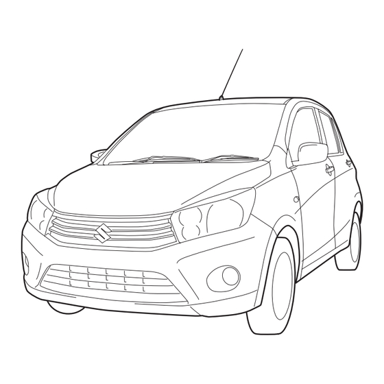
This owner's manual applies to the CELERIO series.
76MH0A016
NOTE: The illustrated model is one of the CELERIO series.
© 2014
All rights reserved.
No part of this document may be reproduced or transmitted in any form or by any means, electronic or
mechanical, for any purpose, without the express written permission of Suzuki Motor Corporation.
84MS0-14E
Advertisement
Chapters
Table of Contents

Subscribe to Our Youtube Channel
Related Manuals for Suzuki CELERIO 2014 Series


Summary of Contents for Suzuki CELERIO 2014 Series
- Page 1 NOTE: The illustrated model is one of the CELERIO series. © 2014 All rights reserved. No part of this document may be reproduced or transmitted in any form or by any means, electronic or mechanical, for any purpose, without the express written permission of Suzuki Motor Corporation. 84MS0-14E...
- Page 2 Please read this manual carefully cial information, the symbol and the tion in this manual and your vehicle. before operating your new SUZUKI and words WARNING, CAUTION, NOTICE SUZUKI MOTOR CORPORATION review the manual from time to time. It con- and NOTE have special meanings.
- Page 3 CB (Citizen’s Band) radios may cause electronic interfer- ence with your vehicle’s ignition sys- tem, resulting in vehicle performance problems. Consult your SUZUKI dealer or qualified service technician for advice on installing such mobile communication equipment. 84MS0-14E...
- Page 4 INTRODUCTION Thank you for choosing SUZUKI and welcome to our growing family. Your choice was a wise one; SUZUKI products are a great value that will give you years of driving pleasure. This Owner’s Manual was prepared to help you have a safe, enjoyable, and trouble-free experience with your SUZUKI. In it you will learn about the vehicle’s operation, its safety features and maintenance requirements.
- Page 5 A wide variety of non-genuine replacement parts and accessories for SUZUKI vehicles are currently available in the market. Using these parts and accessories can affect the vehicle performance and shorten its useful life. Therefore, installation of non-genuine SUZUKI parts and accessories is not covered under warranty.
- Page 6 SERVICE STATION GUIDE 1. Fuel (see section 1) 2. Engine hood (see section 5) 3. Tire changing tools (see section 8) 4. Engine oil dipstick <Yellow> (see section 7) 5. CVT fluid dipstick <Red> (see section 7) 6. Engine coolant (see section 7) 7.
- Page 7 MEMO 84MS0-14E...
-
Page 8: Table Of Contents
TABLE OF CONTENTS FUEL RECOMMENDATION BEFORE DRIVING OPERATING YOUR VEHICLE DRIVING TIPS OTHER CONTROLS AND EQUIPMENT VEHICLE LOADING AND TOWING INSPECTION AND MAINTENANCE EMERGENCY SERVICE APPEARANCE CARE GENERAL INFORMATION SPECIFICATIONS INDEX 84MS0-14E... - Page 9 ILLUSTRATED TABLE OF CONTENTS EXTERIOR, FRONT EXAMPLE 1. Engine Hood (P. 5-2) 2. Windshield Wiper (P.2-50) 3. Radio Antenna (P.5-18) 4. Headlight (P.2-47, 7-30) 5. Outside Rearview Mirror (P.2-10) 6. Door Locks (P.2-2) 84MS0T002 84MS0-14E...
- Page 10 ILLUSTRATED TABLE OF CONTENTS EXTERIOR, REAR EXAMPLE 1. High-mount Stop Light (P. 7-34) 2. Rear Window Wiper (if equipped) (P.2-51) 3. Fuel Filler Cap (P.5-1) 4. Rear Combination Light (P.7-32) 5. Tailgate (P.2-4) 6. License Plate Light (P.7-33) 76MH0A018 84MS0-14E...
- Page 11 ILLUSTRATED TABLE OF CONTENTS INTERIOR, FRONT EXAMPLE 1. Sun Visor (P. 5-3) 2. Front Passenger’s Front Air Bag (if equipped) (P.2-24) 3. Front Interior Light (P.5-4, 7-35) 4. Inside Rearview Mirror (P.2-9) 5. Electric Window Controls (if equipped) (P.2-8)/ Electric Mirrors Control Switch (if equipped) (P.2-10) 6.
- Page 12 ILLUSTRATED TABLE OF CONTENTS 1. Hazard Warning Switch (P.2-50) VIEW A EXAMPLE 2. Audio (if equipped) (P.5-19) 3. Instrument Cluster (P.2-31)/ Information Display (P.2-34) 4. Windshield Wiper and Washer Lever (P.2-50)/ Rear Window Wiper and Washer Switch (if equipped) (P.2-51) 5.
- Page 13 ILLUSTRATED TABLE OF CONTENTS 1. Ignition Switch (P.3-3) VIEW B EXAMPLE 2. Lighting Control Lever (P.2-47)/ Turn Signal Control Lever (P.2-48) 3. Tilt Steering Lock Lever (if equipped) (P.2-52) 4. Fuel Lid Opener Lever (P.5-1) 5. Engine Hood Release Handle (P.5-2) 84MS0T005 84MS0-14E...
- Page 14 ILLUSTRATED TABLE OF CONTENTS INTERIOR, REAR EXAMPLE 1. Seat Belts (P.2-13) 2. Assist Grip (P.5-6) 3. Rear Seats (P.2-12) 84MS0T006 84MS0-14E...
- Page 15 ILLUSTRATED TABLE OF CONTENTS LUGGAGE COMPARTMENT EXAMPLE 1. Luggage Compartment Cover (if equipped) (P.5-9) 2. Spare Tire (P.8-1) 3. Jack Handle (P.8-1) 4. Jack (P.8-1) 5. Wheel Brace (P.8-1) 6. Shopping Hook (P.5-9) 84MS0T007 84MS0-14E...
- Page 16 FUEL RECOMMENDATION FUEL RECOMMENDATION Fuel Recommendation ............1-1 65D394 84MS0-14E...
- Page 17 FUEL RECOMMENDATION If the “RON 95” label is attached, you must Fuel Recommendation use unleaded gasoline with an octane NOTICE number (RON) of 95 or higher. Be careful not to spill fuel containing alcohol while refueling. If fuel is Gasoline/Ethanol blends spilled on the vehicle body, wipe it up Blends of unleaded gasoline and ethanol immediately.
-
Page 18: Before Driving
BEFORE DRIVING BEFORE DRIVING Keys ..................2-1 Door Locks ................2-2 Keyless Entry System Transmitter (if equipped) ..... 2-5 Theft Deterrent Light ............2-7 Windows ................2-7 Mirrors .................. 2-9 Front Seats ................2-10 Rear Seats ................2-12 Seat Belts and Child Restraint Systems ......2-13 Supplemental Restraint System (air bags) ....... -
Page 19: Keys
• If you lose your immobilizer ignition key, EXAMPLE engine starting system. see your SUZUKI dealer as soon as pos- The engine can be started only with your sible to have the lost one deactivated, vehicle’s original immobilizer ignition key then have the new key made by them. -
Page 20: Door Locks
BEFORE DRIVING To unlock a driver’s door from outside the Central Door Locking System Door Locks vehicle, insert the key and turn the top of (if equipped) the key toward the rear of the vehicle. To lock a front passenger’s door from out- Driver’s door Side Door Locks side the vehicle, turn the lock knob for-... - Page 21 BEFORE DRIVING top of the key toward the rear of the vehicle NOTE: Child-Proof Locks (rear door) twice. If your vehicle is equipped with keyless entry system, you can also lock or unlock NOTE: all doors by operating the transmitter. EXAMPLE You can switch the function that unlocks all Refer to “Keyless Entry System Transmit-...
- Page 22 4) Push open the tailgate from inside. The tailgate will be latched again when closing it. If the tailgate cannot be unlatched by pull- ing up the tailgate handle (3), have the vehicle inspected by your SUZUKI dealer. EXAMPLE CAUTION 76MH0A086 (1) Driver’s door lock...
-
Page 23: Keyless Entry System Transmitter (If Equipped)
• If the interior light switch is in the • If you lose one of the transmitters, ask “DOOR” position, the interior light will your SUZUKI dealer as soon as possible turn on for about 15 seconds and then for a replacement. Be sure to have your fade out. - Page 24 BEFORE DRIVING Replacement of the Battery If the transmitter becomes unreliable, WARNING replace the battery. Swallowing a lithium battery may To replace the battery of the transmitter: cause serious internal injury. Do not allow anyone to swallow a lithium battery. Keep lithium batteries away from children and pets.
-
Page 25: Theft Deterrent Light
BEFORE DRIVING This light will blink with the ignition switch Theft Deterrent Light Windows in the “LOCK” or “ACC” position. The blink- ing light is intended to deter theft by lead- ing others to believe that the vehicle is With tachometer equipped with a security system. - Page 26 BEFORE DRIVING Passenger’s door Electric Window Controls EXAMPLE (if equipped) CLOSE The electric windows can only be operated when the ignition switch is in the “ON” posi- tion. Driver’s door OPEN EXAMPLE 81A009 76MH0A023 To open a window, push the top part of the The passenger’s door has a switch (3) to switch and to close the window, lift up the operate that passenger’s window.
-
Page 27: Mirrors
BEFORE DRIVING Lock switch Mirrors WARNING EXAMPLE • You should always lock the passen- ger’s window operation when there Inside Rearview Mirror are children in the vehicle. Children can be seriously injured if they get You can adjust the inside rearview mirror part of their body caught by the by hand so as to see the rear of your vehi- window during operation. -
Page 28: Front Seats
BEFORE DRIVING Outside Rearview Mirrors Electric Mirrors (if equipped) Front Seats Adjust the outside rearview mirrors so you can just see the side of your vehicle in the EXAMPLE Seat Adjustment mirrors. WARNING WARNING Be careful when judging the size or Never attempt to adjust the driver’s distance of a vehicle or other object seat or seatback while driving. - Page 29 BEFORE DRIVING Seat position adjustment lever (1) Pull the lever up and slide the seat. EXAMPLE Seatback angle adjustment lever (2) Pull the lever up and move the seatback. After adjustment, try to move the seat and seatback forward and rearward to ensure that it is securely latched.
-
Page 30: Rear Seats
BEFORE DRIVING Rear Seats NOTICE NOTICE • When you move a seatback, make After folding the rear seatback for- sure the latch plate is inserted into ward, do not allow any foreign mate- Folding Rear Seats the slit securely so the seat belts rial to enter the lock opening. -
Page 31: Seat Belts And Child Restraint Systems
BEFORE DRIVING To return the seat to the normal position, After returning the seat, try moving the Seat Belts and Child Restraint follow the procedure below. seatback to make sure they are securely latched. Systems WARNING CAUTION When returning the rear seatback to the normal position, make sure that Do not put your hand into the rear there is nothing around the striker. - Page 32 BEFORE DRIVING as low as possible across the hips Above the pelvis Across the pelvis 65D606 65D201 65D199 WARNING WARNING WARNING • Never allow persons to ride in the (Continued) (Continued) cargo area of a vehicle. In the event • Seat belts should never be worn •...
- Page 33 BEFORE DRIVING Lap-Shoulder Belt WARNING WARNING (Continued) (Continued) Emergency Locking Retractor (ELR) • Never use the same seat belt on • For children, if the shoulder belt The seat belt has an emergency locking more than one occupant and never irritates the neck or face, move the retractor (ELR), which is designed to lock attach a seat belt over an infant or...
- Page 34 BEFORE DRIVING All Seat Belts Except Rear Center All seat belts except rear center are the Low on hips lap-shoulder belt. 60A040 60A039 To reduce the risk of sliding under the belt To unfasten the seat belt, push the button during a collision, position the lap portion on the buckle and retract the belt slowly of the belt across your lap as low on your...
- Page 35 BEFORE DRIVING To unfasten the belt, press the release but- Rear Center Seat Belt ton on the buckle catch. TO LOOSEN Rear center seat belt is the lap belt. To fasten the belt, pull the latch plate attached to the seat belt across your hips and press it straight into the buckle until you hear a “click”.
- Page 36 BEFORE DRIVING When the driver doesn’t buckle his or her Driver’s Seat Belt Reminder Seat Belt Hanger seat belt with the ignition switch in the “ON” position, the driver’s seat belt reminder With tachometer light in the instrument cluster will blink until EXAMPLE the driver’s seat belt is buckled.
- Page 37 BEFORE DRIVING Seat Belt Inspection Child Restraint Systems WARNING Be sure to inspect all seat belt EXAMPLE assemblies after any collision. Any seat belt assembly which was in use during a collision (other than a very minor one) should be replaced, even if damage to the assembly is not obvious.
- Page 38 BEFORE DRIVING Child restraint SUZUKI highly recommends that you use a child restraint system to restrain infants EXAMPLE and small children. Many different types of child restraint systems are available; make sure that the restraint system you select meets applicable safety standards.
- Page 39 BEFORE DRIVING Installation with Lap-Shoulder Seat WARNING Belts If you install a child restraint system in the rear seat, slide the front seat ELR type belt far enough forward so that the child’s EXAMPLE feet do not touch the front seatback. This will help avoid injury to the child in the event of an accident.
- Page 40 This section of the owner’s manual the seat belts are fastened. For precau- Please refer to the “Seat Adjustment” sec- describes your SUZUKI’s SEAT BELT tions and general information including tion and the instructions and precautions PRETENSIONER SYSTEM.
- Page 41 SUZUKI dealer as soon as possible. To prevent damage or unintended activa- If the “AIR BAG” light on the instrument tion of the pretensioners, be sure the bat-...
- Page 42 System (air bags) WARNING This section of the owner’s manual describes the protection provided by your SUZUKI’s SUPPLEMENTAL RESTRAINT SYSTEM (air bags). Please read and follow ALL these instructions carefully to minimize your risk of severe injury or death in the event of a collision.
- Page 43 (or the seat belt pretensioner system (if seat belts are needed to restrain occu- equipped)) may not work properly. Have pants from further movements during the the air bag system inspected by an autho- accident. rized SUZUKI dealer as soon as possible. 2-25 84MS0-14E...
- Page 44 BEFORE DRIVING Therefore, an air bag is NOT a substitute Front passenger’s front air bag for seat belts. To maximize your protection, (if equipped) ALWAYS WEAR YOUR SEAT BELTS. Be EXAMPLE aware that no system can prevent all pos- sible injuries that may occur in an accident. Driver’s front air bag EXAMPLE 58MS030...
- Page 45 BEFORE DRIVING Conditions of front air bags deployment Conditions of front air bags may inflate (inflation) Receiving a strong impact to the lower body of your vehicle, the front air bags will inflate in many cases. 80J101 • Landing hard or falling 80J097 •...
- Page 46 BEFORE DRIVING Front air bags may not inflate The front air bags may not inflate when the impact is absorbed since the collision object moved, vehicle body deformed, or collision angle was greater than about 30 degrees from the front. 80J119 80J104 •...
- Page 47 BEFORE DRIVING in this section for details on proper seat How the system works and seat belt adjustments. In a frontal collision, the crash sensors will detect rapid deceleration, and if the con- troller judges that the deceleration repre- sents a severe frontal crash, the controller will trigger the inflators.
- Page 48 SUZUKI dealer as soon as possible. board. In these situations, the out- If your vehicle ever gets in deep water and of-position occupant would be too the driver’s floor is submerged, the air bag...
-
Page 49: Instrument Cluster
BEFORE DRIVING Instrument Cluster 1. Speedometer 2. Tachometer (if equipped) 3. Information display 4. Trip meter selector knob 5. Indicator selector knob 6. Warning and indicator lights With tachometer EXAMPLE 84MS0T210 2-31 84MS0-14E... - Page 50 BEFORE DRIVING Without tachometer EXAMPLE 84MS0T219 2-32 84MS0-14E...
-
Page 51: Speedometer
BEFORE DRIVING When the ignition switch is in the “ON” Speedometer Fuel Gauge position, this gauge gives an approximate indication of the amount of fuel in the fuel The speedometer indicates vehicle speed. With tachometer tank. “F” stands for full and “E” stands for empty. -
Page 52: Brightness Control
BEFORE DRIVING Brightness Control Information Display WARNING If you attempt to adjust the display while driving, you could lose control EXAMPLE EXAMPLE of the vehicle. Do not attempt to adjust the display while driving. NOTE: • If you do not turn the brightness control knob within about 5 seconds of activat- ing the brightness control display, the brightness control display will be can-... - Page 53 BEFORE DRIVING without tachometer NOTE: Clock When you reconnect the negative (–) ter- EXAMPLE minal to the battery, the clock indication will When the ignition switch is in the “ON” be reinitialized. Change the indication position, the display (A) shows the time. again to your preference.
- Page 54 BEFORE DRIVING (a) Trip meter A Trip meter (b) Trip meter B The trip meter can be used to measure the EXAMPLE (c) Odometer distance traveled on short trips or between (d) Instantaneous fuel consumption fuel stops. (e) Average fuel consumption You can use the trip meter A or trip meter B (f) Driving range independently.
- Page 55 BEFORE DRIVING Instantaneous Fuel Consumption Average fuel consumption To change the unit of average fuel con- The display shows the value of instanta- If you selected average fuel consumption sumption, while pushing and holding the neous fuel consumption only when the the last time you drove the vehicle, the dis- trip meter selector knob (1), turn the indi- vehicle is moving.
- Page 56 BEFORE DRIVING Driving range Transaxle selector position indica- If you selected driving range the last time tor (for CVT vehicles) you drove the vehicle, the display indicates “---” for a few seconds and then indicates the current driving range when the ignition EXAMPLE switch is turned to the “ON”...
- Page 57 BEFORE DRIVING Setting Mode In the setting mode, you can set up the following functions. Indication Functions Central door locking system “d1” Additional flashes of the turn signal “L2” Initialization setting “de-on” Exit the setting mode “End” 2-39 84MS0-14E...
- Page 58 BEFORE DRIVING Central door locking system “d1” Turn the indicator selector knob • d1-SL1: Unlock all doors by turning the EXAMPLE (2). key or pushing the keyless entry system transmitter once • d1-SL2: Unlock all doors by turning the key or pushing the keyless Push the indicator selector entry system transmitter twice knob (2).
-
Page 59: Warning And Indicator Lights
Brake System Warning Light If the brake system warning light comes on your SUZUKI dealer to inspect the while you are driving the vehicle, it may brake system. mean that there is something wrong with •... - Page 60 BEFORE DRIVING If one of these happens, have the system “AIR BAG” Light Anti-Lock Brake System (ABS) inspected by your SUZUKI dealer. Warning Light (if equipped) If the ABS becomes inoperative, the brake system will function as an ordinary brake system that does not have this ABS sys- tem.
- Page 61 CVT is running, there is the problem with the system. Ask your SUZUKI dealer to have continuously variable transaxle system. the system inspected. Ask your SUZUKI dealer to have the sys- tem inspected. 2-43 84MS0-14E...
- Page 62 Check the oil level and add oil if necessary. If there is enough oil, the lubrication sys- NOTE: tem should be inspected by your SUZUKI Following operations of the steering wheel dealer before you drive the vehicle again. while parking or driving at a very low-...
- Page 63 This light stays on while the engine is still cold and goes off when the engine has warmed up. If this light blinks, there is a problem with the system. Have your vehicle inspected by your SUZUKI dealer. 2-45 84MS0-14E...
- Page 64 “ON” position, there may be ple, slope or curve) and driving conditions something wrong with your key or with the because of fuel moving in the tank. immobilizer system. Ask your SUZUKI dealer to inspect the system. 2-46 84MS0-14E...
-
Page 65: Lighting Control Lever
“ON” position, there is the problem with the signal lights. 65D611 electrical control system. Ask your SUZUKI dealer to have the sys- Main Beam (high beam) Indicator tem inspected. WARNING Light... -
Page 66: Turn Signal Control Lever
BEFORE DRIVING Lighting Operation Turn Signal Control Lever EXAMPLE EXAMPLE 60MK012 With the headlights on, push the lever for- 60MK011 ward to switch to the high beams (main 65D611 beams) or pull the lever toward you to To turn the lights on or off, twist the knob switch to the low beams. - Page 67 With the ignition switch in the “ON” posi- and its indicator. Please ask an authorized tion, move the lever up or down to activate SUZUKI dealer for the customization. the right or left turn signals. Normal turn signal EXAMPLE...
-
Page 68: Hazard Warning Switch
BEFORE DRIVING Windshield Wipers Hazard Warning Switch Windshield Wiper and Washer Lever EXAMPLE EXAMPLE 84MS0T215 84MS0T214 To turn the windshield wipers on, move the Push in the hazard warning switch to acti- lever down to one of the three operating 65D611 vate the hazard warning lights. - Page 69 BEFORE DRIVING Windshield Washer Rear Window Wiper/Washer Switch NOTICE (if equipped) To help prevent damage to the wind- shield wiper and washer system EXAMPLE components, you should take the fol- lowing precautions: Washer • Do not continue to hold in the lever when there windshield...
-
Page 70: Tilt Steering Lock Lever (If Equipped)
BEFORE DRIVING Tilt Steering Lock Lever NOTICE WARNING (if equipped) Clear ice or snow from the rear win- Never attempt to adjust the steering dow and rear wiper blade before wheel height while the vehicle is using the rear wiper. Accumulated ice moving or you could lose control of or snow could prevent the wiper EXAMPLE... -
Page 71: Horn
BEFORE DRIVING Horn EXAMPLE 68LM240 Press the horn button of the steering wheel to sound the horn. The horn will sound with the ignition switch in any position. 2-53 84MS0-14E... -
Page 72: Operating Your Vehicle
OPERATING YOUR VEHICLE OPERATING YOUR VEHICLE Exhaust Gas Warning ............3-1 Daily Inspection Checklist ..........3-1 Engine Oil Consumption ............ 3-2 Ignition Switch ..............3-3 Parking Brake Lever ............3-5 Pedal ..................3-6 Starting the Engine ............. 3-7 Using the Transaxle ............3-8 Braking ................. -
Page 73: Exhaust Gas Warning
OPERATING YOUR VEHICLE Exhaust Gas Warning Daily Inspection Checklist WARNING (Continued) • Do not park with the engine run- Before Driving ning for a long period of time, even in an open area. If it is necessary to sit for a short time in a parked vehi- cle with the engine running, make sure the air intake selector is set to “FRESH AIR”... -
Page 74: Engine Oil Consumption
OPERATING YOUR VEHICLE NOTE: releasing the secondary latch. Be sure Engine Oil Consumption It is normal for water to drip from the air to close the hood securely after check- conditioning system after use. ing for proper latch operation. See “All latches, hinges &... -
Page 75: Ignition Switch
OPERATING YOUR VEHICLE becoming diluted with fuel or moisture, Ignition Switch making it appear that the oil level has not EXAMPLE changed. You should also be aware that the diluting ingredients evaporate out when the vehicle is subsequently driven at high speeds, such as on an expressway, making it appear that oil is excessively consumed after high-speed driving. - Page 76 To release the steering lock, insert the key SUZUKI dealer. and turn it clockwise to one of the other • Do not leave the ignition switch in positions. If you have trouble turning the the “ON” position if the engine is...
-
Page 77: Parking Brake Lever
The parking brake lever is located between first gear. rized SUZUKI dealer. the seats. To set the parking brake, hold CVT – shift into “P” (Park) and the brake pedal down and pull the parking turn off the engine. -
Page 78: Pedal
OPERATING YOUR VEHICLE Parking Brake Reminder Buzzer Clutch Pedal (1) Pedal A buzzer sounds intermittently to remind (For manual transaxle) you to release the parking brake if you The clutch pedal is used to disengage the Manual transaxle start the vehicle without releasing the park- drive to the wheels when starting the EXAMPLE ing brake. -
Page 79: Starting The Engine
Starting the Engine CVT vehicles have a starter interlock device which is designed to keep the Your SUZUKI vehicle is equipped with front starter from operating if the transaxle is in disc brakes and rear drum brakes. any of the drive positions. -
Page 80: Using The Transaxle
OPERATING YOUR VEHICLE Downshifting maximum allowable speeds Starting a Cold and Warm Engine Using the Transaxle For K10B engine With your foot off the accelerator pedal, crank the engine by turning the ignition key Downshifting km/h (mph) Manual Transaxle to “START”. Release the key when the 2nd to 1st 40 (25) engine starts. - Page 81 OPERATING YOUR VEHICLE S (sport) mode switch Continuously Variable Transaxle WARNING The sport mode switch (1) is used to turn (CVT) on and off the sport mode. • Reduce your speed and downshift To turn on the sport mode, push in the to a lower gear before going down switch and sport mode indicator (2) will a long or steep hill.
- Page 82 OPERATING YOUR VEHICLE Gearshift lever P (Park) Shift with the knob button (1) Use this position to lock the transaxle pushed in and the brake pedal when the vehicle is parked or when start- depressed. ing the engine. Shift into Park only when the vehicle is completely stationary.
- Page 83 OPERATING YOUR VEHICLE NOTE: 4) With the release button (1) pushed, If You Cannot Shift CVT Gearshift If you move the gearshift lever to a lower push the knob button (2) and shift the Lever Out of “P” (PARK) gear while driving faster than the maximum gearshift lever to the desired position.
-
Page 84: Braking
OPERATING YOUR VEHICLE Power-Assisted Brakes Braking WARNING Your vehicle has power-assisted brakes. If If water gets into the brake drums, power assistance is lost due to a stalled brake performance may become poor EXAMPLE engine or other failures, the system is still and unpredictable. - Page 85 ABS will still offer the advantage of be a problem with the ABS system. helping you maintain directional Ask your SUZUKI dealer to inspect control. However, remember that the ABS system immediately. If the ABS will not compensate for bad...
- Page 86 The ABS may not work properly if braking even on a dry paved road. tires or wheels other than those Ask your SUZUKI dealer to inspect specified in the owner’s manual are the ABS system immediately. Drive used. This is because the ABS works...
- Page 87 OPERATING YOUR VEHICLE MEMO 3-15 84MS0-14E...
-
Page 88: Driving Tips
DRIVING TIPS DRIVING TIPS Running-in ................4-1 Catalytic Converter ............. 4-1 Improving Fuel Economy ........... 4-2 Highway Driving ..............4-3 Driving on Hills ..............4-3 Driving on Slippery Roads ..........4-4 60G409 84MS0-14E... -
Page 89: Running-In
DRIVING TIPS Running-in Catalytic Converter NOTICE The future performance and reliabil- ity of the engine depends on the care 52D078S and restraint exercised during its early life. It is especially important to observe the following precautions WARNING during the initial 960 km (600 miles) •... -
Page 90: Improving Fuel Economy
DRIVING TIPS damage to the catalyst and other vehicle Improving Fuel Economy components. NOTICE The following instructions will help you improve fuel economy. To avoid damaging catalyst or other Avoid excessive idling vehicle damage: If you are to wait for more than a minute •... -
Page 91: Highway Driving
DRIVING TIPS Keep the air cleaner clean Highway Driving Driving on Hills EXAMPLE When driving at highway speeds, pay attention to the following: • Stopping distance progressively increases with vehicle speed. Apply the brakes far enough ahead of the stopping point to allow for the extra stopping dis- tance. -
Page 92: Driving On Slippery Roads
DRIVING TIPS Tire Chains (if equipped) Driving on Slippery Roads WARNING Tire chains should only be used if they are Try not to hold the brake pedal down needed to increase traction or are required too long or too often while going by law. - Page 93 Pro- • Do not use tires other than those longed rocking can cause engine specified by SUZUKI. Never use dif- 1) Shift the transaxle back and forth overheating or transaxle damage. ferent sizes or types of tires on the between a forward range (or first gear front and rear wheels.
-
Page 94: Other Controls And Equipment
OTHER CONTROLS AND EQUIPMENT OTHER CONTROLS AND EQUIPMENT Fuel Filler Cap ..............5-1 Engine Hood ................ 5-2 Sun Visor ................5-3 Interior Light ................ 5-4 Accessory Socket ............... 5-5 AUX/USB Socket (if equipped) ........... 5-6 Assist Grips ................. 5-6 Glove Box ................5-6 Cup Holder and Storage Area .......... -
Page 95: Fuel Filler Cap
OTHER CONTROLS AND EQUIPMENT The fuel filler cap is located on the left rear Fuel Filler Cap side of the vehicle. The fuel filler door can EXAMPLE be unlocked by pulling up the opener lever located on the outboard side of the driver’s seat and locked by simply closing the door. -
Page 96: Engine Hood
OTHER CONTROLS AND EQUIPMENT Engine Hood WARNING If you need to replace the fuel cap, use a genuine SUZUKI cap. Use of an EXAMPLE improper cap can result in a malfunc- tion of the fuel system or emission control system. It may also result in fuel leakage in the event of an acci- dent. -
Page 97: Sun Visor
OTHER CONTROLS AND EQUIPMENT To close the engine hood: Sun Visor 1) Lift the hood up slightly and remove the prop rod from the hole. Put the prop rod back to the holding clip. 2) Lower the hood close to the bumper, EXAMPLE then let it drop down. -
Page 98: Interior Light
OTHER CONTROLS AND EQUIPMENT Card holder Vanity mirror (if equipped) Interior Light EXAMPLE EXAMPLE EXAMPLE 67LH064 84MS0T520 (1) Card holder (2) Vanity mirror 76MH0A138 You can put a card in the card holder (1) on There is a vanity mirror (2) on the back of the back of the sun visor. -
Page 99: Accessory Socket
OTHER CONTROLS AND EQUIPMENT This light switch has three positions which Accessory Socket function as described below: ON (a) The light comes on and stays on regard- less of whether the door is open or closed. DOOR (b) The light comes on when the door is opened. -
Page 100: Aux/Usb Socket (If Equipped)
OTHER CONTROLS AND EQUIPMENT AUX/USB Socket (if equipped) Assist Grips Glove Box EXAMPLE EXAMPLE 84MS0T502 54G249 76MH0A073 Connect your portable digital music player, Assist grips are provided for convenience. To open the glove box, pull the latch lever. etc. to this socket to enjoy music through To close it, push the lid until it latches the vehicle’s audio system using it as a NOTICE... -
Page 101: Cup Holder And Storage Area
OTHER CONTROLS AND EQUIPMENT Instrument Panel Pocket Cup Holder and Storage Area (driver’s side) (1) / Instrument Panel Pocket (center) (2) EXAMPLE WARNING Do not place any objects which may fall out from the pocket when the vehicle is moving. Failure to take the precaution may result in an object interfering with the pedals and causing a loss of vehicle... -
Page 102: Floor Mats (If Equipped)
When you replace the floor mats in your vehicle with a different type such as all- weather floor mats, we highly recommend using genuine SUZUKI floor mats for proper fitting. 84MS0-14E... -
Page 103: Luggage Compartment Hooks
OTHER CONTROLS AND EQUIPMENT Luggage Compartment Hooks Luggage Compartment Cover WARNING (if equipped) Failure to take the following precau- tions may result in the driver’s side Shopping Hook Luggage or other cargo placed in the lug- floor mat interfering with the pedals gage compartment is hidden from view by and causing a loss of vehicle control a luggage compartment cover. -
Page 104: Frame Hooks
OTHER CONTROLS AND EQUIPMENT Removing the Luggage Frame Hooks Compartment Cover Front EXAMPLE 84MS0T503 2) Remove the Luggage compartment cover (2) as shown in the illustration. 84MS0T521 1) Remove the straps (1). Installing the Luggage 76MH0A077 Compartment Cover The frame hook (1) is provided on the front of the vehicle for use in emergency situa- Install the luggage compartment cover in tions and trailer/train/sea shipping pur-... - Page 105 OTHER CONTROLS AND EQUIPMENT Rear WARNING WARNING Do not use the frame hooks to tow Do not use the frame hooks to tow another vehicle or to have your vehi- another vehicle or to have your vehi- cle towed on the road or highway. cle towed on the road or highway.
- Page 106 OTHER CONTROLS AND EQUIPMENT Other Hooks EXAMPLE 84MS0T522 The frame holes (3) are provided for trailer/ train shipping purposes only. 5-12 84MS0-14E...
-
Page 107: Manual Heating And Air Conditioning System
OTHER CONTROLS AND EQUIPMENT Side outlet Manual Heating and Air Conditioning System EXAMPLE 84MS0T504 76MH0A118 1. Windshield defroster outlet When “Open”, air comes out regardless of 2. Side defroster outlet the air flow selector position. 3. Side outlet 4. Center outlet 5. - Page 108 OTHER CONTROLS AND EQUIPMENT Center outlet Description of Controls 76MH0A081 Move the knob (1) vertically or horizontally to adjust the direction of airflow as desired. 84MS0T505 Temperature selector with air condition- ing switch (1) This is used to select the temperature by turning the selector.
- Page 109 OTHER CONTROLS AND EQUIPMENT NOTE: Ventilation (a) Foot (c) During operation of the air conditioner, you may notice slight changes in engine speed. These changes are normal, the system is designed so that the compressor turns on or off to maintain the desired tem- perature.
- Page 110 OTHER CONTROLS AND EQUIPMENT Defrost (e) Air intake selector (4) System Operating Instructions Natural ventilation Select “VENTILATION” and “FRESH AIR”, the temperature selector to the desired temperature position, and the blower speed selector to “OFF”. Fresh air will flow through the vehicle during driving. 76MH0A088 76MH0A089 Temperature-controlled air comes out of...
- Page 111 OTHER CONTROLS AND EQUIPMENT Quick cooling (using recirculated air) Dehumidifying Maintenance The control settings are the same as for Set the air flow selector to a desired air normal cooling except you select “RECIR- flow selector position, the temperature If you do not use the air conditioner for a CULATED AIR”...
-
Page 112: Radio Antenna
Installation of Radio Frequency Transmitters EXAMPLE We recommend that you always ask a SUZUKI dealer about frequency band, max output power, antenna position at vehicle and specific conditions for installa- tion and/or use before installing a radio transmitter in your vehicle. Such equip-... -
Page 113: Audio System (If Equipped)
OTHER CONTROLS AND EQUIPMENT Audio System (if equipped) AM/FM CD PLAYER 5-19 84MS0-14E... - Page 114 Please bring the unit to an authorized SUZUKI dealer. sets. • Set the sound volume to a level that will allow you to continue to be...
- Page 115 OTHER CONTROLS AND EQUIPMENT To remove fingermarks and dust, use a Never stick labels on the surface of the Do not expose compact discs to direct sun- soft cloth, and wipe in a straight line from compact disc or write on the surface with a light or any heat source.
- Page 116 OTHER CONTROLS AND EQUIPMENT WARNING This is a class I laser product. Use of controls or adjustments or perfor- mance of procedures other than those specified herein may result in hazardous radiation exposure. Do not open covers and do not attempt to repair this unit by yourself.
- Page 117 OTHER CONTROLS AND EQUIPMENT Turning power on/off Basic Operations Press the VOL PUSH POWER knob (1). The unit starts in the function mode it was in when the power was turned off last. Adjusting the volume Turn the VOL PUSH POWER knob (1). Turning it clockwise increases the volume;...
- Page 118 OTHER CONTROLS AND EQUIPMENT Adjusting bass/treble/balance /fader Adjusting the AVC (Auto volume con- Preset-EQ 1) Press the SOUND button (2). trol) Preset-EQ calls up various sound types in Each time the button is pressed, sound The Auto Volume Control (AVC) function accordance with the listening music type.
- Page 119 OTHER CONTROLS AND EQUIPMENT Display Listening to the Radio (1) FM/AM button (2) SEEK Up button (3) SEEK Down button (4) TUNE Up button (5) TUNE Down button (6) Preset buttons ([1] to [6]) (7) AS button (A) Band (B) Frequency 5-25 84MS0-14E...
- Page 120 OTHER CONTROLS AND EQUIPMENT Selecting the reception band Auto store Radio Reception Press the FM/AM button (1). Hold down the AS button (7) for 2 seconds Radio reception can be affected by envi- Each time the button is pressed, the recep- or longer.
- Page 121 OTHER CONTROLS AND EQUIPMENT Display Listening to a CD (1) Insertion slot (2) Eject button (3) MEDIA button (4) TRACK Up button (5) TRACK Down button (6) RPT button (7) RDM button (8) DISP button (A) Track number (B) Play time NOTE: This product does not support 8 cm CD (sometimes called as “mini single CD”, “3-...
- Page 122 OTHER CONTROLS AND EQUIPMENT NOTICE NOTICE • Never insert your finger or hand If you forcefully try to push an ejected into the CD insertion slot. Never CD inside the unit before auto reload- insert foreign objects. ing, the disc surface might be •...
- Page 123 OTHER CONTROLS AND EQUIPMENT Random playback Display change Press the RDM button (7). Press the DISP button (8). Each time the button is pressed, the mode Each time the button is pressed, display will change as follows: will change as follows: Play time TRACK RANDOM Disc title...
- Page 124 OTHER CONTROLS AND EQUIPMENT Display Listening to an MP3/WMA/AAC Disc (1) FOLDER Up button (2) FOLDER Down button (3) TRACK Up button (4) TRACK Down button (5) RPT button (6) RDM button (7) DISP button (A) DISC type (B) Folder number (C) Track number 5-30 84MS0-14E...
- Page 125 OTHER CONTROLS AND EQUIPMENT Selecting a folder Random playback Repeat playback • Press the FOLDER Up button (1) to Press the RDM button (6). Press the RPT button (5). jump to the next folder. Each time the button is pressed, the mode Each time the button is pressed, the mode •...
- Page 126 OTHER CONTROLS AND EQUIPMENT Display change Press the DISP button (7). Each time the button is pressed, display will change as follows: Folder No., Track No. Play time Folder name File name Album name (MP3, AAC only) Track title Artist name NOTE: •...
- Page 127 OTHER CONTROLS AND EQUIPMENT Points to remember when making MP3/ • When storing both MP3 data and WMA Notes on MP3/WMA/AAC WMA/AAC files data on the same disc, sort and place Common them in different folders. What is MP3? • High bit rate and high sampling fre- •...
- Page 128 OTHER CONTROLS AND EQUIPMENT WMA (Ver. 7, Ver. 8, Ver. 9*) • Bit rate: CBR 32 k - 320 kbps • Sampling frequency: 32 k/44.1 k/48 kHz * WMA 9 Professional/LossLess/Voice are not supported. AAC* • Bit rate: ABR 16k - 320 kbbs •...
- Page 129 OTHER CONTROLS AND EQUIPMENT Display Listening to files stored in a USB device (1) MEDIA button (2) FOLDER Up button (3) FOLDER Down button (4) TRACK Up button (5) TRACK Down button (6) RPT button (7) RDM button (8) DISP button (A) Folder number (B) Track number 5-35...
- Page 130 OTHER CONTROLS AND EQUIPMENT Selecting a track NOTICE • Press the TRACK Up button (4) to listen Repeat playback to the next track. Press the RPT button (6). Do not connect any USB device other • Press the TRACK Down button (5) twice Each time the button is pressed, the mode than a USB memory or a USB audio to listen to the previous track.
- Page 131 OTHER CONTROLS AND EQUIPMENT Display change order from the order that the files were Notes on USB device Press the DISP button (8). stored. Each time the button is pressed, display Compatible USB devices will change as follows: Compression formats •...
- Page 132 OTHER CONTROLS AND EQUIPMENT Display ® Listening to an iPod (1) MEDIA button (2) TRACK Up button (3) TRACK Down button (4) RPT button (5) RDM button (6) MENU button (7) ENT button (8) DISP button (9) VOL PUSH POWER knob (A) Track number (B) Play time 5-38...
- Page 133 OTHER CONTROLS AND EQUIPMENT ® Selecting an iPod mode Random playback Display change Press the MEDIA button (1). Press the RDM button (5). Press the DISP button (8). Each time the button is pressed, the mode Each time the button is pressed, the mode Each time the button is pressed, display will change as follows: will change as follows:...
- Page 134 OTHER CONTROLS AND EQUIPMENT ® Playing Mode selection iPod connection ® Notes on iPod ® 1) Press the MENU button (6) for 1 sec- • Make sure to detach the iPod after ® ond or longer. pressing the engine switch to change the Supported iPod ®...
- Page 135 OTHER CONTROLS AND EQUIPMENT AUX connection AUX Function To listen to auxiliary audio sources (sold separately) through the unit, follow the instruction below. 1) Connect the auxiliary audio source to the AUX/USB socket (1) with an AUX cable. 2) Press the MEDIA button (2). Each time the button is pressed, the mode will change as follows: DISK (if inserted CD)
- Page 136 OTHER CONTROLS AND EQUIPMENT NOTE: • Please consult your place of purchase for details about whether a given auxil- iary audio source can be connected and the proper auxiliary cord to use. • The volume and tone controls of the aux- iliary audio source can be adjusted on the unit.
- Page 137 OTHER CONTROLS AND EQUIPMENT (1) VOL PUSH POWER knob Anti-Theft Feature (2) Preset buttons ([1] to [6]) (3) TRACK Up button (4) SOUND button 5-43 84MS0-14E...
- Page 138 OTHER CONTROLS AND EQUIPMENT The anti-theft function is intended to dis- Canceling the anti-theft feature Confirming the Personal Identification courage thefts, such as that the audio sys- To cancel the anti-theft function, delete the Number (PIN) tem becomes inoperable when it is registered PIN.
- Page 139 OTHER CONTROLS AND EQUIPMENT Troubleshooting When encountered a problem, check and follow the instructions as described below. If the described suggestions do not solve the problem, it is recommended to take the unit to your authorized SUZUKI dealer. Problem Possible cause...
- Page 140 OTHER CONTROLS AND EQUIPMENT Problem Possible cause Possible solution MP3/WMA/AAC The disc contains unsupported formatted No playback Check the file format. data. Sound skipping may occur when playing Sound skips or noise produced It is not recommended to play VBR files. VBR (Variable Bit Rate) files.
- Page 141 OTHER CONTROLS AND EQUIPMENT Error Display Messages Display Possible cause Possible solution Insert the disc with its label side up. Check the disc if it is not warped or is free of flaws. ERROR 1 The disc cannot be read. When ERROR 1 does not disappear even when a normal disc is inserted, contact your dealer.
-
Page 142: Vehicle Loading And Towing
VEHICLE LOADING AND TOWING VEHICLE LOADING AND TOWING Vehicle Loading ..............6-1 Trailer Towing ..............6-1 Towing Your Vehicle (recreational towing) ...... 6-2 54G215 84MS0-14E... - Page 143 Gross cargo, not to tow a trailer. SUZUKI does pants, accessories, cargo plus trailer Vehicle Weight Rating (GVWR) and the...
- Page 144 VEHICLE LOADING AND TOWING TOWING INSTRUCTION TABLE Towing Your Vehicle DRIVE TRAN- TOWING (recreational towing) TRAIN SAXLE METHOD Your vehicle may be towed behind another vehicle (such as a motorhome), provided your vehicle is 2 wheel drive (2WD) and you use the proper towing method speci- fied for your vehicle.
- Page 145 VEHICLE LOADING AND TOWING A: 2WD VEHICLES WITH MANUAL TRANSAXLE OR CVT TOWING METHOD A 1) Secure the front wheels on a towing FROM THE FRONT: dolly according to the instructions pro- FRONT WHEELS ON A DOLLY vided by the dolly manufacturer. AND REAR WHEELS ON THE GROUND 2) Release the parking brake.
- Page 146 VEHICLE LOADING AND TOWING B: 2WD VEHICLES WITH MANUAL TRANSAXLE TOWING METHOD B 1) Shift the gearshift lever into neutral. FROM THE FRONT: 2) Turn the ignition key to the “ACC” posi- FOUR WHEELS ON THE GROUND tion to unlock the steering wheel. 3) Release the parking brake.
- Page 147 VEHICLE LOADING AND TOWING MEMO 84MS0-14E...
-
Page 148: Inspection And Maintenance
INSPECTION AND MAINTENANCE INSPECTION AND MAINTENANCE Maintenance Schedule ............7-2 Periodic Maintenance Schedule ........7-2 Maintenance Recommended under Severe Driving Conditions ................7-7 Drive Belt ................7-11 Engine Oil and Filter ............7-11 Engine Coolant ..............7-15 Air Cleaner ................7-17 Spark Plugs ................. - Page 149 90 seconds the engine or when the engine is before performing any electrical running, or you could receive an service work on your SUZUKI. Do electric shock. not touch air bag system compo- • Be careful not to touch a hot...
-
Page 150: Maintenance Schedule
This table shows in miles, “I” : Inspect, clean, adjust, lubricate authorized SUZUKI dealer or a quali- kilometers and months when you should or replace as necessary fied service technician. If you are perform inspections, adjustments, lubrica- qualified, you may perform mainte- tion and other services. - Page 151 #1: Be sure to perform the engine coolant level check under the daily inspection in “OPERATING YOUR VEHICLE” section. If you replace the engine coolant other than SUZUKI LLC: Super (Blue), follow the schedule of SUZUKI LLC: Standard (Green). 84MS0-14E...
- Page 152 #1: Be sure to perform the engine coolant level check under the daily inspection in “OPERATING YOUR VEHICLE” section. If you replace the engine coolant other than SUZUKI LLC: Super (Blue), follow the schedule of SUZUKI LLC: Standard (Green). 84MS0-14E...
- Page 153 *6-6. Manual transaxle oil Genuine “SUZUKI GEAR OIL 75W-80” Inspect every 30000 km (18000 miles) or 24 months Replace every 150000 km (90000 miles) or 120 months Other than “SUZUKI GEAR OIL 75W-80” (I: 1st 15000 km only) – – –...
- Page 154 *6-6. Manual transaxle oil Genuine “SUZUKI GEAR OIL 75W-80” Inspect every 30000 km (18000 miles) or 24 months Replace every 150000 km (90000 miles) or 120 months Other than “SUZUKI GEAR OIL 75W-80” (I: 1st 15000 km only) – – –...
-
Page 155: Maintenance Recommended Under Severe Driving Conditions
#1: Be sure to perform the engine coolant level check under the daily inspection in “OPERATING YOUR VEHICLE” section. If you replace the engine coolant other than SUZUKI LLC: Super (Blue), follow the schedule of SUZUKI LLC: Standard (Green). 84MS0-14E... - Page 156 #1: Be sure to perform the engine coolant level check under the daily inspection in “OPERATING YOUR VEHICLE” section. If you replace the engine coolant other than SUZUKI LLC: Super (Blue), follow the schedule of SUZUKI LLC: Standard (Green). 84MS0-14E...
- Page 157 – – *6-7. Manual transaxle oil Genuine “SUZUKI GEAR OIL 75W-80” Inspect every 30000 km (18000 miles) or 24 months Replace every 60000 km (36000 miles) or 48 months Other than “SUZUKI GEAR OIL 75W-80” – – – – –...
- Page 158 – *6-7. Manual transaxle oil Genuine “SUZUKI GEAR OIL 75W-80” Inspect every 30000 km (18000 miles) or 24 months Replace every 60000 km (36000 miles) or 48 months Other than “SUZUKI GEAR OIL 75W-80” – – – – 6-8. Continuously variable transaxle (CVT) Fluid level –...
-
Page 159: Drive Belt
(0.28 – 0.31 in.) If you need to replace or adjust the belt (1) Preferred have it done by your SUZUKI dealer. Be sure that the engine oil you use comes →: 100 N (10 kg, 22 lbs) press under the quality classification of SL, SM GE: Generator or SN. - Page 160 INSPECTION AND MAINTENANCE Oil Level Check Refilling Upper EXAMPLE Lower EXAMPLE EXAMPLE Open Close 52D084 Pull out the oil dipstick, wipe oil off with a 68KH066 clean cloth, insert the dipstick all the way 84MS0T702 into the engine, then remove it again. The It is important to keep the engine oil at the Remove the oil filler cap and pour oil slowly oil on the stick should be between the...
- Page 161 INSPECTION AND MAINTENANCE Changing Engine Oil and Filter WARNING EXAMPLE Drain the engine oil while the engine is still (Continued) warm. To minimize your exposure to used oil, wear a long-sleeve shirt and EXAMPLE moisture-proof gloves (such as dish- washing gloves) when changing oil. If oil contacts your skin, wash thor- Open Close...
- Page 162 • When replacing the oil filter, it is rec- ommended that you use a genuine To prevent oil leakage, make sure Tightening (viewed from filter top) SUZUKI replacement filter. If you that the oil filter is tight, but do not use an aftermarket filter, make sure over-tighten it.
-
Page 163: Engine Coolant
Failure to use the proper coolant can dam- Coolant Level Check Engine Coolant age your cooling system. Your authorized SUZUKI dealer can help you select the Check the coolant level at the reservoir proper coolant. tank, not at the radiator. With the engine... - Page 164 SUZUKI LLC: Super (Blue) coolant; SUZUKI dealer for coolant replacement. reaches the “FULL” mark. Never fill the res- SUZUKI LLC: Super (Blue) coolant is ervoir tank above the “FULL” mark. already diluted to the proper percent- age. Do not dilute with distilled water additionally.
-
Page 165: Air Cleaner
INSPECTION AND MAINTENANCE For nickel spark plugs (traditional type): Air Cleaner Spark Plugs You should inspect spark plugs periodically for carbon deposits. When carbon accu- If the air cleaner is clogged with dust, there mulates on a spark plug, a strong spark will be greater intake resistance, resulting may not be produced. - Page 166 “SPECIFICATIONS” section at the • Never use spark plugs with the end of this book. If you wish to use a wrong thread size. brand of spark plug other than the specified plugs, consult your SUZUKI dealer. 7-18 84MS0-14E...
-
Page 167: Gear Oil
After driving the vehicle, the tran- We highly recommend you use: saxle oil temperature may be high “SUZUKI GEAR OIL 75W-80” for manual enough to burn your skin. Wait until transaxle gear oil. the oil filler plug is cool enough to... -
Page 168: Clutch Pedal
Wait until the fluid cools down Specified Fluid (about 30 minutes), or the fluid level indica- EXAMPLE tion will not be correct. Use a CVT fluid SUZUKI CVT FLUID GREEN-2. EXAMPLE Fluid Level Check NOTICE Driving with too much or too little fluid can damage the transaxle. -
Page 169: Brakes
Changing Oil hot range on the dipstick. Since special procedures, materials, and tools are required to change the CVT oil, it is recommended that you trust this job to your authorized SUZUKI dealer. 7-21 84MS0-14E... - Page 170 If not, have the brake sys- Since your vehicle’s brake system is self- of the brake fluid reservoir. tem inspected by your SUZUKI dealer. If adjusting, there is no need for pedal you doubt the brake pedal for the regular adjustment.
-
Page 171: Steering
• Excessive noise released, have the parking brake inspected wrong, an inspection must be performed • Pedal pulsation (pedal pulsates and/or adjusted by your SUZUKI dealer. by your SUZUKI dealer. when depressed.) 7-23 84MS0-14E... -
Page 172: Tires
3) Check for abnormal wear, cracks and Overinflation also cause damage. Any tires with cracks or other unusual handling characteristics damage should be replaced. If any tires which may result in an accident. show abnormal wear, have them inspected by your SUZUKI dealer. 7-24 84MS0-14E... - Page 173 5) Check that there are no nails, stones or other objects sticking into the tires. Tire Rotation WARNING 4-tire rotation • Your SUZUKI is equipped with tires which are all the same type and 54G115 size. This is important to ensure (1) Wear indicator...
-
Page 174: Battery
INSPECTION AND MAINTENANCE Note that two or more compact spare tires Battery should not be used on one vehicle simulta- EXAMPLE neously. WARNING WARNING The compact spare tire and wheel are • Batteries produce flammable intended for temporary emergency hydrogen gas. Keep flames and use only. -
Page 175: Fuses
INSPECTION AND MAINTENANCE Fuses in the Engine Compartment Fuses MAIN FUSE/PRIMARY FUSE Your vehicle has three types of fuses, as described below: Main fuse The main fuse takes current directly from – Blank the battery. – Blank Primary fuses – Blank (27) These fuses are between the main fuse... - Page 176 When replacing the main fuse, a primary fuse or an individual 60G111 fuse, use a genuine SUZUKI replacement. To remove a fuse, use the fuse puller pro- WARNING 68KH078 vided in the fuse box. The amperage of...
-
Page 177: Bulb Replacement
(19) Dome of time, you may have a major electri- the electrical system. This should be problem. Have your vehicle carried out by your SUZUKI dealer. (20) Power window inspected immediately your (21) – Blank SUZUKI dealer. - Page 178 INSPECTION AND MAINTENANCE 1) Open the engine hood. Disconnect the Headlights coupler (2). Remove the sealing rubber (3). Halogen headlights (1) EXAMPLE 76MH0A115 NOTE: You can see the position of retaining spring 76MH0A114 from the hole of headlight. 76MH0A112 2) Push the retaining spring (4) forward and unhook it.
- Page 179 INSPECTION AND MAINTENANCE Front Turn Signal Light (1) EXAMPLE Front Position Light (2) 76MH0A117 61MM0B078 1) Open the engine hood. To remove the (3) Removal bulb holder of the front turn signal light (4) Install 76MH0A116 (1) or the front position light (2) from the 2) To remove the bulb of the front turn sig- light housing, turn the holder counter- nal light (1) from the bulb holder, push...
- Page 180 INSPECTION AND MAINTENANCE Rear Combination Light EXAMPLE (3) / (4) / (5) 76MH0A122 76MH0A123 2) To remove the bulb holder of the tail/ (6) Removal 76MH0A121 brake light (3), the turn signal light (4) or (7) Install the reversing light (5) from the light 1) Remove the bolts (1) and pull the light 3) To remove the bulb of the tail/brake light housing, turn the holder counterclock-...
- Page 181 INSPECTION AND MAINTENANCE License Plate Light 76MH0A124 76MH0A126 NOTE: 2) To remove and install the bulb of the When reinstalling the light housing, make 76MH0A125 license plate light (2), simply pull out or sure the clips are properly attached. push in the bulb. 1) Turn the cover (1) counterclockwise to remove it.
- Page 182 INSPECTION AND MAINTENANCE High-mount Stop Light EXAMPLE EXAMPLE 76MH0A127 84MS0T704 EXAMPLE 2) Close the tailgate. Remove the high- 3) Pushing the unguiform prongs (3) 80J100 mount stop light housing (2) from the toward inside and remove the bulb tailgate. holder (4). 1) Open the tailgate, and remove the nuts 4) Replace the bulbs.
-
Page 183: Wiper Blades
Remove the lens by using a flat blade vehicle specifications. If so, consult your screwdriver covered with a soft cloth as SUZUKI dealer for proper replacement shown. To install it, simply push it back in. method. For windshield wipers:... - Page 184 INSPECTION AND MAINTENANCE Removal EXAMPLE EXAMPLE 54G135 60A260 (1) Retainer Installation 4) If the new blade is provided without the two metal retainers, move them from the old blade to the new one. EXAMPLE 54G130 2) Squeeze lock (1) towards wiper arm (2) and remove the wiper frame from the 54G132 arm as shown.
- Page 185 INSPECTION AND MAINTENANCE For rear wipers: EXAMPLE 60MH072 65D151 (A) Up NOTE: (B) Down Do not flex the wiper blade frame end more than necessary. If you do, it can break off. NOTE: When you install the metal retainers (3), make sure the direction of metal retainers as shown in the above illustrations.
-
Page 186: Windshield Washer Fluid
INSPECTION AND MAINTENANCE Windshield Washer Fluid NOTICE Damage may result if the washer Front motor is operated with no fluid in the EXAMPLE washer tank. 54G135 (1) Retainer 4) If the new blade is provided without the 80JM078 two metal retainers, move them from Check that there is washer fluid in the tank. -
Page 187: Air Conditioning System
INSPECTION AND MAINTENANCE Air Conditioning System If you do not use the air conditioner for a long period, such as during winter, it may not give the best performance when you start using it again. To help maintain opti- mum performance and durability of your air conditioner, it needs to be run periodically. -
Page 188: Emergency Service
EMERGENCY SERVICE EMERGENCY SERVICE Tire Changing Tool ............. 8-1 Jacking Instructions ............8-1 Changing Wheels ..............8-4 Jump Starting Instructions ..........8-5 Towing .................. 8-6 If the Starter Does Not Operate .......... 8-7 If the Engine is Flooded ............8-7 If the Engine Overheats ............ -
Page 189: Tire Changing Tool
EMERGENCY SERVICE Tire Changing Tool Jacking Instructions EXAMPLE 76MH0A129 To remove the spare tire, turn its bolt (1) counterclockwise and remove it. 52KM119 61MM0B100 WARNING 1) Place the vehicle on level, hard ground. (1) Jack 2) Set the parking brake firmly and shift After using the tire changing tools, (2) Wheel brace into “P”... - Page 190 EMERGENCY SERVICE 3) Turn on the hazard warning flasher if 7) Continue to raise the jack slowly and your vehicle is near traffic. smoothly until the tire clears the 4) Block the front and rear of the wheel ground. Do not raise the vehicle more diagonally opposite of the wheel being than necessary.
- Page 191 EMERGENCY SERVICE Front jacking point for garage jack (1) Rear jacking point for garage jack (2) To Raise the Vehicle with a Garage EXAMPLE Jack • Apply the garage jack to one of the points indicated below. • Always support the raised vehicle with jack stands (commercially available) at the points indicated below.
-
Page 192: Changing Wheels
2) Remove the jack, tools and spare wheel NOTE: from the vehicle. For more details, please contact an autho- 3) Loosen, but do not remove the wheel rized SUZUKI dealer. nuts. 4) Jack up the vehicle (follow the jacking instructions in this section). 54G116... -
Page 193: Jump Starting Instructions
• If your battery discharges repeat- EXAMPLE edly, for no apparent reason, have your vehicle inspected by an autho- rized SUZUKI dealer. • To avoid harm to yourself or dam- age to your vehicle or battery, fol- low the jump starting instructions 54G117 below precisely and in order. -
Page 194: Towing
EMERGENCY SERVICE Towing WARNING Never connect the jump lead directly If you need to have your vehicle towed, to the negative (–) terminal of the dis- contact a professional service. Your dealer charged battery, or an explosion may can provide you with detailed towing occur. -
Page 195: If The Starter Does Not Operate
“ACC” position), and the steering inspected your authorized wheel is secured with a clamping SUZUKI dealer. device designed for towing service. NOTICE The steering column is not strong enough to withstand shocks trans- mitted from the front wheels during towing. -
Page 196: If The Engine Overheats
NOTE: 65D614 WARNING If your engine overheats and you are unsure what to do, contact your SUZUKI WARNING If you see or hear escaping steam, dealer. stop the vehicle in a safe place and • It is hazardous to remove the radia-... - Page 197 EMERGENCY SERVICE MEMO 84MS0-14E...
-
Page 198: Appearance Care
APPEARANCE CARE APPEARANCE CARE Corrosion Prevention ............9-1 Vehicle Cleaning ..............9-2 60G412 84MS0-14E... - Page 199 APPEARANCE CARE 4) High temperatures will cause an accel- Remove foreign material deposits Corrosion Prevention erated rate of corrosion to parts of the Foreign material such as salts, chemicals, vehicle which are not well ventilated to road oil or tar, tree sap, bird droppings and It is important to take good care of your permit quick drying.
- Page 200 APPEARANCE CARE spill or leak does occur, clean and dry the Cleaning the Interior Vehicle Cleaning area immediately. Vinyl upholstery Store your vehicle in a dry, well-venti- Prepare a solution of soap or mild deter- lated area gent mixed with warm water. Apply the Do not park your vehicle in a damp, poorly solution to the vinyl with a sponge or soft ventilated area.
- Page 201 APPEARANCE CARE rinse the mat thoroughly with water and Cleaning the Exterior Washing dry it in the shade. Carpets NOTICE Remove dirt and soil as much as possible It is important that your vehicle be with a vacuum cleaner. Using a mild soap kept clean and free from dirt.
- Page 202 APPEARANCE CARE When washing the vehicle, park it where 2. Stir the paint and “touch-up” the direct sunlight does not fall on it and follow NOTICE damaged spots lightly using a small the instructions below: brush. To avoid damage to the paint or plas- 1) Flush the underside of body and wheel 3.
- Page 203 APPEARANCE CARE Waxing 60B211S After washing the vehicle, waxing and pol- ishing are recommended to further protect and beautify the paint. • Only use waxes and polishes of good quality. • When using waxes polishes, observe the precautions specified by the manufacturers.
-
Page 204: General Information
GENERAL INFORMATION GENERAL INFORMATION Vehicle Identification ............10-1 54G072 84MS0-14E... - Page 205 Whenever you have occasion to consult your SUZUKI dealer, remember to identify your vehicle with this number. Should you find the number difficult to read, you will also find it on the identifica- tion plate.
-
Page 206: Specifications
SPECIFICATIONS SPECIFICATIONS NOTE: Specifications are subject to change with- M/T: Manual transaxle out notice. CVT: Countinuously variable transaxle ITEM: Dimensions UNIT: mm (in.) Overall length 3600 (141.7) Overall width 1600 (63.0) Overall height 1540 (60.6) Wheelbase 2425 (95.5) Track Front 1420 (55.9) Rear 1410 (55.5) - Page 207 SPECIFICATIONS ITEM: Engine Type K10B (DOHC) Number of cylinders Bore 73.0 mm (2.87 in.) Stroke 79.5 mm (3.13 in.) Piston displacement 998 cm (998 cc, 60.9 cu.in) Compression ratio 11.0 : 1 ITEM: Electrical Standard spark plug Nickel plug NGK KR6A-10 Battery 12V 34B19L Fuses...
- Page 208 SPECIFICATIONS ITEM: Lights WATTAGE BULB No. Headlight 12V 60/55W Position light 12V 5W Turn signal light Front 12V 21W PY21W Rear 12V 21W PY21W Side turn signal light 12V 5W WY5W Brake/tail light 12V 21/5W P21/5W High mount stop light 12V 5W Reversing light 12V 21W...
- Page 209 • Mount the snow tires on all four wheels. • Please understand than the maximum permissible speed of snow tires are generally less than the originally installed tires. Consult your SUZUKI dealer or supplier for further information. ITEM: Recommended Fuel/Lubricants and Capacities (approx.) Fuel See “FUEL RECOMMENDATION”...
-
Page 210: Index
INDEX INDEX Catalytic Converter ..............4-1 Central Door Locking System..........2-2 Symbols Changing Engine Oil and Filter...........7-13 “AIR BAG” Light ............2-25, 2-42 Changing Wheels ..............8-4 Charging Light..............2-45 Accelerator Pedal ..............3-7 Chassis Serial Number ............10-1 Accessory Socket..............5-5 Child Restraint Systems............2-19 Adding Coolant .............. - Page 211 INDEX Emergency Locking Retractor (ELR) ......... 2-15 Glove Box ................5-6 Engine Coolant ..............7-15 Engine Coolant Temperature Light........2-45 Halogen headlights .............. 7-30 Engine Hood................5-2 Hazard Warning Switch ............2-50 Engine Oil and Filter............7-11 High Engine Coolant Temperature Warning Light Engine Oil Consumption............
- Page 212 INDEX Oil Level Check ..............7-12 Oil Pressure Light ..............2-44 Keyless Entry System Transmitter ........2-5 Open Door Warning Light ........... 2-46 Keys ..................2-1 Outside Rearview Mirrors............2-10 Lap-Shoulder Belt..............2-15 Parking Brake ...............7-23 License Plate Light .............. 7-33 Parking Brake Lever .............. 3-5 Lighting Control Lever ............
- Page 213 INDEX Selection of Coolant ............7-15 Turn Signal Operation ............2-49 Shopping Hook ..............5-9 Side Door Locks ..............2-2 Using the Transaxle ............... 3-8 Spark Plugs ................7-17 SPECIFICATIONS..............11-1 Vanity mirror................5-4 Specified Fluid ..............7-20 Vehicle Cleaning ..............9-2 Specified Oil .................
- Page 214 BATTERY LABEL SYMBOL MEANINGS No smoking, no naked flames, no sparks Battery acid Shield eyes Note operating instructions Keep away from children Explosive gas Prepared by May, 2014 Part No. 99011-84MS0-14E Printed in Thailand TP212 84MS0-14E...
Need help?
Do you have a question about the CELERIO 2014 Series and is the answer not in the manual?
Questions and answers