
Related Manuals for Divesoft He/O2 Analyzer


Summary of Contents for Divesoft He/O2 Analyzer
- Page 1 He/O Analyzer User’s Manual MENU MODE He/O Analyzer July 2012, EN...
-
Page 3: Table Of Contents
Content Safety warning . . . . . . . . . . . . . . . . . . . . . . . . . . . . . . . . . . . . . . . . . . . . . . . . . . . . . . . 5 About firmware and hardware versions . - Page 4 11.3 Flow adjusting ........... . 27 11.4 Disassembly of the instrument .
-
Page 5: Safety Warning
Safety warning Safety warning This analyzer is designed for measuring the content of oxygen and helium in an air-oxygen-helium gas mixture . It cannot be used to analyze mixes containing other gases, including, for instance, mixes prepared using anything but pure gases or mixes in which air has been replaced with pure nitrogen (without atmospheric argon) . -
Page 6: About Firmware And Hardware Versions
About firmware and hardware versions 1. About firmware and hardware versions The He/O analyzer is equipped with a microprocessor whose program (firmware) is conti- nuously updated. This manual is for firmware release 2.18., but the manual can be applied to any hardware version. -
Page 7: Measuring Principle
Measuring principle 2. Measuring principle The described measuring principle is valid only for mixes of air, oxygen and helium. An electrochemical sensor is used to determine the oxygen content. The voltage at the sensor’s output is proportional to the oxygen content in the analyzed mix. The sensor has a li- mited service life and the proportionality of the dependence of voltage on the oxygen content changes over time;... -
Page 8: Description Of The Analyzer
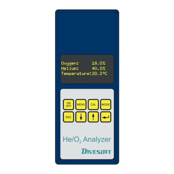
Description of the analyzer 3. Description of the analyzer The analyzer is manufactured from high-strength aluminum alloy, which guarantees stable dimensions and resistance against mechanical damage. The surface is hard-anodized to protect it against scratching. On the front side, the analyzer features a membrane keypad and an OLED display on which the measured values are shown. -
Page 9: Operating The Analyzer
Operating the analyzer 4. Operating the analyzer The analyzer is operated using the keys on its front panel. It is activated by pressing the ON/OFF key for approximately MENU MODE one second. Upon activation, an automatic check of the instrument is performed and the analyzer auto- matically switches to the measuring mode. -
Page 10: Measuring O 2 And He Concentration
Measuring O2 and He concentration 5. Measuring O and He concentration The flow limiter with nozzle is used in the basic configuration (see illustration). Attach the sampler to the compressed gas bottle and use the hose to connect it to the analyzer. -
Page 11: Display Modes
Display modes 6. Display modes Upon activation, the analyzer is normally in the O2/He measuring mode, in one of the two display formats. The basic format shows the oxygen and helium content in the mixture in percent in separate lines and, for information, also the temperature at which the gas was measured. After the measuring begins, the helium concentration may appear in square brackets for several seconds in the basic format. - Page 12 Display modes Warning: The maximum operating depth (MOD) calculated for an actual dive is usually lower than the depth indicated by the analyzer. END is the depth at which the narcotic effect of the mix on the diver is identical to that of air.
-
Page 13: Calibration Of The Oxygen Sensor
Display modes 6.1 Calibration of the oxygen sensor The oxygen sensor’s properties change over time and it is therefore necessary to recalibrate it. We recommend that such calibration be performed at least once a month. Analyzer with the older version than 2.4, the calibration is always necessary when changing altitude. Version 2.4 has a built-in barometer sensor, which corrects itself. -
Page 14: Other Functions
Other functions 7. Other functions 7.1 Continuous analysis The Menu/Continual Analysis option activates the function of continuous-filling monitoring. This mode makes it possible to set up the upper and lower limit of oxygen and helium content. The analyzer continuously measures the concentration of these components and if the preset limits are exceeded, it makes a beeping sound. - Page 15 Other functions Example There is remaining air with the pressure of 120 bars in the twin bottles with the volume of 2 x 12 liters (total volume of 24 liters). The required mix is trimix 18/40 with the required pres- sure of 200 bars.
-
Page 16: Gas Mixing Simulation
Other functions the bottle to the maximum possible extent; therefore, it does not let it discharge completely. Instead, only the necessary part of the mix is discharged. 7.3 Gas mixing simulation Option Menu/Gas mix simulator is for Gas mix simulator function. Simulator will compute mixture content mixed up to from four gases. -
Page 17: Special Accessories
The regulator is constructed from the Divesoft M12 modular system. The illustration shows only one of the possible configurations. Because the leads of the distribution block are equivalent, it is possible to freely reconfigure individual elements according to the user’s ne-... -
Page 18: Pressure Measuring
Special accessories 8.2 Pressure measuring A pressure sensor can be connected to the analyzer. The pressure sensor is generally attached to the connector with the regulator described in the preceding chapter (instead of the plug), so that it is possible to cut off the gas output and measure only the pressure. Of course, it is possible to simultaneously measure the pressure and the gas composition. - Page 19 Special accessories using the partial pressures method and its precision depends on the blender’s experience and estimation. If we know the current gas pressure, tank temperature, gas composition and ambient temperature, we can predict the extent of this decrease on the base of a calculation according to the state equation.
-
Page 20: Voltage Measuring
Special accessories Discharge valve Connector Flow regulator DIN G 5/8 Cut-off valve Tank pressure sensor Tank temperature sensor 8.4 Voltage measuring Optional measuring cables can be attached to the analyzer to measure electric voltage. After the “V” connector is plugged in, the analyzer automatically switches to the mode of a simple low-voltage voltmeter. -
Page 21: Resistance Measuring
Special accessories Warning: If the voltmeter is exposed to the mains voltage, the analyzer will be destroyed and/or personal injury or death due to electric shock may occur! 8.5 Resistance measuring Optional measuring cables can be attached to the analyzer to measure electrical resistance. After the connector “Ω”... - Page 22 Special accessories Preset delay and limiting values you can change after pressing button MENU. Recommended cable wiring: relay 1 for alerting and relay 2 for disconnection of filling station. Maximum relay contacts load is 24V / 500mA. Realy must not be in any case used directly for shut down of compressor, but only for controll circuit (e.
-
Page 23: Set-Up
Set-up 9. Set-up 9.1 Preferences It is possible to change select properties of the analyzer in the basic mode (measuring of He/O in Menu/Preferences. Individual parameters have the following significance: Brightness of the display in the scale of 1 to 127. The selection of low brightness (1) preserves the battery;... -
Page 24: Mixing Of Gases
Set-up 9.3 Mixing of gases The Menu/Gas properties setting is available in the gas-mixing calculation and simulation modes. Individual parameters have the following significance: The State equation option is chosen if the mixing calculations will work with the ideal gas (the status equation PV=RT is used) or with the real gas (state equation according to Redlich and Kwong). -
Page 25: Charging And Battery Status
Charging and battery status 10. Charging and battery status At any time when the analyzer is turned on, you can check the battery status by pressing The value of the battery charge expresses double line at the bottom of display. Range is defined between 0 to 100% charging. -
Page 26: Maintenance
Maintenance 11. Maintenance 11.1 Battery replacement The instrument uses a 9V alkaline battery of the 6F22 type. The battery is placed under the cover on the bottom side of the analyzer. Use only alkaline batteries when replacing. A no. 1 Philips screwdriver is suitable to remove the cover. -
Page 27: Flow Adjusting
Maintenance Warning: The cover is connected to the instrument by several cables. When replacing the sensor, take care not to put excessive tension on the cables or disconnect them. During the replacement, the cables must remain bent by their own weight and flexibility;... -
Page 28: Disassembly Of The Instrument
Maintenance Adjusting of limiting nozzle Connect sampler to the tank, open the valve and set the gas-flowing at the desired value with 2 mm socket-screw key. Setting range is relatively small, maximally ¼ rev. Do not more loosen the setting screw, it can be released and blow out by the gas pressure Correct flow in the right adjusted sampler is 0.2 liter/min. -
Page 29: Connecting To A Computer
Connecting to a computer 12. Connecting to a computer The analyzer can be connected to a computer using a USB cable. Measured values are transferred to the PC via a virtual serial port. If you have not installed a suitable driver for the virtual serial port on the USB, use the free driver provided by the manufacturer of the USB chip used in the analyzer. -
Page 30: Defects And Removal Thereof
Defects and removal thereof 13. Defects and removal thereof Upon activation, the analyzer is automatically tested to identify one of the following errors. All the error messages can be confirmed by the key and the instrument will continue to work; however in some circumstances in a limited operation mode. The overvoltage message (see below) is an exception, as it may be displayed at any time. -
Page 31: Instrument Malfunctions
Defects and removal thereof Error 5 Device is too warm • The temperature of the analyzer is too high (for instance, if it was exposed to sunlight or stored in a car heated by sunlight); the measurement may be inaccurate. Cool down the analyzer below 40 degrees Celsius (104°F). Warning Battery low • The battery is almost empty, it has to be replaced or use the external power source. Error 6 External power overvoltage • The allowed voltage of the external power source was exceeded. This may be caused by mains excessive voltage or by the use of an inappropriate or faulty adapter. -
Page 32: Technical Data
Technical data 14. Technical data Dimensions of the analyzer: 82 x 200 x 37 mm (3 1/4 x 7 7/8 x 1 1/2 inches) Weight: 720 g (1.6 lb) Range of measuring the concentration of oxygen: 0 to 100 % Range of measuring the concentration of helium: 0 to 100 % Measuring temperature: 0 to +40°... -
Page 33: Appendix
Appendix Appendix RL1C relay 1, common, max. 24 V / 500 mA = RL2C relay 2, common, max. 24 V / 500 mA = RL3C relay 3, common, max. 24 V / 500 mA = serial output, TTL level attachment code attachment code attachment code attachment code...
Need help?
Do you have a question about the He/O2 Analyzer and is the answer not in the manual?
Questions and answers