Table of Contents
Advertisement
Advertisement
Table of Contents

Related Manuals for Centralite 3157100


Summary of Contents for Centralite 3157100
- Page 2 Once all wires are removed from the existing thermostat wiring terminal, remove the existing thermostat from the wall. Make sure to leave at least 3” of wire for each connection onto the CentraLite thermostat wiring terminal. Remove 1/8” insulation from the end of each wire.
- Page 3 See Figure-1 “Full Terminal View” P a g e...
- Page 4 RC and RH. (See Figure-1) The CentraLite thermostat can be powered by 4 AA batteries or by the power from the 24V off the HVAC unit if a Common wire is available. Even if you use the common wire for power you should still install 4 AA batteries as a backup for the thermostat time clock.
- Page 5 Figure-1 – Full Terminal View From the factory the thermostat comes configured to work with single stage Cool/Heat, Single Speed Fan systems. If your HVAC system is different refer to the programming section to configure the thermostat for your system. ...
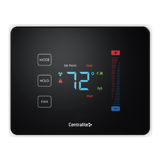
- Page 6 Figure-2 “Thermostat Overview” After completing any necessary configuration make sure the thermostat is in Cool mode by pressing the MODE button until Cool is displayed at the bottom of the screen. (See Figure-3) Make sure the system is not calling for Cooling by setting the setpoint several degrees above the room temperature.
- Page 7 The CentraLite thermostat is intended to operate as part of a ZigBee HA network. The first step in the join process is to make sure the ZigBee HA controller is in a “Join Network Mode”...
- Page 8 If the indicator does not illuminate then make sure the ZigBee HA system controller is “Open” for joining. If the thermostat is part of a network and wish to leave that network and join to a different network, then you will go to the Menu and choose the option to leave network (See Appendix-A for menu options) followed by the join network (Appendix-A).
-
Page 9: Quick Start Guide
Quick Start Guide Technical Support & Installation Programming Mode Menu Functions A thermostat which shows “E0” is a thermostat which has not yet been connected to a “valid” system or one which has not yet been “programmed.” This E0 is the factory default state the thermostat was shipped in and can be removed to a valid status by either programming the thermostat or by hooking up the thermostat to a valid system How to enter thermostat Programming Mode:... - Page 10 Set Maximum Heatpoint ....................6 (Default) – 86 Fahrenheit, 30 Celsius Set Minimum Coolpoint ....................7 (Default) – 44 Fahrenheit, 7 Celsius Set Maximum Coolpoint ....................8 (Default) – 86 Fahrenheit, 30 Celsius Set Minimum Deadband ....................9 (Default) – 1.8 Fahrenheit, 1.0 Celsius Sequence of Operation ....................
- Page 11 Factory Reset All ......................17 11- Yes All others - No Display Configuration and Network Settings ..............18 Order of Display: 1- PSOC Version Number 2- Ember Version Number 3- Heat Type 4- Heat Source 5- Temperature Calibration 6- Relays Detected 7- Network State 8- Network Channel 9-10- PanID...
Need help?
Do you have a question about the 3157100 and is the answer not in the manual?
Questions and answers