Table of Contents
Advertisement
Advertisement
Table of Contents

Subscribe to Our Youtube Channel
Related Manuals for sebaKMT Easyflex Com


Summary of Contents for sebaKMT Easyflex Com
- Page 1 Instruction Manual Easyflex Com Mess- und Ortungstechnik Measuring and Locating Techniques Elektrizitätsnetze Power Networks Kommunikationsnetze Communication Networks Rohrleitungsnetze Water Networks Leitungsortung Line Location Date of release: 2003/34...
- Page 2 MAN_Easyflex_com_eng_01.doc...
- Page 3 Easyflex Com compact and light-weight Time-Domain Reflectometer MAN_Easyflex_com_eng_01.doc...
- Page 4 MAN_Easyflex_com_eng_01.doc...
-
Page 5: Table Of Contents
TABLE OF CONTENTS 1 GENERAL ..................9 1.1 Advice from Hagenuk KMT GmbH ............9 1.2 Terms and conditions of warranty ............10 1.3 Safety Instructions ................11 1.4 Indications used in the description ............12 2 TECHNICAL DESCRIPTION............13 2.1 General Description................ - Page 6 4.1.3 General Instructions on How to Handle a NiMH Accumulator ..46 4.2 Operation ....................47 4.2.1 Safety Precautions................47 4.2.2 Modes of Operation ................47 4.2.3 Practical Hints ..................48 4.3 Troubleshooting ..................49 5 CARE UND MAINTENANCE............49 6 APPENDIX ...................
- Page 7 D-01471 Radeburg Germany declare under sole responsibility that our product Easyflex Com is in conformity with the directive of the Council of European Communities for the Harmonization of the Laws of Member States on Electromagnetic Compatibility (EMC Directive 89/336/EEC) and Low Voltage (Directive 73/23/EEC).
- Page 8 MAN_Easyflex_com_eng_01.doc...
-
Page 9: General
GENERAL Advice from sebaKMT This user manual has been conceived as a reference work. It is intended to help you answer questions and solve problems as quickly as possible. Should you have any problems, please first read the user manual with care. -
Page 10: Terms And Conditions Of Warranty
Terms and conditions of warranty Hagenuk KMT Kabelmesstechnik GmbH will accept a warranty claim brought forward by a customer for a product sold by Hagenuk KMT under the terms stated below and the General Terms of Supply of Products and Services of the Electrotechnical Industries, date of issue May 1993. -
Page 11: Safety Instructions
Therefore, please comply with the following safety instructions! GENERAL INSTRUCTIONS Work on the Easyflex Com and its peripherals must only be carried out by trained and/or instructed staff. Other persons must be kept away. This manual must be available for the supervisory, operating and maintenance staff to refer to. -
Page 12: Indications Used In The Description
The user is under an obligation to report any changes in the Easyflex Com to the supervisor responsible without delay. The operator is under an obligation to shut the Easyflex Com down immediately in the event of a malfunction which detracts from the safety of staff. -
Page 13: Technical Description
TECHNICAL DESCRIPTION General Description is a compact, light-weight and easy-to-handle digital Easyflex Com time-domain reflectometer locating faults balanced telecommunication and control lines. It can be handled easily and so enables even an inexperienced user to locate faults precisely and fast. - Page 14 L1 and Easyflex Com L2 at the same time and to show two reflectograms simultaneously. This can be done using currently taken reflectograms or test results stored in memory.
-
Page 15: Specifications
Specifications Modes of testing: Reflection test of cable connected to socket versus built-in balancing network Reflection test of cable connected to socket versus built-in balancing network Alt: A reflection test is carried out alternately on cables connected to sockets L1 / L2 Diff: Measurement difference... - Page 16 Maximum resolution 1.25 cm for range 50 m at 50 m/µs 2.5 cm for range 50 m at 100 m/µs 2.5 cm for range 100 m 5 cm for range 200 m 10 cm for range 400 m 25 cm for range 1000 m 50 cm for range 2000 m for range 4000 m 2.5 m...
- Page 17 Pulse width Pulse width is linked to range of measurement: 5 ns for range 50 m (100 m/µs) 5 ns for range 100 m 10 ns for range 200 m 20 ns for range 400 m 50 ns for range 1 km 200 ns for range 2 km 200 ns for range 4 km 750 ns for range 7,5 km...
- Page 18 Environmental conditions Operating temperature -10 ° C … +50 ° C Storage temperature -20 ° C … +60 ° C (without accum ulator) Storage temperature -20 ° C … +50 ° C (accumulator) Dimensions, mm 176 x 260 x 70 (L x W x H) 186 x 260 x 70 incl.
-
Page 19: Items Supplied And Optional Extras
Easyflex Com, consisting of Easyflex Com (G,E, two languages on request) - 2 pcs. set of test leads - Case for Easyflex Com - Accumulator 7,2 V / 1,7 Ah / NiMH - Charge case - Plug-in mains unit, for charger case;... - Page 20 Optional Extras: Description for use as Rechargeable accumulator replaceable 7,2 V / 1,7 Ah / NiMH accumulator (Energy DC17AA) Winkis Com PC software for evaluating and storing reflectograms Printer set means for the on-site preparation of test reports Transportation case for printer set Plug-in mains unit external source of...
-
Page 21: Operation
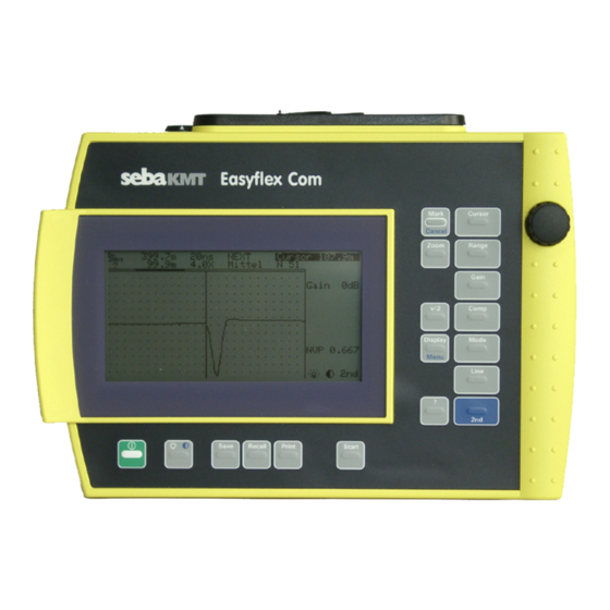
OPERATION Fig 1 , Front View Easyflex Com Measuring Terminals In general, these measuring sockets are used for connecting the faulty line or line to be tested. When using this configuration please make sure that your is set to mode L1. In mode NEXT Easyflex Com this pair of sockets is used for receiving the crosstalk. -
Page 22: Display
Display The LC-Display has 256 x 128 pixels, controls for setting contrast, and switchable back lighting. This enables graphic information to be readable even in difficult lighting conditions. The activated function is display in inverted representation. accumulator condition distance from begin or printing is under way ∆... - Page 23 Use the cursor when you want to change the position of the section and change the X zoom factor when you want to change the width of the section. Fig 3: Reflection by the 2 m Interconnect Cable The LC display will display a warning signal top left when the remaining charge of the accumulator is insufficient for further operation.
-
Page 24: Functions Of Keys And Rotary Encoder
Alt to memories 1 and 2. When you press the help key (?) the will display informations Easyflex Com on one of the following topics : (key ?; select with rotary encoder; press key Mark, key ? for return): •... - Page 25 Marker: Activate cursor; move cursor to start point of Cursor measurement; set marker Cancel Range(Measuring Range) X-Zoom Gain, dB Compensation Propagation velocity / Modes: Single Continuous Single or Dual Display Average Menu Mode of connection: Menu/Units L1, L2, ALT (alternating) Menu/Interface Diff (Difference L1-L2) Menu/Printer...
- Page 26 Possible settings in Menu: Menu/Units Units meter feet seconds NVP units Menu/Interface Baud rate 1200 9600 19200 Parity None (Parity bit) Even Menu/Printer Printer HP Deskjet Epson compatib. Epson 9 pin Kodak Diconix Layout Normal Special Menu/System Self test Software version Serial number Date &...
-
Page 27: Getting Started (Insert / Replace Accumulator)
Getting Started (Insert / Replace Accumulator) The accumulator compartment is located in the back of the Easyflex Com Make sure that all test leads have been disconnected before opening the accumulator compartment. Switch the device off in order to retain all data. -
Page 28: Main Menu
Main Menu Main Menu will appear automatically after the has been Easyflex Com switched on. In this menu measurements are taken employing the device settings that were in effect when the device was used last time. Most functions of can be started directly from menu Measurement Easyflex Com by means of the keys or rotary encoder as described in section 3.3. -
Page 29: How To Locate A Fault
(3) The is able to measure the length of the cable and the Easyflex Com distance to a point of fault. It is not able, however, to find out the route of the cable between the point of measurement and the location of the fault. -
Page 30: Fields Of Application
3.8.1 Fields of Application allows various type of faults to be detected. These are a Easyflex Com few examples: 3.8.1.1 Faults Causing a Negative Reflection (1) Short circuit: Direct contact of two conductors of a cable. This will cause a negative reflection, see Fig 4. -
Page 31: 3.8.1.2 Faults Causing A Positive Reflection
3.8.1.2 Faults Causing a Positive Reflection (1) Open circuit: Open circuit means that one or both conductors of a pair of conductors are broken or have become detached. This will cause a positive reflection, see Fig 5. Fig 5 Type of Fault Causing a Positive Reflection (2) Resistance faults: If a cable is not properly connected in a junction box, increased contact resistance will occur. -
Page 32: 3.8.1.3 Further Fields Of Application
The will interpret the coils used for the Easyflex Com inductive loading of the system as open ends. Connect the instrument to some point behind the coil if you want to locate a fault which is situated beyond the bounds of a coil-loaded section. -
Page 33: Testing A Cable With Known Nominal Velocity Of Propagation Nvp Or
≤ 250 V AC/DC. (2) Use the test leads supplied with the to connect the Easyflex Com Faulty pair to Line 1 and, when appropriate, the good pair to Line 2. (3) Press key to switch the on. - Page 34 Units. The reflectogram can be saved in a the memory for documentation purposes . (11) Press to switch the off after the test has been Easyflex Com completed. MAN_Easyflex_com_eng_01.doc...
-
Page 35: How To Determine An Unknown Nominal Velocity Of Propagation Or Pulse Propagation Velocity
3.8.3 How to Determine an Unknown Nominal Velocity of Propagation or Pulse Propagation Velocity When the nominal velocity of propagation or pulse propagation velocity of the faulty cable is not known, a test sample of the same type of cable with known length is needed (or the distance to a specific point in the cable must be known). -
Page 36: Averaging
In order to solve this problem, the is equipped with Easyflex Com an averaging mode. Press function key Mode and use the rotary encoder to enable mode Averaging. The display will display the number of measurements taken for averaging (max. -
Page 37: Mode Next
Easyflex Com subsequently be eliminated to the point. For instance, the device can determine the beginning and the end of a ”split pairs” section in a longer trunk line which is composed of a number of sections. -
Page 38: How To Use The Marker
If you use only the cursor you can just determine the distance from the to the point of reflection in the cable. The marker offers you Easyflex Com additional means to set a point of reference in the cable and to take measurements in relation to this point by means of the cursor. -
Page 39: Change Of Pulse Width
3.8.8 Change of Pulse Width Press keys 2nd Range to change pulse width. Doing so will not change the display range. Display range Default pulse width Setting range (Range/Zoom at =100 m/µs) 5 ns 5 ns 10 m 5 ns 5, 10 ns 20 m 5 ns... -
Page 40: Self Test
Self Test After turn on, the performs an automatic selftest. If error code Easyflex Com 1 is display the Lithium accumulator is (almost) discharged (the device will still operate for a short while, but you should submit it to the Customer Service to have the Lithium accumulator replaced). -
Page 41: Memory Function
Memory Function has 16 memory locations. This is how to save a trace: Easyflex Com • Press key Save • Use the rotary encoder to select a free memory location or a location that will be overwritten. The selected memory location is displayed in inverted mode •... - Page 42 Mode of Mode of display Indication loading Loading Reflectogram stored in selected memory location A loading The reflectogram from memory is shown as a ,M top right in dotted line, the reflectogram currently taken is front of Cursor shown as a continuous line. If you wish to erase the display of the trace stored in memory, do so by using the key combination Recall...
-
Page 43: Serial Interface
Serial Interface The serial interface of the allows reflectograms to be loaded Easyflex Com to an external PC or to connect a printer for printing out a hardcopy. Go to Menu/Printer to choose from HP Deskjet, Epson combatib., Epson 9 pin, and Kodak Diconix. -
Page 44: Nimh Accumulator Charger
NIMH ACCUMULATOR CHARGER Technical Description 4.1.1 Specification Plug-in mains unit (Euro, USA, UK): Input voltage EURO 230 VAC , ±10 %, 50 Hz 120 VAC , ±10 %, 60 Hz 230 VAC , ±10 %, 50 Hz Power consumption EURO and UK 13.8 VA 14.5 VA Output voltage... -
Page 45: Start-Up
4.1.2 Start-Up First connect the cable from the plug-in mains unit to the DC-IN 12 V socket of the charger, and only then plug the mains unit into a mains outlet (see Fig 13). The green LED of the charger case should now be on continuously, while the amber LED should flash up at regular intervals. -
Page 46: General Instructions On How To Handle A Nimh Accumulator
The accumulator can also be charged from the on-board network of a vehicle. To do this, use the vehicle adapter cable to connect the charger case to the 12 V DC on-board network. Motorcar adapter cable 12 V s upply D C -IN 12 V C harger cas e Fig 13... -
Page 47: Operation
Operation 4.2.1 Safety Precautions Protect the device from moisture. Do not cover the ventilation slots of the plug-in mains unit. Do not insert any items into the ventilation slots. Never expose to direct heat or direct sunlight. Do not open the device as there are no user-maintained components inside and any warranty might be invalidated. -
Page 48: Practical Hints
The optimum way of operation is to have two accumulators, with one remaining in the charger while the other one is used for powering the Easyflex Com The charger and the inserted accumulator will heat up during charging (hand hot). This is normal and does not indicate any defect. -
Page 49: Troubleshooting
Hagenuk KMT hotline. CARE UND MAINTENANCE Neither the nor any of its accessories contain components Easyflex Com which require regular care and maintenance to keep them operational. Submit the or its accessories to your service shop or to Easyflex Com Hagenuk KMT for repair should any defect occur. -
Page 50: Appendix
APPENDIX List of Abbreviations Used Alternating test Direct current Electromagnetic compatibility International Electrotechnical Committee Liquid crystal display Light emitting diode NEXT Near end cross (X)-talk NiMH Nickel metal hydrid Nominal velocity of propagation Time domain reflectometer Verein Deutscher Elektrotechniker (Association of German Electrotechnical Engineers) MAN_Easyflex_com_eng_01.doc... -
Page 51: Conversion: Nvp
Conversion: NVP ⇔ ⇔ ⇔ ⇔ Conversion NVP µs • 299.79 µ Conversion µs • 2 299.79 µ MAN_Easyflex_com_eng_01.doc... -
Page 52: For Common Types Of Cables
Table: NVP and for Common Types of Cables Typical propagation time , ft/µs Insulation m/µs Oil- 75-84 246-276 0.50- impregnated 0.56 paper Poly, cross- 78-87 256-285 0.52- linked 0.58 Poly, filled with 96.0 314.8 0.64 Petrolat Polyethylene 100.5 329.6 0.67 PTFE 106.5 349.3... - Page 53 From your own measurements: Propagation time , m/µs , ft/µs Insulation or type of cable MAN_Easyflex_com_eng_01.doc...
-
Page 54: Glossary
It is used for suppressing the display of the transmitter pulse so that reflections can be depicted and measured directly from the output of the Easyflex Com – there is no dead zone as otherwise usual. MAN_Easyflex_com_eng_01.doc... - Page 55 (e.g. a faulty junction box with improper shielding of individual pairs from one another). The Easyflex Com is able to locate these types of faults. (= Nominal Velocity of Propagation) The value of NVP, also called propagation time factor or ”reduction factor”...
- Page 56 (twisted pairs) to avoid any interference effects. (= Time Domain Reflectometer) The Easyflex Com is a reflectometer operating in what is known as the time domain. Apart from the amplitude, the Easyflex Com measures exclusively propagation times with...
- Page 57 In cable testing it is common practice to specify the signal propagation velocity in term of half the actual velocity. When employing the reflection technique, this is a usual way of taking twice the signal travel path into account. To depict a reflection on the screen, the signal has to travel from the meter to the fault and back.
Need help?
Do you have a question about the Easyflex Com and is the answer not in the manual?
Questions and answers