Miranda Kaleido-X16 User Manual
Hide thumbs
Also See for Kaleido-X16:
- Hardware description and installation manual (82 pages) ,
- Hardware description & installation manual (45 pages) ,
- Quick start manual (33 pages)
Table of Contents
Advertisement
Quick Links
Advertisement
Table of Contents

Related Manuals for Miranda Kaleido-X16


Summary of Contents for Miranda Kaleido-X16
- Page 1 User’s Manual M770-2800-120 10 July 2013...
- Page 2 Miranda. A Miranda manual may have been revised to reflect changes made to the product during its manufacturing life. Thus, different versions of a manual may exist for any given product.
-
Page 3: Table Of Contents
Kaleido-X16 ........ -
Page 4: Table Of Contents
Table of Contents Triggering Actions............54 Triggering GPI Output Events . -
Page 5: Table Of Contents
Kaleido-X User’s Manual Detailed Directions ............. 140 Configuring Alarm Thresholds . -
Page 6: Table Of Contents
Table of Contents Creating Monitor Wall Actions ..........269 Creating Background Actions . -
Page 7: Table Of Contents
Enabling Options............411 Configuring Power Supply Redundancy on a Kaleido-X16....413 Installing XEdit . -
Page 9: New Features
New Features This chapter describes new features in Kaleido-X version 7.00. New Features and Enhancements in Kaleido-X Version 7.00 Kaleido-X version 7.00 is a major release, introducing support for the Kaleido-MX and Kaleido-Modular-X multiviewer models, and is available for these new multiviewer models only. - Page 10 a GPI to Ethernet interface between a multiviewer and other devices. The multiviewer publishes GPI and card status information to the multiviewer’s GSM. • Loudness/dialnorm calibrations: The range of the Max. lower deviation [Ref. #KX-6477] parameter has been extended down to -64 dB, which allows you to configure your system so that the Loudness/Expected alarm is not triggered when silence is detected.
-
Page 11: Getting Started
(e.g. welcome letters, warranty cards) are distributed in printed form. All manuals are available on the Kaleido-X DVD. You can obtain the latest version of the manuals, the Release Notes, as well as software and useful data, from the Software and documentation section of Miranda’s support portal. -
Page 12: System Overview
• For the Kaleido-IP X300 and Kaleido-IP X100, see Kaleido-IP, on page 5. • For the KMV-3901, and KMV-3911, see Kaleido-Modular KMV-3901/3911, on page 5. • For the Kaleido-X16 (single head) and Kaleido-X16 (dual head), see Kaleido-X16, on page 6. • For the Kaleido-X, see •... -
Page 13: Kaleido-Ip
Kaleido-X User’s Manual Kaleido-IP The Kaleido-IP can monitor and display HD and SD television programs distributed over IP, across two HDTV displays. It supports MPEG-2 and H.264/AVC compressed video, and the AAC, AC-3, MPEG-1, MPEG-2, MPEG-4 AAC LC, and MPEG-4 HE-AAC compressed audio formats, within unencrypted DCII, DVB, or ATSC streams. -
Page 14: Kaleido-X16
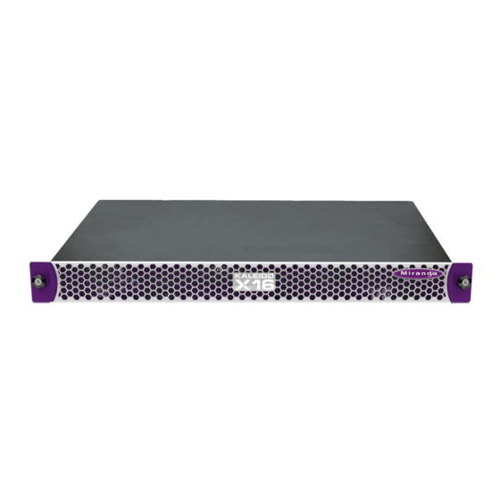
• Super silent for installation within studios and control rooms Kaleido-X16 The Kaleido-X16 is a compact, ultra-quiet multiviewer with 16 inputs, and one or two HDMI outputs. It offers the highest level of image quality, and can be used with 3Gbps/HD/SD and Analog video. - Page 15 User’s Manual Kaleido-X16-D system overview The 1RU Kaleido-X16 is ideal for smaller monitoring facilities, such as call letter television station master control rooms, mobile trucks and production fly cases, as well as community television. The Kaleido-X16’s super silent design is highly appreciated for use within studios and control rooms.
-
Page 16: Kaleido-X (4Ru)
Getting Started Kaleido-X (4RU) • DXF-100 optical DVI extension module simplifies long runs to monitors from frame, and is a single fiber solution for supporting high-resolution (1920 × 1200) displays over distances of up to 1000 m (3280 ft) • Choice of multiviewer remote control panels: simple Kaleido-RCP2 and advanced RCP- 200 with router control •... -
Page 17: Kaleido-X (14Ru) Expansion
Kaleido-X (7RU) system overview Kaleido-X (14RU) Expansion Since version 3.00 of Miranda’s Kaleido-X software, it is possible to expand the input connectivity of one Kaleido-X (7RU) frame to include that of a second. The two frames, each with its own expansion (KXO-EXP) card, are connected by a high bandwidth cable, such that all the output (KXO) modules on each frame (up to 6 in total) have access to all inputs (KXI) on each frame (up to 192 in total) without any blocking or bandwidth limitations. -
Page 18: Cluster
Getting Started Cluster Kaleido-X (14RU) expansion system overview Cluster As of version 4.00 of the Kaleido-X software, it is possible to configure a cluster system, allowing operation of layouts sharing output signals from multiple multiviewers fed by a router, while using only one mouse, and one Kaleido-RCP2 or RCP-200. Refer to Creating a Cluster, on page 81, for more information. -
Page 19: Cascade
Cluster system overview Cascade It is possible to configure up to three Kaleido-X16 or KMV-3901/3911 multiviewers as a cascade system. Unlike the cluster, whose purpose is to increase the number of output heads in a room, the cascade increases the maximum number of inputs that can be displayed to a single monitor wall display. - Page 20 Getting Started Verifying your System Configuration The Kaleido-X home page appears. Firefox users: If you see a security warning instead of the home page, then refer to Registering your Multiviewer's Security Credentials with your Browser, on page 421. 2 Click the XAdmin button. XAdmin’s Status and Options page appears, displaying a list of all modules and their statuses.
- Page 21 Kaleido-X User’s Manual Internet Explorer users: • If the page remains blank, then refer to Enabling the Compatibility View in Internet Explorer 10, on page 429. • If you see a certificate error message instead of the Status and Options page, then refer to Registering your Multiviewer's Security Credentials with your...
- Page 22 Web browser. • In the case of a Kaleido-X16 or Kaleido-Modular multiviewer model, click the “Reset multiviewer” button at the end of the multiviewer’s heading row to reset the multiviewer remotely, directly from your Web browser.
- Page 23 Kaleido-X User’s Manual Note: In the case of a Kaleido-IP multiviewer, there are currently no options that can be enabled via XAdmin. See Hardware and Software Options page 383 for more information on the options available for the different multiviewer models. 6 If your system supports a GPI interface, you can check the main system statuses of the multiviewer, to make sure that there are no errors or alerts related to system temperature, power supply status, fan operation, or other card fault conditions.
- Page 24 The KXA-GPI-GEN card, with support for GPI, is standard on the Kaleido-X (7RU), and optional for the Kaleido-X (4RU). GPI support is built-in on the Kaleido-X16, and Kaleido-Modular multiviewers. Not available on the Kaleido-IP. If you have a Kaleido-X (4RU) without a KXA-GPI-GEN card, then you will find the fan and power supply statuses listed with the master output card’s information.
- Page 25 Kaleido-X User’s Manual In the case of a Kaleido-X16 or Kaleido-Modular multiviewer, the relevant indicators are found under the SYSTEM module. Verifying a Kaleido-RCP2 To verify that the Kaleido-RCP2 is functioning normally 1 Log on to the appropriate room the Kaleido-RCP2 (see...
-
Page 26: Loading A Layout
Getting Started Loading a Layout Color Board Status Orange Activity Hardware fault Flashing red Upgrading firmware Two LEDs are visible on the front panel, one for each power supply. When lit, they both indicate the same status: Color Board Status Green Normal Flashing green... - Page 27 (in the case of the Kaleido-X multiviewer models) or all video streams connected to the multiviewer’s inputs (in the case of a Kaleido-X16 or Kaleido-Modular multiviewer model). 3 Choose a default layout from the layout browser.
-
Page 28: Cabling Diagrams
Getting Started Cabling Diagrams Cabling Diagrams Kaleido-IP Cabling diagram for a Kaleido-IP X100 or X300 with two network adapters. The Kaleido-IP X300 model may have two, or four additional DATA ports (LAN3 – LAN6). KMV-3901/3911 Cabling diagram showing KMV-3911 rear panel. - Page 29 Kaleido-X User’s Manual Kaleido-X16 Kaleido-X (4RU)
-
Page 30: Rs-422 Connection Diagram
KMV-3911 Guide to Installation and Operation, available on the DVD that shipped with your system, and from Miranda’s support portal. In the case of a Kaleido-X multiviewer, each output card supports one RS-422 port over an RJ-45 connector. The Kaleido-X16 supports two RS-422 serial inputs over RJ-45 connectors. - Page 31 (part no. 1737-3000-102), and a crossover adapter (part no. 1792-3700-100). The pinout for the RS-422 signals at the RJ-45 connectors on a Kaleido-X16—or on the output cards’ rear panel, in the case of a Kaleido-X—, and the wiring diagrams for the...
-
Page 32: Xedit Application Shortcuts
XEdit Application Shortcuts The following is a list of shortcut keys available in XEdit to execute specific actions. Action Shortcut key Save Ctrl+S Import sources from spreadsheet Ctrl+I Toggle the status bar Ctrl+Shift+B Toggle the layout navigator Ctrl+Shift+N Toggle the grid Ctrl+Shift+G Toggle the Tools pane Ctrl+Shift+T... -
Page 33: Operation Of The Monitor Wall
Operation of the Monitor Wall This section introduces the Kaleido-X monitor wall features. Key Concepts Monitor wall The monitor wall refers to the group of display screens that are connected to the output modules of a specific Kaleido-X system. Room A room is a visual grouping of display screens. - Page 34 Operation of the Monitor Wall Key Concepts Logical source A logical source (called a channel, in earlier versions of the documentation) refers to a group of physical audio, video, or metadata sources, and text attributes. A logical source can be used as a whole, and assigned to a virtual monitor.
- Page 35 Kaleido-X User’s Manual Subtitling A subtitling monitor defines an area for displaying subtitles extracted from a monitor video signal. By using a subtitling monitor you can monitor subtitling from a specific DVB stream, independently from the associated video stream. Requires the CC/XDS option (see Hardware and Software Options, on page 383).
- Page 36 Crosspoint A multiviewer can control upstream routers, and it can also be controlled as a router itself. In addition, some multiviewer models—Kaleido-X16, Kaleido- X (7RU), and Kaleido-X (14RU)—can have optional router outputs. A crosspoint is the link inside a router between a source (input) and a destination (output).
-
Page 37: Detailed Directions
Output cards A, B and C of each of Frame A and Frame B are assigned to ROOM1, ROOM2, ROOM3, ROOM4, ROOM5 and ROOM6 respectively. • On a Kaleido-X16-D, the HDMI outputs from each of the Output modules are assigned to ROOMX16. - Page 38 For more information on the Kaleido-RCP2, please refer to the Kaleido-RCP2 Guide to Installation and Operation, available on the DVD that shipped with your system, and from Miranda’s support portal. Logging on to the Monitor Wall Using the RCP-200 To log on to a Kaleido-X room from the RCP-200 1 On an RCP-200 with an active connection to the network, press the LIST button.
- Page 39 • Two users accessing the same display will be limited to sharing a single pointer. For more information on the RCP-200, please refer to the RCP-200 Guide to Installation and Operation, available on the DVD that shipped with your system, and from Miranda’s support portal.
-
Page 40: Using On-Screen Wall Control
Operation of the Monitor Wall Using On-Screen Wall Control Using On-Screen Wall Control Locating the Mouse Pointer on the Monitor Wall If you have a cluster system, the monitor wall may comprise a large number of display screens, where the mouse pointer location is not always obvious. To locate the mouse pointer on the monitor wall •... -
Page 41: Hiding The Dashboard
Kaleido-X User’s Manual as needed, to view the Kaleido-X system name, IP address, software version and current error messages. In such cases you must close the dashboard manually. Note: It is possible to disable the automatic display of the dashboard on specific displays. -
Page 42: Loading Layouts
Operation of the Monitor Wall Loading Layouts clicked a layout element), and then click Hide dashboard to hide the dashboard on the current display. Hide dashboard Note: Clicking the × button closes the dashboards on every display monitor in the room if they were displayed automatically. To hide all the dashboards •... - Page 43 Kaleido-X User’s Manual 2 Select the layout you wish to load, from the set of layouts defined for this room, and then click OK. The new layout appears on the monitor wall. Loading a Layout by Using the Kaleido-RCP2 To load a layout on the monitor wall, by using the Kaleido-RCP2 1 Press LOAD on the Kaleido-RCP2.
-
Page 44: Displaying A Source In Full Screen Mode
Operation of the Monitor Wall Displaying a Source in Full Screen Mode Loading a Layout by Using the RCP-200 To load a layout on the monitor wall, by using the RCP-200 1 Touch LAYOUT SELECT on the RCP-200’s right-hand screen. The layout chooser view appears. -
Page 45: Changing A Source's Aspect Ratio
Kaleido-X User’s Manual Changing a Source’s Aspect Ratio To change the aspect ratio using the Kaleido-RCP2 • Move the pointer over the video source whose aspect ratio you wish to change, and then press ASPECT RATIO on the Kaleido-RCP2. Continue pressing ASPECT RATIO to alternate between the available aspect ratio options (4:3, 16:9, and possibly a third custom aspect ratio if one was defined in XEdit for the monitor). - Page 46 Operation of the Monitor Wall Video Cropping/Zooming To toggle the cropping mode using the RCP-200 1 Touch the WALL MOUSE category if it is not already selected, and then move the pointer over the video source whose cropping mode you wish to change on the monitor wall.
-
Page 47: Toggling Safe Area Markers
Kaleido-X User’s Manual Notes (continued) • Safe title area and aspect ratio markers follow the video signal (e.g. if the safe title area is within 5% of top, left, right and bottom, then when the video is in default overscan mode, the safe title area markers will not appear). -
Page 48: Displaying Subtitles And Closed Caption Text
Operation of the Monitor Wall Displaying Subtitles and Closed Caption Text Displaying Subtitles and Closed Caption Text Notes • The KMV-3901/3911 does not support extraction of subtitles and closed captions. • Only the Kaleido-IP supports extraction of DVB subtitles. • The Kaleido-IP supports extraction of CEA-608 and CEA-708 closed captions, in addition to DVB subtitles. - Page 49 Kaleido-X User’s Manual To prevent the menu from being too crowded by CC (608), CC (708), DVB subtitling, and Teletext/subtitling options, its content (label, icon and available choice) changes, depending on the current video format: Signal type Text Mode Indicator Label Available choices SD-SDI/CVBS 525, Auto...
- Page 50 Operation of the Monitor Wall Displaying Subtitles and Closed Caption Text Note: The shortcut menu displays Service 1 to Service 6. Use the Extended services sub-menu to select from the Service 7 to Service 63 range. When an extended service is enabled it is added to the shortcut menu below Service 6.
-
Page 51: Editing Umd Text
Kaleido-X User’s Manual The shortcut menu displays Page A (###) where “###” is the number of the actual page being monitored (from 100 to 899). It is possible to change the assignment using the Edit pages sub-menu. This menu allows you to configure the page selection for the current input. To switch teletext/subtitling off •... -
Page 52: Selecting An Input Method
Operation of the Monitor Wall Selecting an Input Method Selecting an Input Method Note: In the case of a KMV-3901/3911 multiviewer, the current version of the Kaleido-X software does not support input methods on the monitor wall. As a workaround, you can use XEdit, open the layout that contains the text you wish to modify (e.g. - Page 53 Kaleido-X User’s Manual The label of each category/index button in Assign Source is based on recurring strings found in the logical source names available for your system. The Src box shows the current assignment. 2 Click through the categories until the Pst box shows the logical source you wish to assign to the selected monitor.
- Page 54 Operation of the Monitor Wall Assigning Sources to Monitors 2 If you have yet to assign the CHANNEL wall function to one of the programmable knobs, rotate the knob you wish to program until CHANNEL is selected, and then press the knob.
-
Page 55: Changing Crosspoints
Kaleido-X User’s Manual The Assign Source window appears. Current assignment The label of each category/index button in Assign Source is based on recurring strings found in the logical source names available for your system. The Src box shows the current assignment. 3 Click through the categories until the Pst box shows the logical source you wish to assign to the selected monitor. - Page 56 Operation of the Monitor Wall Changing Crosspoints The video from the first video level assignment within the selected logical source appears in the video window. When the current layout is reloaded, either of the following two situations may apply. • No logical source: If there was no logical source associated with the monitor, then the Kaleido-X will remember the new source assignment.
- Page 57 Changing an Internal Router Crosspoint Notes • This feature is only available on Kaleido-X (7RU), Kaleido-X (14RU), and Kaleido-X16 multiviewers, with the SDI Router Output option, and whose internal router is properly configured within the first level of the KX Router logical router See Configuring a Multiviewer’s Internal...
- Page 58 Operation of the Monitor Wall Changing Crosspoints The source signal displayed on the monitor is routed to the selected destination. Changing an External Router Crosspoint Note: As of version 5.20 of the Kaleido-X software, when a multiviewer manages an upstream router, you should manage the router’s physical sources as logical sources within the multiviewer system (see page 157).
-
Page 59: Using Timers
Kaleido-X User’s Manual The multiviewer requests the specified source signal from the router. Note: What you see on the wall is not a list of physical inputs, but of logical inputs (labels). Once you have established your configuration in XEdit, you always work with logical devices/levels. - Page 60 Operation of the Monitor Wall Using Timers Stop Down Overrun Remaining Loop Notes • Timer monitors display time in HH:MM:SS format. Even if the monitor is synchronized with an LTC source, frame count is not displayed. • Using a timer monitor’s Reset, Timer mode or End behavior buttons will stop the timer, if it was running.
- Page 61 Kaleido-X User’s Manual The timer monitor is updated accordingly. 3 Use the Preset controls to set a new preset time. 4 Click the Reset button to reset the timer to its initial value (based on timer mode and preset time). 5 Click the Start button to start the timer.
-
Page 62: Triggering Actions
Operation of the Monitor Wall Triggering Actions To configure your assigned timer, by using a numeric keypad • Press the slash key (“/”) to set the timer mode and end behavior. Keep pressing the key to cycle through all the available options, until the buttons show the appropriate settings. -
Page 63: Acknowledging Alarms
Kaleido-X User’s Manual The GPI line’s state changes. Note: GPI lines configured as outputs can have their state set manually for test purposes in XEdit’s System tab: Acknowledging Alarms Acknowledging Alarms on the Monitor Wall To acknowledge an alarm, by using the Kaleido-RCP2 •... -
Page 64: Triggering Audio Monitoring
Operation of the Monitor Wall Triggering Audio Monitoring Unlatch/Acknowledge all This will acknowledge every alarm monitored in the current room. Acknowledging Alarms by Using an Action To acknowledge alarms, by using an action • Create a Unlatch/Acknowledge all action. This action can be assigned to a monitor on the monitor wall, it can be triggered by loading or unloading a layout, or it can be a background action. - Page 65 Kaleido-X User’s Manual • press AUDIO MONITORING on the Kaleido-RCP2 • press the AUDIO MONITOR programmable knob on the RCP-200 This will route the specific audio level associated with the video monitor, based on the assigned logical source. • Move the pointer over any other monitor, and then •...
-
Page 66: Setting A Display Monitor's Output Resolution
Alternatively, use a keyboard connected to the Kaleido- RCP2. • In the case of a Kaleido-X16, connect the keyboard to one of the USB ports on the multiviewer. If two displays are connected to the multiviewer, then the resolution is applied to both. - Page 67 Kaleido-X system. Setting an output head to a specific resolution, from a multiviewer service panel in iControl (if available), from the monitor wall (Kaleido-IP, Kaleido-X, Kaleido-X16), or from a Densité controller’s local control panel (Kaleido-MX, Kaleido-Modular-X, KMV-3901/3911, Kaleido-XQUAD) disables the EDID auto-detection for this head.
-
Page 68: Changing The Ip Address Of A Multiviewer From The Monitor Wall
In the case of a Kaleido-IP, changing the multiviewer’s network settings from the monitor wall is not yet supported. With a Kaleido-X, or Kaleido-X16, you can set the IP address, system name, and other parameters via a control panel on the monitor wall. -
Page 69: Managing Kaleido-X Systems
The Kaleido-X16 is a compact, ultra-quiet multiviewer in a 1RU frame, with 16 inputs and two outputs. It provides a subset of the features of the Kaleido-X 4RU and 7RU models. There are two types of Kaleido-X16: Kaleido-X16-S (single head) and Kaleido-X16-D (dual head). - Page 70 Managing Kaleido-X Systems Key Concepts Term Description Kaleido-IP The Kaleido-IP can monitor and display HD and SD television programs distributed over IP, across two HDTV displays. It supports MPEG-2 and H.264/AVC compressed video, and the AAC, AC-3, MPEG-1, MPEG-2, MPEG-4 AAC LC, and MPEG-4 HE-AAC compressed audio formats, within unencrypted DCII, DVB, or ATSC streams.
- Page 71 81. Cascade A cascade refers to up to three Kaleido-X16 or up to three KMV-3901/3911 multiviewers, configured so that they can be operated as a single system from a room. The cascade makes it possible to monitor up to 48 video inputs—in the case of a Kaleido-X16 cascade—, or up to 24 video...
- Page 72 Managing Kaleido-X Systems Detailed Directions Term Description In XAdmin the virtual slot/card concept is represented as follows: • Cards in virtual slots have no name. • There is no reset button associated with each card. Instead, there is a single multiviewer reset button that sends a reboot command to the multiviewer.
- Page 73 Kaleido-X User’s Manual 2 When prompted to specify the database location, click Browse. 3 From the window that opens, locate an appropriate directory for your workspace, and then click Open to close the Select the database location window. If it is not the first time you open XEdit, and you are satisfied with the location of your local workspace, then select the Don’t ask next time check box, to avoid being prompted every time you open XEdit.
- Page 74 Managing Kaleido-X Systems Opening the XEdit Software When first opening XEdit in offline mode, the database contains the default configuration for a Kaleido-X (7RU) system, including a fully-populated frame (all cards present) and a set of predefined logical sources. To customize the layout of the XEdit application window •...
-
Page 75: Using Xedit Online
Kaleido-X User’s Manual 2 On the View menu, point to Panes and tabs, and then click Restore default window settings. To close XEdit • On the File menu, click Exit. Alternatively, click the × button in the upper right corner of the main application window. - Page 76 Managing Kaleido-X Systems Using XEdit Online The selected system’s hierarchical list appears in XEdit’s main pane, showing the multiviewer model, system name and IP address, and the status bar shows the connection status. Connection status Multiviewer model System name System IP address It is also possible to verify which version of the Kaleido-X software is installed on this multiviewer, by moving to pointer to the system name in the System list.
- Page 77 Kaleido-X User’s Manual Notes • When using XEdit in online mode, some database functions, such as Export, Import, and Restore backup, are not available. Any changes made by the user are not kept locally on the user’s PC, but applied directly on the multiviewer multiviewer.
-
Page 78: Importing A Database
Managing Kaleido-X Systems Importing a Database Access control is now enabled for this multiviewer. Disabling Access Control To disable access control 1 Connect to the multiviewer you wish to unprotect (see Connecting to a Multiviewer, on page 67). XEdit prompts you for a password. 2 Type the password associated with the RCP user Admin, and then click Log on. - Page 79 Kaleido-X User’s Manual IP addresses for all the multiviewers that are on the same subnet as your PC are included in the list. 2 If your PC and the multiviewer are on the same subnet, then you can select the IP address of the multiviewer from the list.
-
Page 80: Exporting A Database
Managing Kaleido-X Systems Exporting a Database Bold text indicates the cluster member to which XEdit is currently connected. Connection status System name Multiviewer System IP address model Exporting a Database Exporting a Single-Multiviewer Database To export a single-multiviewer database 1 On the Configure menu, point to Database, and then click Export. The Export to Multiviewer window appears, prompting you for the IP address of the multiviewer to which you wish to transfer the database. - Page 81 Kaleido-X User’s Manual 2 If your PC and the multiviewer are on the same subnet, then you can select the IP address of the multiviewer from the list. Otherwise type the appropriate IP address in the box. 3 Click OK. A window appears, prompting you to confirm that you really want to export data to the multiviewer.
- Page 82 Managing Kaleido-X Systems Exporting a Database If you were working in offline mode, against a database imported from your existing cluster system, and all cluster members are currently available, then click OK to proceed. On the other hand, if a cluster member happens to be unavailable, or if you are cloning a cluster configuration to a different set of multiviewers, you may need to remove members from the selection and change IP addresses.
-
Page 83: Creating A Backup
Kaleido-X User’s Manual A progress window appears, followed by a message stating whether the export succeeded or not. 4 Click OK. All cluster members now have the latest configuration from the local workspace. Creating a Backup Use the Create backup and Restore backup functions to manage copies of your system database. -
Page 84: Restoring A Backup
Managing Kaleido-X Systems Restoring a Backup The Create Backup window appears. 2 In Create Backup, select the location where you wish to save a backup copy of the resolutions from the current database, and then click Save. The resolutions are saved as an XEdit collection file, with a extension. -
Page 85: Creating A Single Multiviewer System
Kaleido-X (7RU) system, including a fully-populated frame (all cards present) as a starting point. If you have a different multiviewer model—i.e. a Kaleido-IP, a Kaleido- Modular, a Kaleido-X16, a Kaleido-X (4RU) or an expansion system—, then you must replace this initial configuration with one that matches your actual system. - Page 86 System list is selected. 3 Right-click the current multiviewer in the System list, and then select the appropriate multiviewer model—Kaleido-X16-S, Kaleido-X16-D, Kaleido-X (4RU), Kaleido-X (7RU), Kaleido-X (14RU), Kaleido-Modular, Kaleido-MX, Kaleido-IP-2, Kaleido-IP-4, or Kaleido-IP-6—, from the “replace with... ” options on the menu.
- Page 87 Conversely, if the current model is not a Kaleido-IP, then none of the Kaleido-IP models are available for selection. Select... To represent a... Kaleido-X16-S Kaleido-X16 (single output) Kaleido-X16-D Kaleido-X16 (dual output) Kaleido-X (4RU) Kaleido-X (4RU) Kaleido-X (7RU) Kaleido-X (7RU)
- Page 88 Managing Kaleido-X Systems Creating a Single Multiviewer System 4 Click Yes. The next message prompts you about populating the database with a factory-default configuration for the selected multiviewer model. 5 Click Yes to have the system populated with factory defaults for the selected multiviewer model.
-
Page 89: Creating A Cluster
Kaleido-X User’s Manual Creating a Cluster As of version 6.50 of the Kaleido-X software, clusters can be created and configured in offline mode, in addition to the previously supported online mode. Creating a cluster involves the following steps: 1 add multiviewers to your system 2 configure new rooms that include displays fed by the different multiviewers 3 create layouts for the new rooms 4 replicate RCP users from one multiviewer to all other systems that are part of the cluster... - Page 90 Managing Kaleido-X Systems Creating a Cluster on page 67. You are now ready to add more multiviewers to the system. 2 In the equipment library, select any multiviewer model, and then drag it onto the root of the System hierarchical list. The Add Multiviewer to Cluster window appears.
- Page 91 Creating a Cluster in Offline Mode To create a system with multiple multiviewers in offline mode 1 In the equipment library, select the appropriate multiviewer model—Kaleido-X16-S, Kaleido-X16-D, Kaleido-X (4RU), Kaleido-X (7RU), Kaleido-X (14RU), Kaleido- Modular, Kaleido-MX, Kaleido-IP-2, Kaleido-IP-4,or Kaleido-IP-6—, and drag it onto the root of the System hierarchical list.
- Page 92 Managing Kaleido-X Systems Creating a Cluster 2 A multiviewer of the selected model is added to the System list. 3 On the File menu, click Save. A progress window appears while XEdit applies default settings to your new cluster configuration. 4 Repeat from step 1 until you have added all the required devices to the cluster.
- Page 93 Kaleido-X User’s Manual 5 If further system configuration is required on the individual members of the cluster, start with the current system (i.e. the one that is highlighted). See Configuring the System Representation on page 87, for detailed instructions on adding cards to a Kaleido-X (4RU, 7RU, or 14RU), or on adding streams to a Kaleido-IP configuration.
- Page 94 Managing Kaleido-X Systems Creating a Cluster Creating Rooms for a Cluster System Create rooms for the cluster system, by adding displays associated with the different multiviewers as appropriate. See Setting Up Rooms on page 173, for details. Notes • Each room must have a unique name across the cluster system. XEdit will not let you use a name if there is already a room with this name associated with one of the multiviewers within the cluster.
-
Page 95: Configuring The System Representation
Managing Cards in a Kaleido-X System Representation on page 100, for details. • This section does not apply to the Kaleido-X16, Kaleido-XQUAD, and KMV-3901/3911, which have a set number of virtual card slots that represent hardware features integrated within their main board. In XEdit, these virtual card slots are, for the most... - Page 96 Streams, on page 99. Importing a Stream Lineup WARNING Miranda recommends making a backup of your system before importing stream configuration information from a spreadsheet. When you import streams from a spreadsheet, this erases all previously imported streams and associated logical sources. It may also overwrite streams that you had manually added (and logical sources) if they have the same name or index as a stream whose configuration is being imported.
- Page 97 Kaleido-X User’s Manual Imported streams Example showing streams imported from the sample spreadsheet file. After a few minutes, if XEdit is connected to the multiviewer, all programs included in the transport streams are discovered. Note: The set of discovered programs does not necessarily match the programs listed in the spreadsheet.
- Page 98 Managing Kaleido-X Systems Configuring the System Representation Preparing a Spreadsheet with Stream Lineup Information The spreadsheet file must contain the following: • information about the programs you wish to monitor, and the transport streams to which they belong, • information about the logical sources that will be added to the sources table for these programs, including any static text levels you may wish to add.
- Page 99 Kaleido-X User’s Manual Sample spreadsheet: Programs, and Transport streams areas 3 Enter the information that will be used to create the logical source associated with this program: In this column... Enter this information... Index If your system involves a control panel from which you control your multiviewer as a router, set a source number for the logical source associated with this program to be available through the KX Router logical router, by entering the appropriate number in...
- Page 100 Managing Kaleido-X Systems Configuring the System Representation 4 Optionally, use the columns, starting at column K, to add static text levels. Enter the level name on the second heading row. Sample spreadsheet: Additional static text levels area 5 Repeat this procedure until you have added the required information for all the programs you wish to monitor.
- Page 101 Kaleido-X User’s Manual 3 Drag Multicast from the Tools pane onto the network adapter. The Multicast Stream Configuration window appears. 4 In Multicast Stream Configuration, replace the default stream name if desired, select the appropriate protocol (RTP, UDP), type the multicast group address and port number associated with the transport stream you wish to add.
- Page 102 Managing Kaleido-X Systems Configuring the System Representation Source IP address Group address Port number (or range) Protocol Transport stream Program Elementary stream (audio) Elementary stream (video) Note: Under the network adapter elements, transport streams are listed in alphabetical order. 6 Repeat this procedure until you have added all required SSM/SFM transport streams to your system configuration.
- Page 103 Kaleido-X User’s Manual 3 Drag Multicast from the Tools pane onto the network adapter. The Multicast Stream Configuration window appears. 4 In Multicast Stream Configuration, replace the default stream name if desired, select the appropriate protocol (RTP, UDP), type the multicast group address and port number associated with the transport stream you wish to add, and then click OK.
- Page 104 Managing Kaleido-X Systems Configuring the System Representation Group address Port number (or range) Protocol Transport stream Program Elementary stream (audio) Elementary stream (video) Note: Under the network adapter elements, transport streams are listed in alphabetical order. 5 Repeat this procedure until you have added all required ASM transport streams to your system configuration.
- Page 105 Kaleido-X User’s Manual 3 Drag Unicast from the Tools pane onto the network adapter element. The Unicast Stream Configuration window appears. 4 In Unicast Stream Configuration, replace the default stream name if desired, select the appropriate protocol (RTP, UDP), type the port number associated with the transport stream you wish to add, and then click OK.
- Page 106 Managing Kaleido-X Systems Configuring the System Representation Modifying a Transport Stream To modify the settings for a transport stream 1 In the main window, click the System tab, and then click Description/Calibrations on the second level tab bar. 2 Expand the System hierarchical list, and then navigate to the transport stream you wish to configure.
- Page 107 Kaleido-X User’s Manual Notes • The Kaleido-X software supports UTF-8 encoded stream names. The only characters, which cannot be used in a stream name are: @ / \ ' " • Verify the protocol you selected. Registering an RTP stream as UDP instead of RTP may result in the decoded video appearing jerky or accelerated on the monitor wall.
- Page 108 Managing Kaleido-X Systems Configuring the System Representation 5 When prompted to confirm, click Yes. 6 On the File menu, click Save. Changes to the system are saved. If you are not planning on adding these streams back to your system, then you may now wish to remove logical sources that were based on them: see Removing Logical Sources for Removed Programs in a Transport Stream, on...
- Page 109 Kaleido-X User’s Manual 3 Add or remove cards until the system’s card slots are populated with cards that match the hardware configuration of your multiviewer: see Emptying Card Slots, below, and Populating Card Slots, on page 101, for details. 4 On the File menu, click Save. You new system representation is saved.
-
Page 110: Restoring Factory Defaults
Sample factory-default databases with rooms and layouts are available on the DVD that shipped with your system, and from Miranda’s support portal. If you wish to use default rooms and layouts as a starting point for building your system, you can either import the... - Page 111 Kaleido-X User’s Manual Specific Multiviewer, on page 105), or use XEdit’s Restore backup function to load the appropriate database from the DVD, or from the support portal (see Restoring Factory Defaults From the Kaleido-X DVD, on page 106). In some situations you may wish to repurpose an existing XEdit database that was designed for a specific multiviewer and use it with a different multiviewer model.
- Page 112 To restore the XEdit factory defaults for a multiviewer model 1 Right-click the current multiviewer in the System list, and then select the appropriate multiviewer model—Kaleido-X16-S, Kaleido-X16-D, Kaleido-X (4RU), Kaleido-X (7RU), Kaleido-X (14RU), Kaleido-Modular, Kaleido-MX, Kaleido-IP-2, Kaleido-IP-4 or Kaleido-IP-6—, from the “replace with... ” options on the menu.
- Page 113 Kaleido-X User’s Manual Select... To represent a... Kaleido-X (7RU) Kaleido-X (7RU) Kaleido-X (14RU) Two Kaleido-X (7RU) frames, with expansion cards Kaleido-Modular Any KMV-3901/3911, Kaleido-XQUAD, or Kaleido-XQUAD-DUAL Kaleido-MX Any Kaleido-MX, or Kaleido-Modular-X Kaleido-IP-2 Kaleido-IP X100, or Kaleido-IP X300 with two network adapters Kaleido-IP-4 Kaleido-IP X300 with four network adapters Kaleido-IP-6...
- Page 114 Restoring Factory Defaults From the Kaleido-X DVD Notes • The factory default databases are also available from the Software and documentation section of Miranda’s support portal. • See Restoring a Backup on page 76, for more information on restoring a database.
- Page 115 Kaleido-Modular-X 48 × 4 Kaleido-MX-64x2.zip Kaleido-MX 64 × 2, 1 (Admin) Kaleido-Modular-X 64 × 2 Kaleido-MX 64 × 4, Kaleido-MX-64x4.zip 1 (Admin) Kaleido-Modular-X 64 × 4 Kaleido-X16-S Kaleido-X16-S.zip 1 (Admin) Kaleido-X16-D.zip Kaleido-X16-D 1 (Admin) Kaleido-X (4RU).zip Kaleido-X (4RU) 1 (Admin)
-
Page 116: Managing Multiple Databases Efficiently
Managing Kaleido-X Systems Managing Multiple Databases Efficiently Factory Defaults by Multiviewer Model (continued) Logical Model Database sources Rooms Layouts RCP users Kaleido-X (7RU) Kaleido-X (7RU).zip 1 (Admin) Kaleido-X (14RU).zip Kaleido-X (14RU) 1 (Admin) Managing Multiple Databases Efficiently To avoid mistakes in managing databases, especially when multiple multiviewers are involved, it is recommended to follow the rules below: •... - Page 117 Kaleido-X User’s Manual 2 Browse to the secure location on your PC where you store all your database backups (e.g. ), and type a name for the new backup, preferably a MirandaDatabaseBackups name that includes the multiviewer name and the date (e.g. KX_A&B_08_12_02.zip Working Offline When using XEdit offline, you work inside a workspace located on your client PC.
-
Page 119: Calibrating The Kaleido-X
Calibrating the Kaleido-X A Kaleido-X system includes a number of cards or modules that process a variety of signal types. This section explains how to calibrate features related with the different signal types. Key Concepts IMPORTANT Calibration changes are applied immediately. Unlike other elements in a multiviewer configuration, system calibrations do not need to be saved. - Page 120 SMPTE 2016 standard, there are different standards for encoding aspect ratio information in SD signals. In the case of the Kaleido-X and Kaleido-X16 multiviewers, the AFD & WSS calibrations determine which standard will be applied by default to SD signals feeding the selected multiviewer input.
- Page 121 Kaleido-X User’s Manual Multiviewer Input Calibrations (continued) Zero VU (dBFS) The Zero VU (dBFS) parameters determine the reference level to be applied to the selected digital (embedded, or from ABT) audio signal. dBFS stands for decibels full scale. Zero dBFS corresponds to the maximum possible level.
- Page 122 On the Kaleido-X16 and KMV- 3901/3911 multiviewer models, the GPI lines are unidirectional (4 out and 32 in for the Kaleido-X16, 2 out and 8 in for the KMV-3901/3911). In all cases, the state of any GPI output can be set manually for test purposes, by using their ON/OFF calibration.
- Page 123 Kaleido-X User’s Manual Output heads 1 and 2 4 Select the head you wish to calibrate. 5 Click the Properties tab. The brightness and contrast adjustment controls appear. Expand the headings to show the controls if they are not visible. 6 Use the sliders to adjust the brightness and contrast until you obtain a pleasing presentation of the video elements on the monitor wall display driven by the selected head.
- Page 124 Calibrating the Kaleido-X Multiviewer Output Calibrations This has the same effect as selecting every output head one by one, and adjusting the sliders to the same value for the selected parameter. Note: If you want to apply the same values to all the other output heads in your system, you must click the Apply to all button for Green (master) FIRST, and then the Apply to all buttons for blue and red in any order.
- Page 125 This has the same effect as selecting every output head one by one, and adjusting the Color saturation slider to the same value. Calibrating the DVI Keying Mode Kaleido-X and Kaleido-X16 multiviewers have a DVI input connector for every output head. Using these connectors, it is possible to feed keying material to the multiviewer. Depending...
- Page 126 Calibrating the Kaleido-X Multiviewer Output Calibrations on your purposes, the content provided through the DVI input can be set either as a background or as a foreground for the layout shown on the monitor wall. Notes • The Kaleido-IP and KMV-3901/3911 multiviewers do not support DVI keying.
- Page 127 Kaleido-X User’s Manual 6 If appropriate, you may copy the settings from this head to every output head in the system: to apply the selected DVI input keying mode globally throughout your system, click Apply to all. This has the same effect as configuring every output head one by one, and selecting the same keying mode for each.
- Page 128 Calibrating the Kaleido-X Multiviewer Output Calibrations 4 Select the head you wish to calibrate. 5 Click the Properties tab. The audio monitoring delay adjustment control appears. Expand the Calibration heading to show the control if it is not visible. 6 Select the appropriate unit (milliseconds or AES samples), and then use the slider to adjust the audio monitoring delay until the audio and video are well synchronized on the monitor wall display driven by the selected head.
-
Page 129: Multiviewer Input Calibrations
Kaleido-X User’s Manual A hierarchical list representing the current system appears. 2 In the list, expand the multiviewer whose output heads you wish to calibrate. 3 Expand the appropriate output module. The expanded module will show the output heads. (Depending on the multiviewer model, other items may also appear.) 4 Select the head you wish to calibrate. - Page 130 Calibrating the Kaleido-X Multiviewer Input Calibrations To calibrate an audio source 1 In the main window, click the System tab, and then click Description/Calibrations on the second-level tab bar. A hierarchical list representing the current system appears. 2 In the list, expand the multiviewer whose inputs you wish to calibrate. 3 Expand the appropriate input, then one of its embedded audio elements, and select Zero VU.
- Page 131 Kaleido-X User’s Manual 2 In the list, expand the multiviewer whose inputs you wish to calibrate. 3 Expand the appropriate input, its ABT element, and then one of the ABT’s audio elements. Select Zero VU. 4 Click the Properties tab. 5 Set the reference levels to the appropriate values (in dBFS, and in dBu), using the Zero VU sliders, under Calibration.
- Page 132 Calibrating the Kaleido-X Multiviewer Input Calibrations The following values are involved: Parameter Description Expected dialnorm Type your organization’s reference dialnorm value in the box, or set it using the slider. The default value is -27 dB, on a scale of -60 dB to 0 dB.
- Page 133 Kaleido-X User’s Manual Calibrating Dolby E Audio Metadata Notes • The KMV-3901/3911 and Kaleido-IP do not support extraction of Dolby E metadata. • Dolby E decoding can be enabled by purchasing the Dolby E option. In the case of a Kaleido-X multiviewer model, one license is needed per input card.
- Page 134 Multiviewer Input Calibrations Calibrating Aspect Ratio Decoding Note: This section applies to Kaleido-X and Kaleido-X16 multiviewers that are used to monitor SD signals. In the case of HD signals, since the AFD information always follows AFD 2016, no calibration is needed. No calibration is needed for the Kaleido-IP either, since it supports decoding of a signal’s aspect ratio from AFD metadata only.
- Page 135 Kaleido-X User’s Manual The default value is Auto which means that the multiviewer will automatically detect what is present in the signal and use it to report AFD. If more than one AFD type is present in the signal, and SD AFD source is set to Auto, then the AFD type is selected in this order: (1) AFD 2016 first, (2) AFD VI, or (3) WSS.
- Page 136 Calibrating the Kaleido-X Multiviewer Input Calibrations 5 In the Properties pane, type the page number you wish to be the default selection for Page A, in the Teletext Page A Selection box. Alternatively, use the slider to set the page number. 6 Click Apply to all if you wish this setting to be the default Page A selection for every video signal on your system.
- Page 137 Kaleido-X User’s Manual 3 Expand the appropriate Video element, select the metadata element whose holding time you wish to configure, and then set the relevant values under Calibration in the Properties tab: CC holding time Set the delay (between 5 and 360 seconds) after which closed captions (608) are cleared: Subtitling holding time Set the delay (between 5 and 360 seconds) after which...
-
Page 138: Router Output Calibrations
You can type the value directly in the boxes, or use the slider controls. Router Output Calibrations Note: This section applies to the Kaleido-X16, Kaleido-X (7RU), and expansion systems only. Calibrating Switch Field Selection To calibrate switch field selection for a router module 1 In the main window, click the System tab, and then click Description/Calibrations on the second-level tab bar. - Page 139 Kaleido-X User’s Manual 4 In the Properties tab, click the Switch field selection box, and then select the appropriate field value from the list. Calibrating SDI Signal Reclocking To calibrate reclocking of a router module’s output signal 1 In the main window, click the System tab, and then click Description/Calibrations on the second-level tab bar.
-
Page 140: Gpi/Genlock Calibrations
Notes • This topic does not apply to the Kaleido-IP. • GPI direction is pre-defined on the Kaleido-X16 and KMV-3901/3911 multiviewers. To configure a GPI line’s direction as an output 1 In the main window, click the System tab, and then click Description/Calibrations on the second-level tab bar. -
Page 141: Configuring Alarms
The general status manager (GSM) is the service responsible for central management of all alarm conditions within a monitoring and control system. Every Miranda multiviewer has a GSM and can be configured to share GSM information with other multiviewers and iControl systems. -
Page 142: Alarm Browser
GSM. The alarms may be related to Miranda devices, or other supported third-party devices, and are organized into folders. The current status of each alarm is shown as an icon next to its name. -
Page 143: External Alarm Provider
Lookup Service Miranda’s monitoring and control products implement a lookup service for discovery and information sharing over a network. A program on one device can use a lookup service to obtain information from remote applications or devices, including alarm-related information from a device’s GSM. -
Page 144: Alarm Suppression
Configuring Alarms Alarm Suppression you can change its Clear duration parameter. The default debouncing parameters are as follows: Attribute Default value Range Description Set duration 15 seconds 0 s – 300 s This is the time interval to wait before triggering an alarm once a probe has been in a continuous error state. -
Page 145: Virtual Alarm
Kaleido-X User’s Manual every alarm condition detected. Such a global alarm combines all the individual alarm statuses into an overall status, where the most critical events take precedence. Example: Three alarms occur, two of which can be acknowledged without further action, while the other one is considered an Error. -
Page 146: Teletext, Subtitles, And Closed Captions
Configuring Alarms Teletext, Subtitles, and Closed Captions Teletext, Subtitles, and Closed Captions Teletext subtitling (based on WST or OP-47), NTSC closed captioning (CEA-608), and ATSC Digital Television Closed Captioning (CEA-708 DTVCC) can be displayed on the monitor wall, allowing visual monitoring of decoded text from an analog or SDI video source. The lines of text extracted from the video source metadata are displayed within the corresponding video window. -
Page 147: Dolby E/Ac-3 Metadata
Kaleido-X User’s Manual Video format Decoded data Video format Decoded data 1080p 23 98PSF 24PSF DTVCC (708) UNAVAILABLE None 1080p 24 Hz EM DTVCC (708) None 1080 24PSF EM DTVCC (708) SXGA None 1080i 50 Hz Teletext WXGA None 1035i 59 94 Hz DTVCC (708) WSXGA PLUS None... - Page 148 Configuring Alarms Detailed Directions Term Definition Embedded audio 1 of the 8 SDI or HD-SDI embedded audio AES signals source or channel AES signal or source A bit stream for audio service Multichannel audio Audio service or essence composed of more than 2 channels of audio (more than Left and Right) Audio Format The format of each audio channel (PCM, Dolby AC-3, Dolby E, other or Unavailable) is...
- Page 149 Video elements, and then the alarm-related elements (or the ABT element, and then one of the ABT’s audio elements). Example of alarms related to video and embedded audio input signals, for Kaleido-X, Kaleido-X16, and KMV-3901/3911 multiviewers.
- Page 150 Configuring Alarms Configuring Alarm Thresholds 4 In the Properties tab, set the relevant values under Calibration. Video Calibrations Black detection Set the level (in IRE or mV) below which the signal will be considered threshold to be black. By default the threshold is set at 8 IRE. Freeze sensitivity Freeze detection is done by comparing successive frames.
- Page 151 Kaleido-X User’s Manual All silent / All silent Select the level (in dB or dBFS for digital audio sources, in dB or dBu program 2 for analog audio sources) below which an audio signal will be considered silenced. An alarm is raised if all available channels are below the threshold.
-
Page 152: Configuring Alarm Debouncing
Configuring Alarms Configuring Alarm Debouncing Configuring Alarm Debouncing Note: The Kaleido-IP multiviewer does not yet support alarm-debouncing calibrations. The default debouncing parameters (see Alarm Debouncing, on page 135) apply to most alarms. To configure alarm debouncing 1 Connect to the multiviewer you wish to configure, if you wish to apply the changes in real time (see Connecting to a Multiviewer, on page 67). -
Page 153: Managing Virtual Alarms
Kaleido-X User’s Manual 5 In External Alarm Providers Configuration, review the alarm providers list, and then add or remove devices, as required. • To add a device to the providers list, select the device from the Host address list, or type the appropriate IP address in the box, and then click Add. - Page 154 Configuring Alarms Managing Virtual Alarms • Expand Virtual alarms in the filtered System list, right-click any existing virtual alarm, point to Virtual alarm, and then click New. The Build Virtual Alarm window appears. Alarm providers Alarm browser 3 In the Status logic section, select one of the following three options: Virtual alarm status is best status among selected alarms (AND) —...
- Page 155 Kaleido-X User’s Manual Virtual alarm status is critical if selected alarms differ (XOR) — Choose this option to have the contribution of the sub-alarms calculated using the XOR version of the alarm logic tables. This causes the virtual alarm to reflect whether or not all of its sub-alarms have the same status.
- Page 156 Configuring Alarms Managing Virtual Alarms (green) or error (red), but you want the error condition to be considered as minor (yellow) in the virtual alarm calculation. To change a sub-alarm’s contribution, click in the Contribution column, and then select the status you want the virtual alarm to use when an error occurs.
- Page 157 Kaleido-X User’s Manual 10 Configure logging behavior as required (see Managing Alarm Logging, on page 152): • If you wish to disable logging for this virtual alarm, then select Not logged. • If you wish to have occurrences of this virtual alarm logged as incidents, select This virtual alarm is an incident template.
- Page 158 Configuring Alarms Managing Virtual Alarms Modifying Virtual Alarms To modify a virtual alarm 1 In the sources table, select a text or alarm level. Alternatively, click the Actions tab. 2 Expand the filtered System list, and navigate to the virtual alarm you wish to modify. 3 Right-click the alarm, point to Virtual alarm, and then click Edit.
- Page 159 Kaleido-X User’s Manual 4 Modify your virtual alarm, by adding or removing sub-alarms, changing their contribution, the alarm name or path, etc. Refer to Creating Virtual Alarms, on page 145, as needed. For example: • after selecting the sub-alarms you wish to remove from the table in the bottom half of the window, click the large up arrow button.
-
Page 160: Managing Alarm Logging
Configuring Alarms Managing Alarm Logging XEdit prompts you to confirm. 4 Click Yes to proceed. The selected virtual alarm is removed from your configuration. Managing Alarm Logging As part of the alarm calibration process, you can specify that an alarm, when triggered, be logged to an iControl application server that has a GSM log plug-in configured for this multiviewer. -
Page 161: Publishing Alarms To Snmp Devices
Kaleido-X User’s Manual 2 Expand the multiviewer whose alarms you wish to log, navigate to the appropriate alarm, and then click the alarm to select it. 3 In the Properties tab, select the Logging enabled check box to have the multiviewer publish this alarm to the application server’s log, each time this alarm is triggered. - Page 162 <your multiviewer’s IP address> http:// /pub/MIRANDA-MIB.mib The Kaleido-IP, Kaleido-X and Kaleido-X16 multiviewers support the use of Simple Network Management Protocol (SNMP) traps to notify an external SNMP manager of significant events. These significant events are flagged within the Kaleido-X system as alarms.
- Page 163 Kaleido-X User’s Manual 5 Click the button that appeared at the end of the box to open the SNMP Configuration window. The trap targets list shows all trap targets currently identified for the selected multiviewer. SNMP Managers that are trap targets for this multiviewer are identified by their host address and port number.
- Page 164 Configuring Alarms Publishing Alarms to SNMP Devices As part of the alarm calibration process, you can specify that the alarm, when triggered, be sent as an SNMP trap. To choose the traps that will be sent to the selected trap targets for this system 1 In the main window, click the System tab, and then click Description/Calibrations on the second-level tab bar.
-
Page 165: Logical Sources
Logical Sources This chapter explain how to configure logical sources for your multiviewer system. Key Concepts Term Description Logical source A logical source (called a channel, in earlier versions of the documentation) refers to a group of physical audio, video, or metadata sources, and text attributes. - Page 166 Logical Sources Creating and Configuring Logical Sources Automatically Adding Logical Sources A set of logical sources based on external video router sources or on multiviewer inputs can be added to the sources table, as a single operation, by clicking Create logical sources on the menu that appears when you right-click supported elements in the filtered system list.
- Page 167 Kaleido-X User’s Manual Notes • Under Source info, dynamic and static names resulting from the Name level assignments are limited to 48 characters and automatically truncated as needed. • In the case of a Kaleido-IP system, do not select Activate automatic sources creation.
- Page 168 Logical Sources Creating and Configuring Logical Sources A new entry appears in the sources table, with all assignments based on the logical source template (see Defining Physical Assignments, on page 165). Note: Under Source info, dynamic and static names resulting from the Name level assignments are limited to 48 characters and automatically truncated as needed.
- Page 169 16 on input card A. In the case of an expansion system, the symbol is prefixed with a frame identifier: either “FRA-” or “FRB-”. On the Kaleido-X16, only the input numbers 01 to 16 appear. On a KMV-3901/3911, the input...
- Page 170 Logical Sources Creating and Configuring Logical Sources 2 On the File menu, click New. Alternatively right-click the Channels/Sources column heading, and then click Add source on the shortcut menu. A logical source is added at the bottom of the sources table. Notes •...
- Page 171 Kaleido-X User’s Manual Level categories 2 Right-click the appropriate level category, and then click Add level on the shortcut menu. Add level A new level appears under the selected category. 3 If you wish to change the level name, click the level header, and then, in the Properties pane, type the new name in the Level name box.
- Page 172 Logical Sources Creating and Configuring Logical Sources Selected alarm level • If you wish to exclude alarms in this level from the global alarm calculation, then clear the Include in global alarm check box. • To rank this level’s contribution to your system’s global alarms, click the Global alarm contribution box, and then select the appropriate value from the list.
- Page 173 Kaleido-X User’s Manual Alarm status Inverted contribution DISABLED DISABLED UNKNOWN UNKNOWN • Faults only: Alarms in this level will be mapped to normal unless their status is one of the fault statuses—usually critical, major, and minor. Defining Physical Assignments Once you have created a logical source, you must make the physical assignments. This is required before you can create a layout.
- Page 174 Logical Sources Creating and Configuring Logical Sources Once you have added the required number of logical sources, and made appropriate video assignments, you will be able to populate remaining levels in a single operation by applying the template. If you have enabled automatic sources creation for an external router, then automatically-created logical sources will be based on the template.
- Page 175 Kaleido-X User’s Manual 3 Expand the filtered System list in the Tools pane, locate the alarm, and drag it onto the selected cell in the sources table. 4 On the File menu, click Save. The sources table is saved. Configuring Logical Sources Based on External Alarm Providers To have access to alarms and text elements from an external alarm provider, you must have specified this provider in your multiviewer system configuration (see Managing Alarm...
- Page 176 Logical Sources Creating and Configuring Logical Sources In the selected cell, the prefix “EXT” indicates that the assignment is from an external source and is followed with information such as the device class and a name. Notes • You can select multiple elements in the GSM alarm browser (by pressing Shift+click or Ctrl+click as needed) and assign them to consecutive logical sources at once, by dragging the multiple selection to the appropriate level for the first logical source you wish to configure.
- Page 177 Kaleido-X User’s Manual 3 Click and drag to propagate the selected logical source’s physical assignments to the next logical sources’ levels. The source cells are highlighted with a green border and the target cells with a red border. 4 Release the mouse button once you have reached the last logical source to be configured.
-
Page 178: Monitoring Internal-Router Outputs On The Monitor Wall (Sample Scenario)
Logical Sources Monitoring Internal-Router Outputs on the Monitor Wall (Sample Scenario) Resizing the Sources Table’s Columns To resize a column manually • In the category or level heading row, point the column boundary you wish to move until the pointer becomes a resize pointer ( ), and then drag the boundary until the column is the desired width. - Page 179 Kaleido-X User’s Manual Once such a logical source is available, you can also assign it to other composite or video monitors, directly on the monitor wall, and their video window will dynamically follow the video signal sent to that router output. Note: The current version of the Kaleido-X software does not support monitoring of the associated audio signal.
-
Page 181: Setting Up Rooms
Setting Up Rooms This section describes Kaleido-X rooms and their configuration. Key Concepts Term Description Room A room is a visual grouping of displays that represent the physical displays positioned and sized as they are installed in an actual room. Multiple operators can share the same room. - Page 182 Setting Up Rooms Managing Rooms Creating Rooms To create a room 1 Click the Rooms tab in the main window. 2 On the File menu, click New. An empty room with a black background appears in the main window. 3 Add the appropriate number of displays and configure them to match your actual installations.
- Page 183 Kaleido-X User’s Manual 3 Select the room you wish to open, and then click Open. The selected room appears in the Rooms tab. Notes • When you have more than one room open, you can switch from one to another by clicking the tabs at the bottom of the window.
- Page 184 Setting Up Rooms Managing Rooms Notes (continued) • In the case of a cluster system, it is possible to view a room configuration in offline mode, but any changes must be made in online mode. Closing Rooms To close a room •...
- Page 185 Kaleido-X User’s Manual Filtered Display Room Selected Properties of the System list library area display selected display Note: All currently open display libraries appear on the Tools pane. Custom display libraries are stored separately from the XEdit workspace. See Managing Display Libraries on page 191 for details.
- Page 186 Setting Up Rooms Managing Rooms Card slot name Output head name System name (cluster systems only) One output head cannot be assigned to more than one display at a time. When different displays are assigned the same output head, if the displays are part of the same room, then XEdit will issue an error message and prevent you from saving the room until the head assignment is corrected.
- Page 187 Kaleido-X User’s Manual IMPORTANT Conflicting head assignments Neglecting to resolve conflicting head assignments could result in distorted layout elements on the monitor wall (which would happen, for example, if the same output head is assigned to two displays with different resolutions), or, in the case of a cluster, in the dashboard showing the wrong room name (from one of the earlier standalone configurations you may have used to create the cluster).
-
Page 188: Configuring Displays
Setting Up Rooms Configuring Displays 2 If there is a full screen zone associated with this display, click its border and then press Delete on your keyboard to remove it. 3 Click the display and then press Delete on your keyboard. 4 On the File menu, click Save. - Page 189 (interlaced, progressive) for this output head. In the case of a KMV-3911 or Kaleido-X16 multiviewer, you can enable phase-locking at the output head level, to support production switchers (or other equipment) connected to the multiviewer’s HD-SDI outputs.
- Page 190 Setting Up Rooms Configuring Displays Select to enable automatic detection of EDID information 3 On the File menu, click Save. Configuring Custom Resolutions from the Tools Menu To create a custom display resolution from the Tools menu 1 On the Tools menu, click Edit resolutions. The Edit Resolution Settings window appears.
- Page 191 Kaleido-X User’s Manual end and blank end—, set the refresh rate and other timing parameters so that they match those of the physical display you need to configure. Note: In XAdmin’s Status and Options page, these parameters are listed under the corresponding output card information, according to the blank/sync start/end modeline system, and with the sync polarity expressed as a number between 0 and 3.
- Page 192 Setting Up Rooms Configuring Displays Frequency and timing information 4 Type a name for the new resolution in the Friendly name box, and then click Save as to close the Edit Resolution Settings window. Alternatively, if you are modifying an existing custom resolution, you can click the Save button.
- Page 193 Kaleido-X User’s Manual 3 Under either the Porch or the Modeline section—depending on whether you prefer to specify front porch, back porch, sync, and active values; or blank start, sync start, sync end and blank end—, set the refresh rate and other timing parameters so that they match those of the physical display you need to configure.
- Page 194 Setting Up Rooms Configuring Displays Frequency and timing information, as listed in XAdmin 4 Type a name for the new resolution in the Friendly name box, and then click Save as to close the Edit Resolution Settings window. Alternatively, if you are modifying an existing custom resolution, you can click the Save button.
- Page 195 Kaleido-X User’s Manual 3 Select the appropriate resolution from the list. 4 On the File menu, click Save. Configuring the HD-SDI Monitoring Output Format The HD-SDI output format on a given head depends on the resolution configured for the corresponding multiviewer output (see Changing Room Display Resolutions, on page 186), and, in the case of a 1080-line resolution, on the selected scan format (interlaced,...
- Page 196 4 On the File menu, click Save. Enabling Phase Locking at the HD-SDI Monitoring Output KMV-3911 and Kaleido-X16 multiviewers can feed production switchers (or other equipment) via their HD-SDI output. If your downstream equipment requires input signals that are in phase with the facility’s genlock reference, then you need to enable phase locking at the corresponding output head.
- Page 197 Kaleido-X User’s Manual Changing a Display’s Aspect Ratio Notes • It is important to properly set the aspect ratio of a display, since this will affect the proportions of every component you will use to create layouts for this room. For instance, if the aspect ratio of a display does not match the aspect ratio of the actual display in the physical room, then a video window inside a layout will show distorted images.
- Page 198 • The Display Rotation option must be enabled on the corresponding output card (in the case of a Kaleido-X multiviewer) or HDMI output port (in the case of a Kaleido-X16) for rotation to work properly on the monitor wall. The option can be enabled and verified in XAdmin’s Status and...
-
Page 199: Managing Display Libraries
Kaleido-X User’s Manual 3 Select the configuration that matches the way the actual display is mounted in the physical room: normal, rotated 90 degrees clockwise, rotated 90 degrees counterclockwise. 4 On the File menu, click Save. Changing a Display’s Position To change position of a display in a room 1 Click the display whose position you wish to configure. - Page 200 Setting Up Rooms Managing Display Libraries Creating Custom Display Libraries To create a custom display library 1 Click the Rooms tab in the main window. 2 On the File menu, click New. Alternatively, click Open to open an existing room. 3 On the File menu, click New display library.
- Page 201 Kaleido-X User’s Manual Ctrl+click to drag display to custom library Note: It is not possible to further customize a display once it is inside a library. Should you need to do so, drag the display to the room area, apply the required changes, and then Ctrl+drag the modified display to the display library.
- Page 202 Setting Up Rooms Managing Display Libraries Opening Display Libraries To open a custom display library • In the Tools pane, right-click anywhere in the display library area, and then click Open display library on the shortcut menu. • Alternatively, click Open display library, on the File menu. Note: It is possible to have multiple custom libraries open at the same time.
-
Page 203: Creating Layouts
Creating Layouts This section describes Kaleido-X layout elements and their purposes, and provides detailed configuration instructions. Key Concepts Layouts and Layout Elements Layout elements Term Description Layout A layout is a visual grouping of monitors that appear on displays within a room. - Page 204 Creating Layouts Key Concepts Layout elements (continued) Term Description Timer A timer can be slaved to a production timer, controlled from the Kaleido- RCP2 (with start, stop and reset control via GPI inputs), and/or used for monitoring the duration of programs. Three timer modes are available: (1) UP: timer counts up starting from zero up to a preset time, (2) DOWN: timer counts down from a preset time to zero, and (3) REMAINING: timer counts down from the current time until it reaches...
-
Page 205: Aspect Ratio
Active format description encoded in the ancillary data (according to the SMPTE 2016 standard). Not supported on KMV-3901/3911. Wide Screen Signaling. Supported on Kaleido-X and Kaleido-X16 only. Video raster Video signal that is displayed inside the video monitor on a monitor wall. - Page 206 • The KMV-3901/3911 supports cropping up to 6% in both directions (i.e., 6% vertically, and 6% horizontally). • The Kaleido-X and Kaleido-X16 support cropping up to 18% in both directions. • In the case of a video window occupying 1/16 of the display area: •...
- Page 207 Kaleido-X User’s Manual Warning icon appears even if monitor Video monitor spanned over two displays is one pixel over the edge with warning icon in top right corner To avoid pixel cropping on spanned monitors, you must position room displays so that there is no gap between them.
- Page 208 Creating Layouts Detailed Directions Notes (continued) • Do not span a layout element beyond a maximum of 3000 × 1800 pixels. When spanning or scaling video monitors in a layout, avoid heavy cropping settings (generally avoid exceeding 15% in any direction). Maximum horizontal Maximum vertical Maximum size of spanned video...
- Page 209 Kaleido-X User’s Manual • Double-click Full screen layout, if you wish to open a full screen layout. • Double-click Multihead layout, if you wish to open a room layout. 3 Double-click the appropriate room. 4 Click the layout you wish to open, and then click Open. The selected layout appears in the Layouts tab.
- Page 210 Creating Layouts Managing Layouts When you have more than one layout open, you can switch from one to another by clicking the tabs at the bottom of the window. Loading a Layout on the Monitor Wall To load the current layout on the monitor wall, directly from XEdit, when working in online mode •...
- Page 211 Kaleido-X User’s Manual The current layout appears on the monitor wall. Closing Layouts To close the current layout • On the File menu, click Close. Alternatively, click the Close button on the toolbar. Creating Room Layouts To create a room layout 1 Click the Layouts tab in the main window.
- Page 212 Creating Layouts Managing Layouts 7 Type a name for the layout, and then click Save. Creating Full Screen Layouts To create a full screen layout 1 Click the Layouts tab in the main window. 2 On the File menu, click New. The Create a New Layout window appears.
- Page 213 Kaleido-X User’s Manual Make the appropriate assignments for the other elements in the layout (see Assigning Logical Sources or Monitor Wall Destinations to Monitors, on page 209). 5 On the File menu, click Save. The Save Layout window appears. 6 Type a name for the full screen layout, and then click Save. Deleting Layouts To delete a layout 1 Open the layout you wish to delete (see...
- Page 214 64 video monitors, across both the current layout and a full screen layout when used. • In the case of a Kaleido-X or Kaleido-X16, the minimum width supported for a video window is 1/16th of the original signal’s horizontal resolution.
- Page 215 Kaleido-X User’s Manual • Configuring Subtitling Monitors, on page 245 • Configuring Metadata Monitors, on page 248 • Configuring V-Chip Monitors, on page 250 • Configuring Clocks, on page 251 • Working with Composite Monitors, on page 255 • Managing Widget Libraries, on page 263 Removing Monitors To remove a monitor from a layout...
- Page 216 Creating Layouts Managing Layouts The first monitor is resized and replicated until the grid area is populated with the specified number of monitors. Note: To undo this action, you will need to press Ctrl+Z twice: once to remove the copies, and then once more to restore the first monitor’s initial size.
- Page 217 Kaleido-X User’s Manual 5 In Save Layout, type a name for the new layout, and then click Save. Alternatively, you can replace an existing layout with the new layout. Assigning Logical Sources or Monitor Wall Destinations to Monitors In addition to the widget libraries, the Tools pane includes filtered lists from which you can make assignments by dragging logical sources and monitor wall destinations onto monitors (you do not need to select the monitor first).
- Page 218 Creating Layouts Managing Layouts 3 In the Properties pane, click the Background image box, under Appearance, and then click the button that appeared at the end of the box. The Select Image window appears. 4 If the image you wish to use is not already listed in Select Image, then click the Open button to open the Browse Image window.
- Page 219 The image appears in the layout background. Setting up a Layout for Background Keying from the DVI Input Kaleido-X and Kaleido-X16 multiviewers have a DVI input connector for every output head. Using these connectors, it is possible to feed keying material to the multiviewer. Depending...
- Page 220 Creating Layouts Managing Layouts 3 In Pick a Color, click the RGB tab, and then set the Red to 254, Green to 0 and Blue to 254. Note: Since bright pink colors matching the RGB values listed below are considered pass-through colors, and since background keying is always enabled, if a layout's background color (or any monitor's color attribute) is set to any of these RGB values, the DVI input will be displayed in the corresponding areas on the monitor wall.
-
Page 221: Configuring Video Monitors
Kaleido-X User’s Manual 6 On the File menu, click Save. Zooming and Panning a View To adjust the portion of a layout or room that is shown in the main window • Press and hold the Ctrl key, then press the plus key (+) to zoom in or the minus key (–) to zoom out. - Page 222 The video monitor will keep its bounds, and the video window will be resized to fill as much of the video monitor area as possible, given the new aspect ratio. Note: In the case of a Kaleido-X or Kaleido-X16, the minimum width supported for a video window is 1/16 of the original signal’s horizontal resolution.
- Page 223 Kaleido-X User’s Manual Video window’s aspect ratio changed to 4:3, within a 16:9 video monitor To set a custom aspect ratio for a video monitor 1 Click the video monitor for which a custom aspect ratio is needed. Note: Double-click the video monitor, if is part of a composite monitor. 2 In the Properties pane, click the Custom aspect ratio box.
- Page 224 Creating Layouts Configuring Video Monitors Notes (continued) • To ensure that the aspect ratio of the imported image is preserved, you should position the graphics on a fully transparent background with the same aspect ratio as the video monitor on which it is to appear. •...
- Page 225 Kaleido-X User’s Manual 6 If the image you wish to use is not already listed in Select Image, then click the Open button to open the Browse Image window. Locate the image, select it, and then click Open. The image is imported into the database. 7 In Select image, select the image from the Image selection list, and then click OK.
- Page 226 Creating Layouts Configuring Video Monitors 8 The image appears on the video monitor. 9 To adjust the transparency level of the image, click the Unsafe zone transparency box, then move the slider or type the desired transparency value directly in the box. At 0% the portions of the image that correspond to the unsafe area are opaque;...
- Page 227 Kaleido-X User’s Manual To set the underscan/overscan properties of a video monitor 1 In XEdit, open a layout and click the video monitor for which you wish to configure the underscan/overscan behavior. Note: Double-click the video monitor, if is part of a composite monitor. The Underscan/Overscan settings appear in the Properties pane.
- Page 228 Creating Layouts Configuring Video Monitors 4 In the Custom Overscan window, specify new percentage values for Left, Right, Top, and Bottom overscan margins, then click OK. Note: Generally avoid exceeding 15% in any direction. You can click Restore defaults to enter the default overscan values (left, right, top and bottom = 5%).
- Page 229 Note: This option applies to Kaleido-X and Kaleido-X16 multiviewers. The Kaleido-IP does not yet support automatic adjustment of a video monitor’s aspect ratio based on decoded AFD information. The KMV-3901/3911 multiviewers do not support decoding of a signal’s aspect ratio from AFD or...
- Page 230 Creating Layouts Configuring Video Monitors 3 Choose a value from the drop-down menu beside Default HD AFD value. This is the setting that will be used when there is no AFD in the HD signal. Choose Keep Last to have the video window maintain the last decoded AFD value if the signal is paused. 4 Click the Save button.
- Page 231 Kaleido-X User’s Manual Blink mode selection Display alarm latch check box 3 Set the appropriate border color scheme and associated thickness attributes. 4 Click the Blink mode box, and then select the appropriate blinking behavior, for your purposes. 5 The Kaleido-X supports the following blinking modes: Blink mode Description The status indicator will never blink.
- Page 232 Creating Layouts Configuring Video Monitors Notes (continued) • The Kaleido-IP supports extraction of CC/subtitling and XDS data (1 license/program). It is not yet possible to enable or verify the CC/XDS option in XAdmin’s Status and Options page, for this multiviewer model. Contact Technical Support for activation and configuration instructions (see Contact...
- Page 233 Kaleido-X User’s Manual 6 If you wish to pre-select a specific subtitling language for this monitor, click to expand the DVB subtitling language list and then select the appropriate language or DVB stream you wish to monitor. The list of subtitling streams and languages contains the following: •...
- Page 234 Creating Layouts Configuring Video Monitors Notes • The current version of the Kaleido-X software supports foreground colors for teletext (WST, OP-47) only. Closed captions (CC, DTVCC) will appear in white against a black background. • If you do not need teletext to be displayed in colors, then you may find that selecting Black &...
-
Page 235: Configuring Audio Monitors
Kaleido-X User’s Manual Configuring Audio Monitors Note: To decode Dolby E audio metadata, the Dolby E option (KXS-DolbyE) is required. See Enabling Options on page 411, for more information. To configure an audio monitor 1 In the Layouts tab, click the audio monitor you wish to configure. 2 In the Properties pane, click the Audio scale box, under Appearance, and then select the appropriate audio scale from the list. - Page 236 Creating Layouts Configuring Audio Monitors By default, audio monitors added to a layout by using the toolbar button have this attribute set to Auto. Notes • If the actual audio source assigned to this audio monitor is not of the same format configured here, then the audio data will not be shown.
-
Page 237: Configuring Audio Scales
Kaleido-X User’s Manual 10 On the File menu, click Save. Configuring Audio Scales You can configure audio scales in two ways: either globally, from the Tools menu, or by clicking a specific audio monitor in a layout. Configuring Audio Scales From the Tools Menu To configure an audio scale from the Tools menu 1 On the Tools menu, click Edit audio scales: The Edit Audio Scale window appears. - Page 238 Creating Layouts Configuring Audio Scales 2 Select the audio scale you wish to customize (or the one on which you wish to base a new audio scale), from the list at the bottom of the window. Note: When you modify one of the default audio scales, you can only save your changes as a new audio scale.
- Page 239 Kaleido-X User’s Manual 3 Click one of the Top, Middle or Bottom Color buttons to set the top, middle and bottom color. The Choose Background Color window appears. 4 Click the appropriate color square. Swatches in the selected color appear under Preview. 5 Click OK to close the Choose Background Color window.
-
Page 240: Configuring Time Code Monitors
Creating Layouts Configuring Time Code Monitors Removing Audio Scales From the System To remove a custom audio scale from the system 1 On the Tools menu, click Edit audio scales. The Edit Audio Scale window appears. 2 In Edit Audio Scale, select the custom scale you wish to remove, from the list at the bottom of the window, and then click Delete. - Page 241 Kaleido-X User’s Manual • To replace the default name, type a new name in the Name box. • If you wish to assign a logical source, drag the appropriate element from the Channels/Sources list that appears in the Tools pane, to the time code monitor. The selected logical source’s name appears in the Source box.
-
Page 242: Configuring Timers
Creating Layouts Configuring Timers If the time code monitor is configured with both a time code level and a text level, it will show the most recently updated value (i.e., if the multiviewer received time code data, followed by a text update from the GSM, then the monitor will display the GSM alarm text). - Page 243 Kaleido-X User’s Manual 2 In Timer Editor, click New. 3 Type a name for your new timer in the Timer name box. 4 Choose the appropriate mode, from the Timer mode list. • Up: The timer counts up starting from zero up to the Preset time. •...
- Page 244 Creating Layouts Configuring Timers • Loop: The timer restarts and repeats its cycle (not available with the Remaining timer mode). • Stop: The timer stops. • Overrun: The timer counts through its specified end point, and then continues (when Overrun is specified, the timer always counts up). 6 If you chose Loop as a timer end mode, specify the number of times the loop should repeat.
- Page 245 • In the case of a Kaleido-X or Kaleido-X16 multiviewer model, make sure the time zone settings are the same, on the multiviewer, and on the PC or laptop that has XEdit.
- Page 246 Creating Layouts Configuring Timers 12 Click a cell in the time code level of the new logical source, and drag the timer you wish to assign to this logical source from the filtered System list that appears in the Tools pane, to the selected cell in the sources table.
- Page 247 Kaleido-X User’s Manual The selected logical source’s name appears in the Source box, and the Timer source box shows the value of the corresponding time code level. Assigned logical source name Time code level value from assigned logical source Note: The first time code level applies by default.
-
Page 248: Configuring Umds
Creating Layouts Configuring UMDs 8 Modify the timer’s Appearance properties as needed. 9 To attach an action to the timer, click the button beside Mouse click. The Action Editor window appears. 10 Drag an action from the left pane to the middle pane, then specify the action’s behavior in the right pane. - Page 249 Kaleido-X User’s Manual To set the alarm reporting features for a UMD (text and tallies) 1 In XEdit, open a layout and click the UMD whose alarm reporting behavior you wish to configure. 2 In the Properties pane, scroll down to the Alarms/Tallies section, to set the appropriate text and background color scheme.
- Page 250 Creating Layouts Configuring UMDs • static text associated with the current logical source assigned to the UMD, which you entered in the sources table. In the first case, the static text is tied to a specific layout whereas, in the other case, the text is tied to a specific input signal.
- Page 251 Kaleido-X User’s Manual 8 Click outside the composite to lock it, if applicable. 9 Repeat step 6 – step 8 until you have configured all UMDs that are to display dynamic text when this layout is loaded on the monitor wall. 10 On the File menu, click Save.
-
Page 252: Configuring Alarm Monitors
Creating Layouts Configuring Alarm Monitors Configuring Alarm Monitors To add an alarm monitor to a layout 1 Click the Alarm monitor button ( ) on the toolbar, click the layout, and then move or resize the monitor as needed. You may choose to layer this monitor on top of the video window within a composite. Working with Composite Monitors on page 255, for instructions on how to add elements to a composite. -
Page 253: Configuring Subtitling Monitors
Kaleido-X User’s Manual 100% video transparency to keep the status indicator hidden when there is no alarm. Display alarm latch check box Latch colors selection Blink mode selection 4 Click the Blink mode box, and then select the appropriate blinking behavior, for your purposes: Blink mode Description... - Page 254 Creating Layouts Configuring Subtitling Monitors 2 Click the subtitling monitor you wish to configure. The subtitling monitor’s attributes appear in the Properties pane. 3 To replace the default name, type a new name in the Name box. 4 If you wish to assign a logical source, drag the appropriate element from the Channels/Sources list that appears in the Tools pane, to the subtitling monitor.
- Page 255 Kaleido-X User’s Manual Note: The first video level applies by default. If your system’s logical sources include more than one video level, select the one you wish to apply from the Video level list. 5 If you wish to pre-select a specific subtitling language for this monitor, click to expand the DVB subtitling language list and then select the appropriate language or DVB stream you wish to monitor.
-
Page 256: Configuring Metadata Monitors
Creating Layouts Configuring Metadata Monitors 6 Modify the subtitling monitor’s Appearance properties as needed. 7 Change the Default aspect ratio as needed. This value is used in the absence of aspect ratio information in the DVB subtitling stream, when the associated video stream is not decoded. When the video is decoded, the video signal’s aspect ratio is used, in the absence of aspect ratio information in the DVB subtitling stream. - Page 257 Kaleido-X User’s Manual Alternatively, you may choose to layer this monitor on top of the video window within a composite. See Working with Composite Monitors on page 255, for instructions on how to add elements to a composite. 2 In the Properties pane, select the check boxes that correspond to the data elements you wish the monitor to display.
-
Page 258: Configuring V-Chip Monitors
Creating Layouts Configuring V-Chip Monitors Configuring V-Chip Monitors A V-chip monitor provides a visual indication of the V-chip rating from the CC (608) metadata in an SD video signal, or from the CC (608) legacy caption data when such data is present within an HD video signal. -
Page 259: Configuring Clocks
Kaleido-X User’s Manual 5 On the File menu, click Save. Notes • Unlike alarms, the V-chip rating associated with a video signal that is currently monitored on the monitor wall is not relayed to the XEdit user interface, when working in online mode. •... - Page 260 • If the clock is bound to the system time, or to an LTC or DVITC time code that does not include time zone information, then: – in the case of a Kaleido-X or Kaleido-X16 multiviewer model, the time zone configured in XAdmin applies;...
- Page 261 Kaleido-X User’s Manual 4 Modify the clock’s Appearance properties as needed. • From the Clock type list, select between a digital, an analog or a combo-type clock. • Resize the clock as needed, set color attributes and select the appropriate date and time formats.
- Page 262 Creating Layouts Configuring Clocks To insert a clock logo 1 In the Properties pane, click the Logo box, under Appearance. 2 Click the button that appeared at the end of the box. The Select Image window appears. 3 If the logo you wish to use is not already listed in Select Image, then click the Open button to open the Browse Image window.
-
Page 263: Working With Composite Monitors
Kaleido-X User’s Manual Working with Composite Monitors Creating a Composite Monitor Composite monitors encapsulate a number of primary elements (e.g. a video monitor, one or two audio monitors, a UMD, and a time code) that can then be managed as a single object. - Page 264 Creating Layouts Working with Composite Monitors Video monitor within unlocked composite Note: Only primary monitors (not composite) can be part of a composite. 5 Click the Audio monitor button on the toolbar, and then click inside the composite to add an audio level meter. Audio level meter within unlocked composite 6 Click the UMD button on the toolbar, and then click inside the composite to add a...
- Page 265 Kaleido-X User’s Manual Audio level meter resized and moved to the side 8 Move the UMD to the very bottom of the composite, using the mouse and then finishing with the arrow keys, and resize it if needed. UMD resized and moved to the bottom, with its upper right handle matching the audio level meter’s lower left handle Notes •...
- Page 266 Creating Layouts Working with Composite Monitors Video monitor stretched to fill the remaining horizontal area 10 Drag the video monitor’s bottom-center handle until it meets the UMD’s bounds. Video monitor stretched vertically with its bounds matching the UMD’s Note: Resizing the video monitor is easier with the UMD’s bounds visible: first click the video monitor and then click the UMD while holding the Shift key.
- Page 267 Kaleido-X User’s Manual Composite resized to remove remaining empty space around video monitor 14 To be able to reuse the new composite in other layouts, drag it onto the appropriate widget library while holding the Ctrl key. See Creating a Widget Library on page 263 for more information.
- Page 268 Fixed Fixed Note: In the case of a Kaleido-X or Kaleido-X16, the minimum width supported for a video window is 1/16 of the original signal resolution. In the case of a Kaleido-X, the minimum height supported for a video window is 91 pixels.
-
Page 269: Using The Region Editor
Kaleido-X User’s Manual Using the Region Editor Opening the Region Editor Note: The region editor is part of the expert view. To show the expert view, click the View filters button on the Properties pane’s toolbar, and then select the Expert view check box. Using the region editor is not recommended. -
Page 270: Format Painting
Creating Layouts Format Painting 2 Type values in the Left, Top, Right, and Bottom boxes, relative to the upper-left corner of the display. 3 Click OK to close the editor. 4 On the File menu, click Save. Configuring a Monitor’s Dimensions Using the Region Editor To configure a monitor’s dimensions 1 For each dimension, first select the appropriate unit. -
Page 271: Managing Widget Libraries
Kaleido-X User’s Manual Its appearance will change to reflect the new properties. Note: To have the width and height copied as well, press and hold the Ctrl key while clicking the monitor. 5 Repeat this for each monitor whose properties you wish to change. 6 Click the Select button on the toolbar to exit format-painting mode when you have finished. - Page 272 Creating Layouts Managing Widget Libraries Widget-library shortcut menu. The new widget library appears below the default widget library area in the Tools pane. New widget library 3 On the File menu, click New. Alternatively, click Open to open an existing layout. 4 Click the appropriate button on the toolbar, then click the layout to add a monitor of the selected type.
- Page 273 Kaleido-X User’s Manual 7 Type a name for the new custom widget library, and then click Save. Closing a Widget Library To close a widget library • Once the custom library is saved, you can right-click in the library area, and then click Close widget library on the shortcut menu.
-
Page 275: Creating Actions
Creating Actions This chapter describes how to configure and trigger monitor wall actions, and background actions. Overview An action is an operation automatically performed in response to a specific trigger. A monitor wall action is associated with a monitor belonging to a specific layout or directly with a specific layout. - Page 276 Triggering of GPI Any multiviewer alarm can be used to trigger a GPI output change. outputs Gateway Refers to the “Kaleido Remote Control Protocol (Gateway)” interface supported by Miranda multiviewers. See the Kaleido Remote Control Protocol (Gateway) User’s Guide for more information.
- Page 277 Kaleido-X User’s Manual Detailed Directions Creating Monitor Wall Actions Monitor wall actions can be assigned to a monitor on a specific layout. Such actions can only be triggered when that layout is loaded on the monitor wall. To assign a monitor wall action to a monitor 1 Open the layout that contains the monitor to which you wish to assign an action, or create a new layout.
-
Page 278: Creating Background Actions
Creating Actions Creating Background Actions 9 When finished, click OK to close the window, and then click the Save button on the toolbar. The next time the layout is loaded on the monitor wall, the actions will be available. Note: When you click a monitor on the monitor wall, all the actions associated with the single-click event are triggered. - Page 279 Kaleido-X User’s Manual 4 In the Tools pane, click and drag an alarm from the filtered System list onto the new action. This defines the alarm as the trigger for the action. Alternatively, right-click the action and select the alarm source from the shortcut menu. Note: You do not have to perform this step for actions triggered by Gateway commands, because the Gateway alarm itself acts as the trigger.
- Page 280 Creating Actions Creating Background Actions 6 Configure the action’s properties in the Properties pane. 7 Repeat step 5 step 6 as necessary. Note: If you assign multiple action items to a trigger, you can change the order of execution by dragging items to higher or lower positions in the list. When the background action is triggered, its associated action items are executed in order from top to bottom.
- Page 281 Kaleido-X User’s Manual 2 On the Set action menu, select the appropriate trigger condition: • On Change • On Disabled • On Normal/OK • On Critical/Error Note: The trigger conditions on Minor/Warning and on Major are supported for Gateway alarms only. The Action Editor window appears.
- Page 282 Creating Actions Creating Background Actions 3 Under Properties > General, type a Friendly name for the Action. Note: The Friendly name is used with the command to setKFireAction trigger the action. Refer to the Kaleido Remote Control Protocol (Gateway) User’s Guide for details.
- Page 283 Kaleido-X User’s Manual Editing an Action To edit an action 1 Select an action under the Actions tab, or in the middle pane of the Action Editor window. 2 Under the Properties pane, modify the action item’s parameters 3 Click Save on the toolbar if you modified the action under the Actions tab, or click OK if you modified the action in the Action Editor window.
-
Page 285: Managing Rcp Users
285. Key Concepts Kaleido-RCP2 The Kaleido-RCP2 is a multi-function remote control panel designed for use with Miranda's Kaleido-X software . Ethernet connectivity allows multiple RCP users to access multiple Kaleido-X systems, allowing convenient access to the real-time operating features of the Kaleido-X. - Page 286 Managing RCP Users Detailed Directions Detailed Directions Managing RCP Users Adding RCP Users To add an RCP user to the system 1 In the main window, click the RCP users tab. 2 In the Tools pane, right-click anywhere in the RCP users area, and then click New user on the shortcut menu.
-
Page 287: Managing Room Access
Kaleido-X User’s Manual 5 On the File menu, click Save. Note: The user “Admin” cannot be removed. Managing Room Access Granting Room Access to RCP Users To grant RCP users access to a room 1 In the main window, click the RCP users tab. 2 In the Tools pane, select the appropriate users from the RCP users list. - Page 288 Managing RCP Users Setting Room Preferences To set default preferences for a room 1 In the main window, click the RCP users tab, and then select the appropriate room. The selected room’s preferences (layout presets, audio monitoring output, mouse pointer size, and timer) are listed in the Properties pane. 2 Modify the room preferences as needed.
- Page 289 Kaleido-X User’s Manual Assigning an Audio Output to the Remote Control Panel’s AUDIO MONITORING Button To assign an audio output to the Remote Control Panel’s AUDIO MONITORING button for a room 1 In the main window, click the RCP users tab, and then select the room for which you wish to configure the remote control panel’s AUDIO MONITORING button, from the rooms hierarchical list.
-
Page 290: Setting Rcp User Preferences
Managing RCP Users Setting RCP User Preferences Assigning a Timer to a Room To assign a default timer for all RCP users in a room 1 In the main window, click the RCP users tab, and then select the room to be assigned a timer, from the hierarchical list. - Page 291 Kaleido-X User’s Manual 4 On the File menu, click Save. Notes • The “Admin” user name cannot be modified. • An asterisk (*) will appear beside the RCP user in the main window if any of the user properties are modified. The asterisk will disappear when the changes are saved.
- Page 292 Managing RCP Users Setting RCP User Preferences 2 In the Properties pane, click the Full screen settings box, and then click the button that appeared at the end of the box. Full screen settings button The Full Screen Settings window appears. 3 In Full Screen Settings, select the appropriate full screen layout, and then click OK.
- Page 293 Kaleido-X User’s Manual Note: If no audio monitoring output is specified for this user, the output signal that has been selected in the room’s preferences will apply. It will appear in gray in the Audio monitoring output box. See Setting Room Preferences on page 279.
- Page 294 Managing RCP Users Setting RCP User Preferences Note: This setting applies to the selected user, in the current room only. A keyboard configuration must be selected for each user, in every room, unless the system default is suitable. Assigning a Timer to an RCP User To assign a timer to an RCP User 1 In the main window, click the RCP users tab, and then select the user to whom you wish to assign a timer, from under the appropriate room in the rooms hierarchical list.
- Page 295 Kaleido-X User’s Manual Note: If no timer is specified for this user, the timer that has been selected in the room’s preferences will apply. It will appear in gray in the Time box. Setting Room Preferences on page 279. Changing an RCP User’s Name and Password To change an RCP user’s name or password 1 In the main window, click the RCP users tab, and then select the user whose user name or password you wish to change, from under any of the rooms in the hierarchical list.
- Page 296 Managing RCP Users Setting RCP User Preferences Note: The name must be no more than 8 characters in length, and consist of only letters and numbers (no spaces or special characters). 3 In the Properties pane, click the Password box. 4 Click the button that appeared at the end of the box.
- Page 297 Kaleido-X User’s Manual 5 In Password Modification, type the new password (only numbers, up to 8 digits) and then type it again to confirm. 6 Click OK.
-
Page 299: Routers & Kaleido-X
A multiviewer can be configured to control, or to be controlled by a variety of routing devices. The Kaleido-X (7RU) and Kaleido-X16 have an internal router option, which offers switching of up to 192 unprocessed inputs to 96 HD/SD outputs (16 inputs to 2 outputs, in the case of the Kaleido-X16), for feeding monitors, test equipment and master control or production switchers. - Page 300 96 HD / SD-SDI inputs to each Kaleido-X (7RU) processor. In the case of a Kaleido-X16, up to 2 baseband outputs can be provided from any of the 16 inputs. These outputs can be used to feed high quality CRT monitors, test equipment such as waveform scopes, as well as ISO recorders.
-
Page 301: Router Control Configurations
24 BNC outputs on a KXO-24Router card for a Kaleido-X (7RU), or the two RT OUT ports on a Kaleido-X16. The Kaleido-IP, Kaleido-X (4RU) and KMV-3901/3911 multiviewer models do not have router outputs. - Page 302 Routers & Kaleido-X Router Control Configurations cascade using an internal communications mechanism (e.g. MIDI). The router command contains an ID that causes it to be accepted by one router in the cascade, and ignored by the rest. 4 All multiviewers can be controlled by an external (push-button) control panel, via a serial or TCP/IP connection.
- Page 303 Kaleido-X User’s Manual Controlling External Routers in a Cascade 1 An operator chooses an assignment option on the monitor wall menu (e.g. “switch output 23 of external router A, Level 2 to QC monitor”). 2 The Kaleido-X software interprets the command, and sends it to the designated router over a serial or TCP/IP connection, using the appropriate router protocol.
- Page 304 Routers & Kaleido-X Router Control Configurations Translating Commands from External Router Controllers 1 A system controller—e.g. Miranda (NVISION) NV9000, Snell (Pro-Bel) Aurora, Nevion (Network Electronics) VikinX—sends a router command to an external router connected to the multiviewer. 2 The Kaleido-X software detects the command, translates it to the appropriate router protocol and, then sends it to the designated router over a serial or TCP/IP connection.
-
Page 305: Router Protocols
Quartz Type 1 Harris (Leitch) Harris XY Passthrough Platinum, Xplus, Integrator, Protocol Via-32, Panacea, Xpress Lantronix (Lightwave) Matrix-Hub Matrix-Hub 1000 Protocol Miranda Densité HRS-1801 HCO-1821, HCO-1822 Miranda NVISION Ethernet protocol - NV9000 system controllers (NVISION) Enterprise router NVISION Ethernet protocol -... - Page 306 Gateway) via built-in communications protocols. Such devices or applications can be used to command monitor wall operations (e.g. source assignment) or routing operations. A router control device or application can control a Kaleido-X (7RU) or Kaleido-X16 multiviewer’s internal router module, or any multiviewer’s logical sources and monitor wall destinations, via the KX Router logical router.
-
Page 307: Serial Connections
The RS-422 ports at the back of a Kaleido-X16 multiviewer or at the back of a KXO-Dual or KXO-Dual3 card (in the case of the Kaleido-X multiviewer models) use an RJ-45 connector. - Page 308 Routers & Kaleido-X Q & A The Miranda 1737-3000-102 (straight) adapter can be connected directly to the Ross Synergy 100: RJ-45 DE-9 male DE-9 female Pinout of each RS-422 Pinout of straight adapter Pinout of RS-422 port’s RJ-45 connector (Miranda part no. 1737-3000-102)
- Page 309 Q: What is a “Network router”? A: The phrase “Network router” has the obvious connotation of a router available on a network. However, in the context of Miranda’s Monitoring and Control applications, it can also refer to a device now manufactured by Nevion (www.nevion.com)—formerly...
- Page 310 Routers & Kaleido-X Detailed Directions Q: What are the three different Router Controller items (i.e. Network Compact and the two Pro-Bel items) in the Equipment library? A: They are all used for controlling either the multiviewer’s internal router, or any logical router.
- Page 311 NV9000. If your physical routers have more than a few hundred outputs, Miranda recommends that you create profiles (see Profile, on page 293), limited to the necessary outputs for your monitoring purposes, in NV9000-SE Utilities, and then import those profile configurations instead of the full router configuration into your multiviewer system configuration.
- Page 312 Routers & Kaleido-X Importing Router Configurations from an NV9000 System Controller NV32X8_PL1 is the name of an NV9000 physical level, whose ID (internal to the NV9000 system) is 6, and which has 32 sources and 8 destinations. Note: You can see these NV9000 physical level names and IDs in NV9000-SE Utilities PhysLevels table.
- Page 313 Kaleido-X User’s Manual New external routers NV9000 physical level ID NV9000 system controller IP address Prefix Three external routers were added to the system. The Routers list includes new physical, and logical routers with the same names. The new physical routers and associated logical routers have one level for every router you imported from the NV9000 system controller.
- Page 314 Routers & Kaleido-X Importing Router Configurations from an NV9000 System Controller The Routers list includes one new physical router, and one new logical router with the same name. The new physical router and associated logical router have one level for every router you imported from the NV9000 system controller. New physical router Physical levels New logical router...
- Page 315 Kaleido-X User’s Manual 11 Sort the sources table as appropriate for your purposes, if you wish, and then define IDs for the new sources, using the incremental copy tool as needed. You may also want to set a category. Source IDs Category Note: If this router is subject to frequent dimension changes, then you may...
- Page 316 Routers & Kaleido-X Importing Router Configurations from an NV9000 System Controller 13 In the Destinations tab, adjust the number of destinations if you wish, by typing the desired number in the Size box, and then click Auto map if needed to configure all KX Router destinations as monitor wall destinations.
-
Page 317: Configuring An External Router
Kaleido-X User’s Manual Configuring an External Router The process of creating and configuring an external router (e.g. a third-party router or router control panel) for use with your Kaleido-X system consists of 4 steps: • defining the physical router • adding one or more physical levels •... - Page 318 5 In the Properties tab, choose a connection type from the Connect to list. This can be a serial connection (on a Kaleido-X each output card has one RS-422 port, a Kaleido-X16 has one or two RS-422 ports), or a network (TCP/IP or UDP/IP) connection.
- Page 319 Kaleido-X User’s Manual Note: A physical router associated with the multiviewer’s own internal router module is also predefined. In the case of a multiviewer that does not have any router card, there will be no entries in the Levels list for this physical router).
- Page 320 Routers & Kaleido-X Configuring an External Router • If the connection type is TCP/IP or UDP/IP, you must specify the router’s IP address and port number. 8 Click Use protocol defaults to specify the default parameters for the selected protocol (this can be useful to begin if you do not have access to your specific router’s documentation).
- Page 321 Kaleido-X User’s Manual 2 In the Physical Level Configuration window, type a name in the Level name box (e.g. “Video”). 3 Type the appropriate value in the Level or frame ID box (whether a level ID or a frame ID is relevant depends on the protocol in use).
- Page 322 Routers & Kaleido-X Configuring an External Router At this point, you have added a level to a physical router, which appears in the Levels list under the Router configurations tab, and in the Routers list in the Tools pane. New physical level For example, if the physical router is a controller talking to a cascade of routers using a specified protocol, you might have defined one of these, a video router, as Level 0 in the cascade, with 16 sources and 16 destinations (16 ×...
- Page 323 Kaleido-X User’s Manual serious consequences. To avoid such problems, it is desirable to give operators access only to those crosspoints they need, by creating logical routers. To add a logical router 1 In the Routers list, click the Logical routers folder, and then click Add router under the Router configurations tab.
- Page 324 Routers & Kaleido-X Configuring an External Router The subfolder that represents the new logical router is renamed automatically, reflecting your changes. IMPORTANT Once you have configured the logical router, it is important not to change its name. Doing so will disable any settings that refer to the existing router name, including: •...
- Page 325 Kaleido-X User’s Manual New logical level Next, you must specify the relationship between the logical level destinations (4 in this example) and the physical destinations (16 in this example). 7 Click the Destination mapping tab. The Destination mapping table includes rows for each of the logical destinations (4 in this example), with columns for entering a text label (e.g.
- Page 326 Routers & Kaleido-X Configuring an External Router Auto map button Physical outputs are automatically populated • If you have already specified a physical output, the sequence starts from that one, then autofills from there. • If the one you specified is in a row part way down the table, auto-mapping fills in the rows below, then continues the sequence starting at the top of the table.
- Page 327 Kaleido-X User’s Manual As with destinations, the sources of the logical level must be associated with sources on the physical router. 11 Click the Source mapping tab. The table works in the same way as for destinations, except that the number of rows is determined by the number of sources specified when the logical level was created.
- Page 328 Routers & Kaleido-X Configuring an External Router The new level appears under the logical router in the Routers list. 13 Click the Destination mapping tab. A new column appears, corresponding to the new logical Audio level. The audio destinations can be mapped to correspond to the video destinations. Use the Auto map button as needed.
-
Page 329: Configuring A Router Controller
When controlling the monitor wall, only the “all follow” mode is supported. If you need to set up breakaway switches, you must use other software—e.g. Miranda’s Router Control Software—, or a router controller—e.g. a device that supports the Snell (Pro-Bel) SW-P-08 protocol. - Page 330 Routers & Kaleido-X Configuring a Router Controller Adding a VikinX Compact Router Controller To add a VikinX Compact (or equivalent) router controller 1 Click and drag Router controller (VikinX Compact) from the Equipment library to the System hierarchical list. 2 When prompted, type a name, and then click OK. 3 Click the Interconnects tab, draw a line between the multiviewer and the new router controller, and then click the line.
- Page 331 Kaleido-X User’s Manual Note: Simple router controllers can also communicate with Kaleido-X via TCP/IP. This type of connection is enabled automatically, and allows such controllers to issue commands to the multiviewer’s internal router module. 5 In the Interconnects tab, click the router controller icon. Under the Properties tab, a list of settings appears, with default values for the serial communication parameters: the bit rate (bps), the number of data bits, parity, stop bits and flow control.
- Page 332 Routers & Kaleido-X Configuring a Router Controller So, for example, if you press a button on the external panel that is set up to make a crosspoint change on logical router matrix ID 0, the Kaleido-X software will receive this command, look up matrix ID 0 to find the physical router it is mapped to, and then forward the crosspoint change to the physical router using the appropriate protocol.
- Page 333 Kaleido-X User’s Manual 5 In the Interconnects tab, click the router controller icon. Under the Properties tab, a list of settings appears, with default values for the serial communication parameters: the bit rate (bps), the number of data bits, parity, stop bits and flow control. However, in this case, there is no Router box for specifying which logical router is to be controlled.
-
Page 334: Configuring A Multiviewer's Internal Router
Configuring the Internal Router in a Kaleido-X16 To configure a Kaleido-X16 multiviewer’s internal router 1 Click the Router configurations tab, and then navigate to the Kaleido-X16-D (Internal Router) or Kaleido-X16-S (Internal Router) folder under Physical routers, in the Routers list. - Page 335 Kaleido-X User’s Manual OUTPUTS (Video 16 × 2) or ROUTER OUTPUTS (Video 16 × 1) was automatically created and configured to the right size. Notes • The following ports are always active and can be used for controlling a Kaleido-X over TCP/IP, via the associated protocols: •...
- Page 336 Routers & Kaleido-X Configuring a Multiviewer’s Internal Router The Select Levels window appears, listing all available physical levels. 4 Select the physical levels you wish to add to KX Router’s first logical level, and then click The selected levels appear in the Physical levels list. 5 Click the [1] KX Router (16 ×...
- Page 337 Kaleido-X User’s Manual Logical router matrix ID Configuring the Internal Router in a Kaleido-X (7RU) To configure a Kaleido-X (7RU) multiviewer’s internal router cards 1 Make sure that the System list reflects your multiviewer’s router card configuration. To add an internal router card, right-click OPTION A or OPTION B in the System list, and then click Insert KXO-24Router on the shortcut menu.
- Page 338 Routers & Kaleido-X Configuring a Multiviewer’s Internal Router Notes • The following ports are always active and can be used for controlling a Kaleido-X over TCP/IP, via the associated protocols: • port 14000 (SW-P-08) • port 2000 (SW-P-02) • port 4381 (VikinX Modular) •...
- Page 339 Kaleido-X User’s Manual Note: “120 × 48” refers to the physical router size including internal connections used for router expansion. The actual size of each router card is 96 × 24. Refer to Configuring Router Card Expansion in the Kaleido-X (7RU) Hardware Description &...
- Page 340 Routers & Kaleido-X Configuring a Multiviewer’s Internal Router 6 Select the physical levels you wish to add to KX Router’s first logical level, and then click The selected levels appear in the Physical levels list. 7 Click the [1] KX Router (96 × 80) folder under Logical routers in the Routers list. The third-level tab bar appears under Router configurations, with the Configuration tab selected.
-
Page 341: Router Connections
Kaleido-X User’s Manual Note: In the case of a Kaleido-X (7RU), signals entering the input cards are made available to the internal router cards via the midplane (i.e. there is no cabling between the BNC outputs on the router cards and the BNC inputs on the KXI cards). - Page 342 Note: It is also possible to select a source from the Assign [router] input menu. However, as of version 5.20 of the Kaleido-X software, Miranda strongly recommends configuring the KX Router logical router to cover all routing purposes within the multiviewer system.
- Page 343 Kaleido-X User’s Manual To configure router connections 1 Click the Router connections tab, which lists all multiviewer inputs and, for each, the associated output connector from a router. For each multiviewer input you wish to connect to an external router (e.g. INPUT A – Video 01), click the first menu (under Router) and choose a physical router level (e.g.
- Page 344 Routers & Kaleido-X Router Connections Notes • Using the incremental copy tool in the Router column only copies the selected router to the next rows. • Using the incremental copy tool in the Port column inserts the next output ports from the selected router in sequence, based on their Destination ID, until the last output port has been mapped, at which point using the incremental copy tool further will clear the subsequent cells.
-
Page 345: Tally Interface Devices
Overview Miranda’s multiviewer systems support most production switchers and other tally interface devices such as UMD controllers and automation systems, via serial or network connection. The multiviewer can dynamically update monitor wall elements to reflect text and status... -
Page 346: Key Concepts
Tally Interface Devices Key Concepts Key Concepts Optional Drivers for Controlling Tally Interface Devices from the Multiviewer Optional drivers are available to extend your Kaleido-X system with the ability to control tally interface devices such as the ones listed in the tables below. Contact your sales representative for details. - Page 347 Kaleido-X User’s Manual and interpret serial tally information from peripheral devices. The illustrations, options or properties shown below may vary, depending on your actual system. To configure a Kalypso, Andromeda, Serial to TCP/IP Dispatcher, or TSL serial device 1 In the main window, click the System tab, and then click Description/Calibrations on the second-level tab bar.
-
Page 348: Ross Video Production Switcher
Depending on the multiviewer model, the available RS-422 ports are designated as follows: KMV-3901/3911 RS-422 Kaleido-X16 Port 1, and Port 2 Kaleido-X (14RU) Frame A – Output A, B, and C; Frame B – Output A, B, and C Kaleido-X (7RU) - Page 349 Kaleido-X User’s Manual To set up the Ross Video production switcher 1 Enable the contribution serial tally interface on one of the switcher’s ports, by using the switcher’s installation menu: from the HOME menu, press More > Setup > Installation >...
- Page 350 Tally Interface Devices Ross Video Production Switcher 2 In the main window, click the System tab, and then click Description/Calibrations on the second-level tab bar. The main pane displays the System hierarchical list, and the Tools pane displays the equipment library when the root of the System list is selected. 3 Drag the Kalypso device from the equipment library onto the root of the System hierarchical list.
- Page 351 Kaleido-X User’s Manual 10 In the Properties pane, set the serial communications properties for the remote port on the Ross Video switcher as follows: Baud rate 38 400-115 200 Data bits Parity NONE Stop bits 11 In the Channels/Sources tab, configure logical sources using text sources and system tallies from the Kalypso serial tally device.
- Page 352 Tally Interface Devices Ross Video Production Switcher Source IDs Kalypso 105* M/E 3 PGM A 106* M/E 3 PGM B 107* M/E 3 PGM C 108* M/E 3 PGM D 109* M/E 3 PVW A 110* M/E 3 PVW 2 Pgm-Pst PGM A Pgm-Pst PGM B Pgm-Pst PGM C...
-
Page 353: Sony Production Switcher
2 Physically connect one end of an RJ-45 straight cable to the multiviewer’s RS-422 port. 3 Using a DE-9S-to-RJ-45 crossover adapter (Miranda part no. 1792-3700-100), connect the other end of the cable to the enabled serial tally port on the Sony switcher. See 422 Connection Diagram, on page 22 for pinouts on the multiviewer. - Page 354 Tally Interface Devices Sony Production Switcher • On an SCU (MKS-8010A or MKS-8010B), use the 15-pin connector labeled EDITOR PANEL, with an adapter. EDITOR PANEL Sony System Control Unit (MKS-8010A) EDITOR PANEL Sony System Control Unit (MKS-8010B) To use a serial tally from an SCU model MKS-8010A or MKS-8010B, a 15-pin-to-9-pin adapter is required, with pinouts as follows: MKS-8010A or MKS-8010B Serial tally device...
- Page 355 Kaleido-X User’s Manual Setting Up a Multiviewer to Interface with a Sony Production Switcher To set up the multiviewer to interface with the Sony production switcher 1 Open XEdit. 2 In the main window, click the System tab, and then click Description/Calibrations on the second-level tab bar.
-
Page 356: Kahuna Production Switcher
Tally Interface Devices Kahuna Production Switcher 10 In the Properties pane, set the serial communications properties for the Sony device as follows: Baud Rate 38 400 Data Bits Parity Stop bits 11 In the Channels/Sources tab, create logical sources using text and alarms levels coming from the Sony serial tally device. - Page 357 Kaleido-X User’s Manual 2 Using a DE-9S-to-RJ-45 crossover adapter (Miranda part no. 1792-3700-100), connect the other end of the cable to the appropriate RS-422 control port on the Kahuna switcher. See RS-422 Connection Diagram, on page 22 for pinouts on the multiviewer.
- Page 358 Tally Interface Devices Kahuna Production Switcher 4 Touch the Protocols button on the screen to bring up the Engineering Config – Serial Port Protocols menu. 5 In the list of RS-422 ports, select the one to which you connected the crossover cable. 6 Set the communications parameters for the selected port as follows, using the rotary controls on the right of the GUI panel: Protocol...
- Page 359 Kaleido-X User’s Manual 4 Type a name for the Kahuna production switcher, and then click OK. 5 Click the Interconnects tab. 6 Position the pointer over the multiviewer icon, then click and drag towards the Kahuna production switcher icon. A line representing the connection between the multiviewer and the device appears. Connection between the multiviewer and the device 7 Click the connection line between multiviewer and device.
- Page 360 Tally Interface Devices Kahuna Production Switcher Note: Refer to the table below for a list of valid source IDs and their meaning in the context of the Kahuna serial tally protocol. Source IDs Kahuna 1 - 80 Inputs 1 - 80 Store 9 Store 10 Store 11...
- Page 361 Kaleido-X User’s Manual Source IDs Kahuna M/E 3 Output 3 M/E 3 Output 4 Unused Unused Pgm-Pst Output 1 Pgm-Pst Output 2 Pgm-Pst Output 3 Pgm-Pst Output 4 Unused Unused DVE 2 Output 1 DVE 2 Output 2 DVE 2 Output 3 DVE 2 Output 4 Store 1 Store 2...
-
Page 362: Kayak Production Switcher
1 Physically connect one end of an RJ-45 straight cable to the multiviewer’s RS-422 port. 2 Using a DE-9S-to-RJ-45 crossover adapter (Miranda part no. 1792-3700-100), connect the other end of the cable to one of the RS-422 control ports on the Kayak switcher. The illustration below shows the location of the RS-422 ports on a 4RU Kayak HD switcher. - Page 363 Kaleido-X User’s Manual The Kayak switcher’s 8 control ports have DE-9 female connectors with the following pinout: Signal 1 and 9 Chassis Ground 4 and 6 Signal Ground Note: RS-422 Connection Diagram, on page 22 for pinouts on the multiviewer. 3 Install the Sidepanel software (available on the Kayak Software CD) on a PC or laptop, if you have not already done so.
- Page 364 Tally Interface Devices Kayak Production Switcher 2 In the main window, click the System tab, and then click Description/Calibrations on the second-level tab bar. The main pane displays the System hierarchical list, and the Tools pane displays the equipment library when the root of the System list is selected. 3 Drag the Kayak production switcher device from the equipment library onto the root of the System hierarchical list.
- Page 365 Kaleido-X User’s Manual 10 In the Properties pane, set the serial communications properties for the Kayak device as follows: Baud Rate 38400 Data Bits Parity NONE Stop bits Assigning Kayak Tallies, Input Names, and Output Names to Logical Sources To configure your logical sources •...
- Page 366 Tally Interface Devices Kayak Production Switcher Input Number DD35 XtenDD HD XtenDD SD KayakDD Kayak SD/HD 0x81 Montage processor 1 0x82 Montage processor 2 0x85 DVX1 DVX1 DVX1 0x86 DVX2 DVX2 DVX2 0x87 DVX3 DVX3 DVX3 0x88 DVX4 DVX4 DVX4 0x89 RamRec1 RamRec1...
- Page 367 Kaleido-X User’s Manual Input Number DD35 XtenDD HD XtenDD SD KayakDD Kayak SD/HD 0xB3 ME3-PVW ME3-PVW ME3-PVW M3p1 M3p1 0xB4 Mhp1 0xB8 VideoStore1 VideoStore1 0xB9 VideoStore2 VideoStore2 0xBA VideoStore3 VideoStore3 0xBB VideoStore4 VideoStore4 0xBC VideoStore5 VideoStore5 0xBD VideoStore6 VideoStore6 0xC0 PP C 0xC1 Layer ME1...
-
Page 368: Kayenne Production Switcher
Tally Interface Devices Kayenne Production Switcher Input Number DD35 XtenDD HD XtenDD SD KayakDD Kayak SD/HD 0xDA ME2 UtilA ME2 UtilA M2p2 0xDB ME2 UtilB ME2 UtilB M3p2 0xDC ME2 UtilC ME2 UtilC Mhp2 0xDD ME3 UtilA ME3 UtilA 0xDE ME3 UtilB ME3 UtilB 0xDF... - Page 369 1 Physically connect one end of an RJ-45 straight cable to the multiviewer’s RS-422 port. 2 Using a DE-9S-to-RJ-45 crossover adapter (Miranda part no. 1792-3700-100), connect the other end of the cable to one of the 8 RS-422 control ports on the Kayenne Video Processor Frame.
- Page 370 Tally Interface Devices Kayenne Production Switcher 4 In the port selection area, touch the port you wish to use as the tally contribution port. 5 In the Baud Rate / Parity area, touch 115.2k, and None. This sets the baud rate to 115,200 and the parity to None. Assuming the required sources and outputs have been defined, this completes the configuration required on the switcher.
- Page 371 Kaleido-X User’s Manual 7 Click the connection line between multiviewer and device. 8 In the Properties pane, select the appropriate serial port from the RS-422 communication port list. 9 In the Interconnects tab, click the Kayenne production switcher icon. 10 In the Properties pane, set the serial communications properties for the Kayenne device as follows: Baud Rate...
- Page 372 Tally Interface Devices Kayenne Production Switcher ME A ME B ME C ME D Output # Signal Output # Signal Output # Signal Output # Signal Pgm C ME1 C ME2 C ME3 C Pgm D ME1 D ME2 D ME3 D Pgm pA ME1 pA...
- Page 373 Kaleido-X User’s Manual Kayenne elements available from the filtered system tree, for assignment to text levels in the Sources table In the case of the Kayenne Output 1 to Output 48, from which elements can be assigned to text levels in your multiviewer’s logical sources, the Kaleido-X software supports 4 display modes for the labels: Level 1 The label represents the initial background feed.
- Page 374 Tally Interface Devices Kayenne Production Switcher Kayenne elements available from the filtered system tree, for assignment to alarm levels in the Sources table Note: In the case of a Kayenne system involving ISO recorders controlled via GPI, when a GPI command is used to take a recorder off air, related tallies may not be updated on the multiviewer side.
- Page 375 Kaleido-X User’s Manual To configure layout elements for dynamic text and tally reporting 1 Click the Layouts tab, and then open the layout you wish to configure. 2 In the Tools pane, select one of the logical sources you previously configured (see “Assigning Kayenne Tallies, Input Names, and Output Names to Logical Sources”...
-
Page 376: Zodiak Production Switcher
Tally Interface Devices Zodiak Production Switcher Text level selection for the text label in a UMD 8 Click outside the composite to lock it, if applicable. 9 Repeat step 4 – step 8 until you have configured all UMDs that are to display dynamic text and tally status when this layout is loaded on the monitor wall. - Page 377 Kaleido-X User’s Manual 2 Using a DE-9S-to-RJ-45 crossover adapter (Miranda part no. 1792-3700-100), connect the other end of the cable to one of the 4 RS-422 control ports on the Zodiak Video Processor Frame. The illustration below shows the location of the RS-422 ports on a Zodiak frame.
- Page 378 Tally Interface Devices Zodiak Production Switcher Configuring the Multiviewer For your multiviewer to receive tally status, source names and output names from a Zodiak switcher, and to display the switcher’s contribution on the monitor wall as visual tally and dynamic text information, you need to configure your multiviewer’s Zodiak serial tally service, by performing the following in XEdit: •...
- Page 379 Kaleido-X User’s Manual 9 In the Interconnects tab, click the Zodiak production switcher icon. In the Properties pane, the serial communications properties for the Zodiak device are the following, by default: Baud Rate 38400 Data Bits Parity NONE Stop bits 10 Set these properties to match the values used on the switcher.
- Page 380 Tally Interface Devices Zodiak Production Switcher Multiviewer). In XEdit’s Channels/Sources tab, configure logical sources using text sources and system tallies from the Zodiak’s serial interface. You will find these elements by expanding the filtered system list that appears in the Tools pane. To configure your logical sources 1 In the Channels/Sources tab, add the required number of text and alarm levels for your purposes (see...
- Page 381 Kaleido-X User’s Manual 4 If your logical sources include more text levels to be associated with the Zodiak switcher, then repeat step 2 – step 3 for the current logical source’s remaining text levels. 5 Click a cell that corresponds to the appropriate alarm level of the current logical source. 6 In the filtered System list, navigate to the tally element you wish to monitor, and drag it onto the selected cell.
- Page 382 Tally Interface Devices Zodiak Production Switcher 2 In the Tools pane, select one of the logical sources you previously configured (see “Assigning Zodiak Tallies, Input Names, and Output Names to Logical Sources” above) from the filtered Channels/Sources list, and then drag it onto the appropriate monitor. 3 Repeat step 2 until you have assigned all the sources you wish to monitor to the...
-
Page 383: Serial Port Test Agent
Kaleido-X User’s Manual Text level selection for the text label in a UMD 8 Click outside the composite to lock it, if applicable. 9 Repeat step 4 – step 8 until you have configured all UMDs that are to display dynamic text and tally status when this layout is loaded on the monitor wall. - Page 384 6 In the Properties pane, select the appropriate element from the RS-422 communication port list. When connected, the serial-port test agent will log all data received from the serial port to a file that you can read using a Web browser. Once the database is exported to the multiviewer, the serial-port test agent starts.
-
Page 385: Kaleido Remote Control Protocol
Kaleido functions. For more information, refer to the Kaleido Remote Control Protocol (Gateway) User’s Guide (Ref. # M770-0900-XXX), available on the DVD that shipped with your system, and from Miranda’s support portal. -
Page 387: Using The Serial To Tcp/Ip Dispatcher
Using the Serial to TCP/IP Dispatcher Overview The Serial-to-TCP Dispatcher is a piece of software designed to run on a separate PC or embedded into a product (such as the Kaleido-X) and act as a bridge between a serial device and the TCP/IP network. Note: For more information, refer to the Serial-to-TCP Dispatcher Protocol guide (Ref. -
Page 389: Administration And Servicing
Term Description Kaleido-RCP2 The Kaleido-RCP2 is a multi-function remote control panel designed for use with Miranda's Kaleido-X series multiviewer models. Ethernet connectivity allows multiple RCP users to access multiple Kaleido-X systems, allowing convenient access to real-time operating features. RCP-200 The RCP-200 advanced remote control panel for Densité cards, Kaleido multiviewers, and NVISION/third party routers provides a highly intuitive graphical interface. -
Page 390: Default Ip Settings
Administration and Servicing Default IP Settings Default IP Settings Multiviewers are shipped with the following IP settings. Kaleido-IP default IP settings Kaleido-IP-6 Kaleido-IP-4 Kaleido-IP-2 Management IP address (LAN1) 10.0.3.70 10.0.3.70 10.0.3.70 Network mask 255.255.0.0 255.255.0.0 255.255.0.0 Default gateway 10.0.0.1 10.0.0.1 10.0.0.1 Data port 1 IP address (LAN2) 172.30.3.70... -
Page 391: Hardware And Software Options
Kaleido-X User’s Manual KMV-3901/3911 default IP settings System IP address 192.168.3.31 Network mask 255.255.255.0 Gateway 192.168.3.1 Kaleido-X16 default IP settings System IP address 10.0.3.70 Network mask 255.255.0.0 Gateway 10.0.0.1 Kaleido-X default IP settings 14RU (expansion) System IP address 10.0.3.70 10.0.3.70 10.0.3.70... - Page 392 Administration and Servicing Hardware and Software Options Note: The Kaleido-IP currently supports extraction of CC/subtitling and XDS data (1 license/program), and display rotation. It is not yet possible to enable or verify these options in XAdmin’s Status and Options page, for this multiviewer model.
- Page 393 Kaleido-X User’s Manual Kaleido-Modular-X input options (continued) Option Part No. Feature Loudness KMX-IN-8-OPT-LOUDNESS Loudness level measurement license (8 inputs) for KMX-3901-IN-8-D KMX-IN-16-OPT-LOUDNESS Loudness level measurement license (16 inputs) for KMX-3901-IN-16-D and KMX-3901-IN-16-Q Kaleido-Modular-X output options Option Part No. Feature Second Head KMX-OUT-OPT-OP2 Second head output enable license for KMX- Activation...
- Page 394 Kaleido-X a. After enabling the 3D support option in XAdmin, refresh the current layout or load another one, for the change to be reflected on the monitor wall. Kaleido-X16 input options Option Part No. Feature KXS-X16-3Gbps...
-
Page 395: Dashboard Messages
Upgrade dashboard (lower left corner), on the Monitor wall. An “x” in the 7RU, 4RU, X16, or KMV column indicates that the message applies to a specific multiviewer model, namely Kaleido-X (7RU), Kaleido-X (4RU), Kaleido-X16, or KMV-3901/3911. Status dashboard messages... - Page 396 Administration and Servicing Dashboard Messages Status dashboard messages (continued) Message Description 7RU 4RU X16 KMV PSU B 12 V PSU A is absent, overheating, has a DC circuitry fault condition, or no current is drawn from it. PSU A AC PSU A power cord is unplugged.
- Page 397 Kaleido-X User’s Manual Status dashboard messages (continued) Message Description 7RU 4RU X16 KMV Rear Fan 1 (replace Fan 1 is running too low, based on the whole module if in thresholds set at hardware level, or is broken. error) Rear Fan 2 (replace Fan 2 is running too low, based on the whole module if in thresholds set at hardware level, or is broken.
- Page 398 Administration and Servicing Dashboard Messages Upgrade dashboard messages Message Description 7RU 4RU X16 KMV Error during This message will appear on an expansion frame firmware upgrade. with expansion enabled and with cards in frame Firmware upgrade B running software/firmware older than version cannot proceed 3.00.
-
Page 399: Network Considerations & Port Usage
A. Network Considerations & Port Usage Network Considerations Kaleido-X, Kaleido-X16, Kaleido-Modular Kaleido-X, Kaleido-X16, and Kaleido-Modular multiviewers generate a low to moderate amount of client-to-server data traffic, and therefore have a minimal bandwidth impact on a network. Kaleido-IP In the case of a Kaleido-IP multiviewer, it is possible to add and configure up to 3000 programs without exceeding the network’s bandwidth or the unit’s decoding resources. - Page 400 Administration and Servicing Network Considerations & Port Usage TCP/UDP Port Usage The various Kaleido-X services require access to specific ports. In networks where a firewall is present between device A and device B, the ports used to communicate from device A to device B must be open on the incoming (external) side of the firewall.
- Page 401 Kaleido-X User’s Manual Service Port Transport Notes HTTP 8080 8082 Internal communication 8083 Internal communication 8084 Internal communication 8085 Internal communication 8086 Internal communication 8087 Used for debugging purposes 8090 Web service 32769 filenet-rpc 5120 On multicast 230.8.8.9 for RCP2 7572 On multicast 230.8.8.8 for “keep-alive”...
- Page 402 Administration and Servicing Network Considerations & Port Usage From Multiviewer to Peripheral Devices Service Port Transport Notes SMTP Simple Mail Transfer Protocol, for e-mail alerts. From Peripheral Devices to Multiviewer The following ports must be open on peripheral devices (e.g. router controllers): Port Transport Notes 2000...
- Page 403 Kaleido-X User’s Manual From Multiviewer to/from SNMP Devices Service Port Transport Notes SNMP Simple Network Management Protocol, used for communications between multiviewer and peripheral devices (e.g. sending get, get- next, and set commands to an SNMP agent, and receiving the response). Simple Network Management Protocol, used for receiving traps (alerts) from peripheral devices.
- Page 404 Administration and Servicing Assigning an IP Address to Each Device in Your System The Kaleido-X home page appears. Firefox users: If you see a security warning instead of the home page, then refer to Registering your Multiviewer's Security Credentials with your Browser, on page 421.
- Page 405 • For the other multiviewer models, only lower-ASCII characters are allowed in the system name. Braces and tilde are not allowed. In the absence of a reference signal, a Kaleido-X or Kaleido-X16 will process its video inputs at a default frame rate of 59.94 Hz.
- Page 406 Administration and Servicing Assigning an IP Address to Each Device in Your System 9 In the case of a Kaleido-IP, to omit network configuration for an unused data port, clear the corresponding Enabled check box. By default, all network adapters are set to auto-negotiate. The connection speed and duplex mode will be set automatically based on the corresponding port settings on the associated switch.
- Page 407 In the case of a Kaleido-IP, changing the multiviewer’s network settings from the monitor wall is not yet supported. With a Kaleido-X, or Kaleido-X16, you can set the IP address, system name, and other parameters via a control panel, directly on the monitor wall.
- Page 408 Administration and Servicing Assigning an IP Address to Each Device in Your System Finding a Multiviewer’s System IP Address and Application Version To find the system IP address, system name and application version • Right-click anywhere on the monitor wall. On the shortcut menu, point to Monitor wall, and then click Show dashboard to display the dashboard associated with the current output head.
- Page 409 Kaleido-X User’s Manual Changing an IP Address on Windows XP To change the IP address of a client PC that has Windows XP 1 On the Windows XP Start menu, point to Control Panel, right-click Network Connections, and then click Open on the shortcut menu. 2 In Network Connections, right-click Local Area Connection, and then click Properties on the shortcut menu.
- Page 410 Administration and Servicing Assigning an IP Address to Each Device in Your System Changing an IP Address on Windows 7 To change the IP address of a client PC that has Windows 7 1 Click the Start button, and then click Control Panel. In the search box, type “adapter”, and then, under Network and Sharing Center, click View network connections.
- Page 411 Kaleido-X User’s Manual Specifying Multiviewers for the RCP-200 To specify a multiviewer for the RCP-200 1 Press the CONFIG button, located between the two screens on the front of the RCP-200. 2 Touch the COMM category on the right-hand screen. 3 Touch the KALEIDO DISCOVERY tab on the right-hand screen.
- Page 412 Administration and Servicing Assigning an IP Address to Each Device in Your System • On a Kaleido-X16-D, the HDMI outputs from each of the Output modules are assigned to ROOMX16. • On a Kaleido-X16-S, the HDMI output is assigned to ROOMX16.
- Page 413 For more information on the RCP-200, please refer to the RCP-200 Guide to Installation and Operation, available on the DVD that shipped with your system, and from Miranda’s support portal. Correlating Monitor Wall Destinations and KX Router Logical Routers for the RCP-200 To operate the monitor wall from the RCP-200’s category/index router view, your system...
- Page 414 Configuring the Kaleido-RCP2 The Kaleido-RCP2 is a multi-function remote control panel designed for use with Miranda’s Kaleido-X. Ethernet connectivity allows multiple RCP users to access multiple Kaleido-X systems, allowing convenient access to the real-time operating features of the Kaleido-X.
- Page 415 Frame B are assigned to ROOM1, ROOM2, ROOM3, ROOM4, ROOM5 and ROOM6 respectively. • On a Kaleido-X16-D, the HDMI outputs from each of the Output modules are assigned to ROOMX16. • On a Kaleido-X16-S, the HDMI output is assigned to ROOMX16.
- Page 416 Administration and Servicing Assigning an IP Address to Each Device in Your System • On a Kaleido-MX, or Kaleido-Modular-X, the HDMI outputs are assigned to ROOM1. 4 When the appropriate room name is highlighted, press ENTER to accept the new selection.
- Page 417 For more information, refer to the Kaleido-RCP2 Guide to Installation and Operation, available on the DVD that shipped with your system, and from Miranda’s support portal. Configuring an Audio Bridge Terminal Note: The KMV-3901/3911 is not compatible with the Audio Bridge Terminal.
- Page 418 IP address before connecting them to the network, if DHCP is not used. For more information, please refer to the Audio Bridge Terminal Guide to Installation and Operation, available on the DVD that shipped with your system, and from Miranda’s support portal.
-
Page 419: Enabling Options
Kaleido-X User’s Manual Enabling Options To enable options on a multiviewer 1 From a workstation on the same subnet, open a Web browser window and type the IP address of the multiviewer in the address bar. The Kaleido-X home page appears. Firefox users: If you see a security warning instead of the home page, then refer to Registering your Multiviewer's Security Credentials with your... - Page 420 Administration and Servicing Enabling Options Internet Explorer and Chrome users: • If the page remains blank, then refer to Enabling the Compatibility View in Internet Explorer 10, on page 429. • If you see a certificate error message instead of the Status and Options page, then refer to Registering your Multiviewer's Security Credentials with your...
-
Page 421: Configuring Power Supply Redundancy On A Kaleido-X16
Location of Slot A and Slot B in the front of the Kaleido-X16 frame To configure the PSU B Installed option in XAdmin 1 Open a Web browser window and type the IP address of the Kaleido-X16 frame in the address bar. - Page 422 Administration and Servicing Configuring Power Supply Redundancy on a Kaleido-X16 The Kaleido-X home page appears. Firefox users: If you see a security warning instead of the home page, then refer to Registering your Multiviewer's Security Credentials with your Browser, on page 421.
-
Page 423: Installing Xedit
XEdit is not provided as a standalone application. You download the application to your client PC or laptop directly from the multiviewer. Note: You can also download XEdit from Miranda’s support portal. To install XEdit 1 From a workstation on the same subnet as the multiviewer, open a Web browser window and type the IP address of the multiviewer in the address bar. - Page 424 Administration and Servicing Installing XEdit Notes • Firefox users: If you see a security warning instead of the home page, then refer to Registering your Multiviewer's Security Credentials with your Browser, on page 421. • To use XEdit, you must have Java Runtime Environment (JRE) version 1.6.0 update 20 installed on your PC or laptop.
- Page 425 Kaleido-X User’s Manual 4 If you see a security warning prompting you for confirmation before starting the application, then select I accept the risk and want to run this application. You may also want to select the Do not show this again for apps from the publisher and location above check box.
- Page 426 Administration and Servicing Installing XEdit Once you have chosen the Java version to run XEdit, you will not see the warning again, unless the IP address of the home page from which you open XEdit changes. The XEdit startup screen appears. 6 Depending on your Java settings, the Java Web Start installer may prompt you to confirm whether you wish to have XEdit shortcuts created.
- Page 427 Kaleido-X User’s Manual Notes • Once it has been downloaded from the multiviewer, the XEdit application remains on your PC, and can be launched from the shortcut icon that was created on your desktop in step 6 above. • You may need to upgrade your Audio Bridge Terminal and Kaleido-RCP2 devices (if available) to the latest firmware.
- Page 428 Administration and Servicing Installing XEdit Alternatively, click the link at the bottom of the Kaleido-X home page. Click here 2 If security warnings appear, before downloading or before opening the installer file, then click Run. Java Setup prompts you to accept the license agreement. 3 Review the license agreement if you wish, and then click Install to proceed.
-
Page 429: Registering Your Multiviewer's Security Credentials With Your Browser
Kaleido-X User’s Manual Registering your Multiviewer's Security Credentials with your Browser When you open your multiviewer’s home page, or try to access XAdmin, your browser may report a certificate error (Internet Explorer), warn you about the site’s security certificate (Chrome), or report an untrusted connection (Firefox). Follow the appropriate procedure below to register your multiviewer’s security credentials with your browser: •... - Page 430 Administration and Servicing Registering your Multiviewer's Security Credentials with your Browser To register your multiviewer’s security credentials with Firefox 1 Click I understand the Risks, at the bottom of the page. The message expands. 2 Click Add Exception. 3 In Add Security Exception, click Confirm Security Exception. Your multiviewer's home page appears.
- Page 431 Kaleido-X User’s Manual Internet Explorer’s security warning Chrome’s security warning...
- Page 432 Administration and Servicing Registering your Multiviewer's Security Credentials with your Browser Clicking Continue to this website (not recommended) (Internet Explorer), or Proceed anyway (Chrome) will let you access XAdmin but the browser’s address bar will keep indicating that the multiviewer’s identity is not verified. To suppress this warning, you need to perform the following, in Internet Explorer, even if your preferred browser is Chrome.
- Page 433 Kaleido-X User’s Manual 5 In Certificate Import Wizard, click Next. 6 In Certificate Import Wizard, click Place all certificates in the following store, and then click Browse.
- Page 434 Administration and Servicing Registering your Multiviewer's Security Credentials with your Browser 7 In Select Certificate Store, select Trusted Root Certification Authorities, and then click 8 Back in Certificate Import Wizard, click Next.
- Page 435 Kaleido-X User’s Manual 9 Click Finish. A security warning appears.
- Page 436 Special note for users of Chrome Kaleido-X, Kaleido-X16, and KMV-3901/3911 multiviewers currently use an older version of Java to generate their certificate. For this reason, every time you open Chrome and try to access XAdmin, you may see a warning about the...
-
Page 437: Enabling The Compatibility View In Internet Explorer 10
Kaleido-X User’s Manual Special note for users of Chrome (continued) Enabling the Compatibility View in Internet Explorer 10 When you try to access XAdmin, from your multiviewer’s home page, in Internet Explorer 10, you may see a blank page instead of XAdmin’s Status and Options page. To enable the compatibility view for your multiviewer’s XAdmin Web client •... -
Page 438: Obtaining Edid Data From Displays When Using The Dxf-100 Interface
Notes • Miranda offers a more versatile bidirectional interface, the DXF-200 DVI/HDMI Optical Extension System, which has superseded the DXF-100 interface. For more information on the DXF-200, contact your Miranda... -
Page 439: Servicing
Kaleido-X User’s Manual Notes (continued) • As of Kaleido-X version 4.10, the EDID auto-detection feature is enabled by default in order to facilitate the initial setup of a Kaleido-X system. • Prior to Kaleido-X v. 3.00, EDID information was only reported for the master KXO-Dual card. - Page 440 Administration and Servicing Servicing The Technical Support contact information page appears. Click here ... or here 4 Click System snapshot. The system snapshot generation takes a few seconds, and then the File Download window appears. 5 Click Save. The Save As window appears. 6 Type a new name for the file in the File name box if desired.
- Page 441 Kaleido-X User’s Manual Note: Depending on the file size, the download may take a few seconds. Once the download has completed, the message “Download Complete” may appear. 9 Click Open Folder, if you wish to access the downloaded file, or click Close to dismiss the message.
- Page 442 Administration and Servicing Servicing Internet Explorer and Chrome users: • If the page remains blank, then refer to Enabling the Compatibility View in Internet Explorer 10, on page 429. • If you see a certificate error message instead of the Status and Options page, then refer to Registering your Multiviewer's Security Credentials with your...
- Page 443 Kaleido-X User’s Manual Expand details Refresh Reset card Master card status indicator In the case of a Kaleido-X multiviewer model, you can identify which output card currently assumes the software master role (and is thus assigned the multiviewer’s IP address) by looking for the word “master” next to the card’s identifier, for example: “OUTPUT A (master)”.
- Page 444 • The Kaleido-X software version appears on the Web browser’s title bar or tab label. • In the case of a Kaleido-X or Kaleido-X16 multiviewer, the firmware and safe mode package numbers appear both in the relevant heading row, and within the detailed status information.
-
Page 445: Restarting And Shutting Down A Kaleido-Ip Multiviewer
Status and Option page for a Kaleido-X (4RU) multiviewer Firmware version in system heading Status and Option page for a Kaleido-X16 multiviewer Restarting and Shutting Down a Kaleido-IP Multiviewer Restarting the Monitor Wall Software To restart the monitor wall software 1 From a workstation on the same subnet, open a Web browser window and type the IP address of the multiviewer in the address bar. - Page 446 Administration and Servicing Restarting and Shutting Down a Kaleido-IP Multiviewer Internet Explorer and Chrome users: • If the page remains blank, then refer to Enabling the Compatibility View in Internet Explorer 10, on page 429. • If you see a certificate error message instead of the Status and Options page, then refer to Registering your Multiviewer's Security Credentials with your...
- Page 447 Kaleido-X User’s Manual 6 Click OK. The XAdmin Status and Options page appears. Restarting a Kaleido-IP Multiviewer To restart a Kaleido-IP multiviewer 1 From a workstation on the same subnet, open a Web browser window and type the IP address of the multiviewer in the address bar. The Kaleido-X home page appears.
- Page 448 Administration and Servicing Restarting and Shutting Down a Kaleido-IP Multiviewer The system prompts you to confirm. 5 Click Yes to proceed. Your multiviewer will shut down, and then start again, during which time you can observe messages associated with the Linux shutdown and boot sequences on the monitor wall display connected to Head 1.
- Page 449 Kaleido-X User’s Manual Internet Explorer and Chrome users: • If the page remains blank, then refer to Enabling the Compatibility View in Internet Explorer 10, on page 429. • If you see a certificate error message instead of the Status and Options page, then refer to Registering your Multiviewer's Security Credentials with your...
-
Page 450: Upgrading Your Multiviewer System
For information on upgrading your multiviewer system, please refer to the Release Notes published with the Kaleido-X software version you wish to use. In addition to the latest Kaleido-X documentation you can download Release Notes for previous versions of the Kaleido-X software, from Miranda’s support portal. -
Page 451: Index
Index Index 0–9 Any-source multicast transport stream ..94 Asia, contact ....... 453 ASM transport streams . -
Page 452: Control Panel
Cards ........63 Contact Miranda ......453 Cascade . - Page 453 Kaleido-X User’s Manual Dashboard EDID ........25 disabling .
- Page 454 ....391 Kaleido-X16 network considerations ....391 about .
- Page 455 ..... . 117 Miranda, contact ......453 full screen .
- Page 456 Production switchers ..... . . 337 Kaleido-X16 ......6, 61 Kahuna .
- Page 457 Kaleido-X User’s Manual Restoring database backup ......76 factory defaults ......102 Safe area Rooms free-form .
- Page 458 ......43 Kaleido-X16 ......6, 61 static text .
- Page 459 Kaleido-X User’s Manual Widget libraries XEdit about ........197 about .
-
Page 461: Contact Us
Contact Us Miranda Technical Support For technical assistance, please contact the Miranda Technical Support center nearest you: Americas Asia Office hours: 9:00 a.m. – 9:00 p.m. (EST) Office hours: 9:00 a.m. – 5:00 p.m. (GMT+8) Telephone: 1-800-224-7882 Telephone: +852 2539 6987...
Need help?
Do you have a question about the Kaleido-X16 and is the answer not in the manual?
Questions and answers