Table of Contents
Advertisement
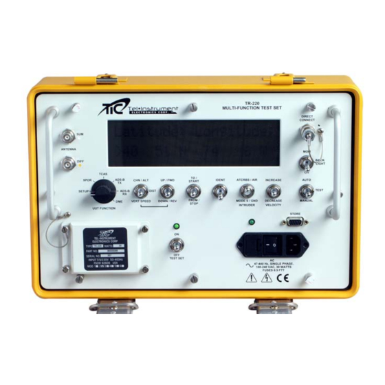
MULTIFUNCTION TEST SET
Transponder, TCAS, DME, TIS, and ADS-B
Operational Manual
Software Revision 3.40 and Later
A
B
C
D
E
P
R
S
T
U
Tel-Instrument Electronics Corp
www.telinstrument.com
TR-220
Test Set
REVISION
F
G
H
J
K
V
W
X
Y
Z
09 May 2007
728 Garden Street
Carlstadt, NJ 07072
(201) 933-1600
L
M
N
Advertisement
Table of Contents

Related Manuals for TIC TR-220

Summary of Contents for TIC TR-220
- Page 1 TR-220 MULTIFUNCTION TEST SET Transponder, TCAS, DME, TIS, and ADS-B Test Set Operational Manual Software Revision 3.40 and Later REVISION 09 May 2007 Tel-Instrument Electronics Corp 728 Garden Street Carlstadt, NJ 07072 (201) 933-1600 www.telinstrument.com...
- Page 2 Leading the AVIONICS TEST industry into the 21st Century! NOTICE: The information contained in this manual is subject to change without notice. Tel-Instrument Electronics Corp. makes no warranty of any kind to this material, nor shall be liable including but not limited to, errors contained herein or for incidental or consequential damages in connection with the furnishings, performance, or use of this material.
- Page 3 Safety Precautions The following are general safety precautions that are not related to a particular test or procedure. These are recommended procedures that all personnel must apply during many phases of operation and maintenance. It is assumed that the operator has general knowledge of electrical theory and the dangers associated with it.
- Page 4 ESD Safety and Protection Many parts contained in the Test Set are sensitive to ESD (Electro-Static Discharge) damage. ESD can damage integrated circuits or semiconductors located within the Test Set. Only qualified personnel should service the Test Set to prevent damage. The following are guidelines to avoid ESD damage while still performing tests and or maintenance.
- Page 5 VOLUME 1 OPERATIONAL PROCEDURES...
- Page 6 Rev E TR-220 90 008 088-1 TR-220 TABLE OF CHANGES Date Page Description Prelim. Initial Release 07 Sep 03 Initial Release 15 July 04 Updated procedure explanations 2-5 & 6, 13, 17, Provided Detailed EHS and ADS setup 16 Mar 05...
-
Page 7: Table Of Contents
Rev E TR-220 90 008 088-1 Table of Contents Chapter Page Table of Changes……………………………………………………………………. List of Illustrations…………………………………………………….……………… List of Tables……………………………………………………….………………… viii INTRODUCTION Section A- General Information Scope of Manual…………………………………………………………… Purpose and Function of Equipment…………………………………….. Regulatory Responsibilities…………………………………………..Warranty…………………………………………………………………….. 1.4.1 Obtaining Warranty Service…………………………………………... - Page 8 Rev E TR-220 90 008 088-1 Table of Contents (continued) Chapter Page Section B- Operating Controls, Indicators, and Connectors General………………………………………………………………... Controls, Indicators, and Connectors……………………………………. Section C- Operating Instructions General………………………………………………………………... Battery Operation…………………………………………………………… 2.8.1 Auto-Shutdown………………………………………………….. TR-220 Supplied Antenna…………………………………………………. 2.9.1 Directional Antenna…………………………………………….. 2.9.2 Direct Connect…………………………………………………..
-
Page 9: List Of Tables
Rev E TR-220 90 008 088-1 Table of Contents (continued) Chapter Page 2.18 ADS-B and TIS Testing……………………………………………………. 2-47 2.18.1 ADS-B TX……………………………………………………….. 2-47 2.18.2 ADS-B RX………………………………………………………. 2-50 2.19 RS-232 Download Procedures…………………………………………… 2-52 2.19.1 Setting Up your Computer for RS-232 Download………….. 2-53 2.19.2... -
Page 10: Introduction
TR-220 Multifunction Test Set Purpose and Function of the Equipment The TR-220 Test Set tests airborne ATCRBS, MODE A/C, and MODE S transponders, TCAS I/II systems, DME equipment, and ADS-B and TIS Transponders. It is self-contained and battery operated that requires no direct hardware connection to the Unit Under Test (UUT). -
Page 11: Regulatory Responsibilities
ADS-B squitters. The ADS-B RX function permits the operator to simulate a 1090MHz squitter. The TR-220 can be configured to transmit an airborne or surface position squitter containing position, altitude, velocity, heading, aircraft category, flight ID, and Mode S address. -
Page 12: Warranty
Rev E TR-220 90 008 088-1 Warranty The Tel-Instrument Electronics Corporation warrants that each product it manufactures is free from defective material and workmanship for a period of two (2) years subject to the following terms and conditions. Tel-Instrument Electronics Corp. will remedy any such warranted defect... -
Page 13: Shipping And Packing The Test Set
Rev E TR-220 90 008 088-1 • RMA Form on top of the product • The assigned RMA number written in bold letters on the outside of the shipping container • Model, Serial Number, specific details regarding problem • POC... -
Page 14: Section B
Rev E TR-220 90 008 088-1 SECTION B EQUIPMENT DESCRIPTION Specifications Transponder Transmitter Frequency 1030 MHz ± 10 kHz Output Power > 4dBm Modes A, C, S, ADS B TX/RX, and TIS Transponder Receiver Frequency Frequency 1086.5 to 1093.5 MHz Accuracy ±... - Page 15 Rev E TR-220 90 008 088-1 TCAS Receiver Frequency 1026.5 to 1033.5 MHz Power 47 to 64 dBm Physical Characteristics Packaging MIL-PRF-28800 Style C Size 14.5 x 9.4 x 6.5 inches Weight. 20 pounds Operating Temperature -28° to +55° C Battery Operation.
-
Page 16: Abbreviations, Acronyms, And Glossary Of Terms
Rev E TR-220 90 008 088-1 Abbreviations, Acronyms and Glossary of Term Air to Air A/A B Air to Air Beacon ac or AC Alternating Current Analog to Digital ADS-B Automatic Dependent Surveillance - Broadcast Address The unique code to which a MODE S transponder replies. This is not to be confused with the 4096 code used for identifying ATCRBS transponders. - Page 17 Rev E TR-220 90 008 088-1 MODE S A secondary radar system where transponders can be individually interrogated or selected (the “S” in MODE S) so that in a crowded air traffic area, the amount of interference or garble can be reduced to a minimum.
-
Page 18: Preparation For Use And Operation
TR-220 Multifunction Test Set (Hereinafter called the TR-220, Test Set, or T/S). Unpacking When receiving the TR-220 for the first time, ensure that there is no damage to the shipping container. Carefully unpack the unit and save the shipping container in a safe location for shipping or extended storage. - Page 19 Rev E TR-220 90 008 088-1 NOMENCLATURE Test Set 90000088 Cable Assembly, AC Power Cord 75010025 Cable Assembly, Direct Connect 75010186 Extender Cable Assembly, Directional 75010078 Antenna Directional Antenna Cable Assembly 75010208-02 Directional Antenna Assembly 89001158-07 Directional Antenna Handle Assembly...
-
Page 20: Section B- Operating Controls, Indicators, And Connectors
Rev E TR-220 90 008 088-1 SECTION B OPERATING CONTROLS, INDICATORS, AND CONNECTORS General This section covers location and function of the operating controls, indicators, and connectors. All controls, indicators, and connectors are located on the front panel of the Test Set. - Page 21 Rev E TR-220 90 008 088-1 Control, Indicator, or (Table 2-2) FUNCTION Connector Provides Connection to the Directional Antenna Sum Connector and the SUM Antenna Port optional TAP-135 Antenna Coupler. DIFF Antenna Port Provides Connection to the Directional Antenna Diff Connector...
-
Page 22: Section C- Operating Instructions
OPERATING INSTRUCTIONS General The TR-220 is a self-contained instrument comprised of a Test Set mounted in a rugged case with a removable cover. The Test Set front panel contains all the switches necessary to test Transponders (ATCRBS and MODE S), ADS-B and TIS, DME and TCAS equipment. By the use of toggle switches and an easy to read display, the operator may quickly test, make accurate measurements and perform preprogrammed or manually selected TCAS scenarios. -
Page 23: Auto-Shutdown
Shutdown will not occur when AC power is utilized as the source. TR-220 Supplied Antenna Standard equipment with the TR-220 is a Directional Antenna. The antenna, stored in the case cover, can either be hand held, tripod mounted, or directly mounted on the Test Set case. The Test Set also contains a direct connect cable for accurate power and frequency measurements (±... -
Page 24: Directional Antenna Gain
Rev E TR-220 90 008 088-1 Locate the ANT GAIN menu by toggling the AUTO/MANUAL switch. Enter the correct values that are affixed to the Directional Antenna (Figure 2-3) by using the UP/FWD, DOWN/REV switch. Ensure you enter both values, 1030 MHz and 1090 MHz. -
Page 25: Directional Antenna Setup
Rev E TR-220 90 008 088-1 NOTE: The TR-220 uses a software technique to narrow the beam width. When testing inside of a hanger, multi-path reflections can cause erroneous TURN indications. If unable to eliminate TURN message, remove antenna cable connection to DIFF port. -
Page 26: Direct Connect
The TR-220 has a built in 50 dB attenuator, thus eliminating the need to connect an external attenuator for power and frequency measurements. - Page 27 TR-220 90 008 088-1 TAP-200 Coupler Figure 2-5 Connect the TAP-200 Cable to the TR-220 antenna SUM port. Turn the test set ON by toggling the ON/OFF switch Up and turn the UUT FUNCTION switch to the SETUP position. Scroll to the Antenna Selection screen using the AUTO/MANUAL switch.
-
Page 28: Tap-200 Placement
Rev E TR-220 90 008 088-1 Center the TAP-200 as close to center as possible for the style of antenna being tested. If inaccurate results occur, reposition the coupler slightly forward or back and check for a snug flush fit until accurate measurements are displayed. -
Page 29: Initial Startup And Self-Test
When using the Test Set, it is advisable to have a fully charged battery. This will ensure all tests can be completed with no interruptions or loss of data. Turn on the TR-220 by toggling the ON/OFF switch “UP”. The green LED located above the switch will illuminate. Briefly, the Test Set display will indicate: Model number, current software version installed and total hours of operation. -
Page 30: Transponder Test Sequence
2.11 Transponder Test Sequence The TR-220 T/S is capable of testing ATCRBS Mode A, Mode C and Mode S transponders. The operator may select between an Automatic series of tests and a Manual series of tests. Figure 2- 8 outlines the sequence, in order, of tests conducted. The Test Set will determine the correct set of tests, either Mode A/C or Mode S upon receiving the transponder RF signal. -
Page 31: Transponder Manual Sequence Of Tests
Rev E TR-220 90 008 088-1 2.12 Transponder Manual Sequence of Tests All illustrations shown are for demonstration purposes. Though the test NOTE results may be typical, they are not meant to replace FAA guidelines and manufacturer recommendations. When conducting tests in the MANUAL sequence, the operator initializes the sequence by toggling the AUTO/TEST/MANUAL switch to the MANUAL position. - Page 32 Rev E TR-220 90 008 088-1 Test Complete. Display indicates the UUT M A 1234 100% 4096 Octal Code (1234), Receiver 0.45–20.35– 0.45 PASS Efficiency percentage (100%), Transponder Framing Pulse widths (0.45) and separation measured in .05 µs increments (20.35 µs).
- Page 33 Rev E TR-220 90 008 088-1 A: -73.9dB C: -73.9dB Test Completed. Display indicates the UUT Sens. A&C: PASS receiver sensitivity for mode A (-73.9db) and Mode C (-73.9dB) PASS is displayed when Mode A/C sensitivities are within 1dB. To advance, toggle the AUTO/TEST/MANUAL switch to MANUAL. The next test in sequence will commence.
-
Page 34: Mode S Manual Testing
Rev E TR-220 90 008 088-1 2.12.2 Mode S Manual Testing Turn the Test Set “ON” by toggling the ON/OFF switch to the ON position. Ensure the green LED illuminates. Utilize the procedures as outlined in 2.9 to select the preferred antenna method for the following tests. - Page 35 Rev E TR-220 90 008 088-1 Test Complete. Display indicates the UUT M C 6520 10000’ 100% Altitude Gray Code (6520=1000’), Rcvr. 0.45-20.35-0.45 PASS Efficiency percentage (100%), Transponder Framing Pulse widths (0.45) and separation measured in .05 µs increments (20.35 µs).
- Page 36 Rev E TR-220 90 008 088-1 M A Only Mode A ONLY Test initialized. Test Set transmits an ATCRBS ONLY All-Call. Testing . . . A Mode S transponder will not reply to an M A Only ATCRBS Only All-Call. A “PASS” signifies PASS the Mode S transponder did not respond.
- Page 37 Rev E TR-220 90 008 088-1 Toggle the AUTO/TEST/MANUAL switch to MANUAL to advance to the next sequence: M S Surv Alt Mode S Surveillance Altitude Test. Test Set will transmit an UF=4 interrogation. Testing . . . Test complete. A successful DF=4 Reply M S Surv Alt will display reported altitude (10000’) and...
- Page 38 Rev E TR-220 90 008 088-1 M S Comm Alt Mode S Communication Altitude Test. Test Testing . . . Set will transmit a COMM A/B transmission utilizing the UF=4/RR:18 format. This tests the transponders communication and data- link capabilities.
- Page 39 Rev E TR-220 90 008 088-1 Max True Spd Test Set verifies the UUT airspeed code by transmitting an UF=0 interrogation. Testing . . . Max True Spd Test complete. The DF=0 will report the aircraft maximum cruising airspeed in the GT 300 &...
- Page 40 Rev E TR-220 90 008 088-1 Mode S Width Ampl. Test Complete. Display indicates the Mode S Reply Delay, Mode S Jitter, Mode S P6 Testing . . . Amplitude Variation, and Mode S P6 Pulse Width with a P(ass) or F(ail) indication for each measurement.
-
Page 41: Transponder Automatic Sequence Of Tests
Rev E TR-220 90 008 088-1 2.13 Transponder Automatic Sequence of Tests When conducting tests in the AUTO sequence, the operator initializes the sequence by toggling the AUTO/TEST/MANUAL switch to the AUTO position. The Test Set then commences a series of tests without interruption (see figure 2-8) ending in the POWER, RECEIVER EFFICIENCY and FREQUENCY page. - Page 42 Rev E TR-220 90 008 088-1 If no failures are detected, the Test Set will cease testing and display the following alternating display: Power, Receiver, Freq / The final alternating display will indicate 54dB -78dB 1090.0 power (54dB), Receiver Sensitivity...
-
Page 43: Mode S Automatic Testing
Rev E TR-220 90 008 088-1 2.13.2 Mode S Automatic Testing Turn the Test Set “ON” by toggling the ON/OFF switch to the ON position. Ensure the green LED illuminates. The Test Set commences the Self Test. “PASS” is displayed briefly if no failures are detected. - Page 44 Rev E TR-220 90 008 088-1 If a failure is detected during any test in the Automatic sequence, the Test Set will “STOP” at that test and display the failure along with the Framing Pulses- Pulse Width and separation in µs.
-
Page 45: Testing A Transponders "Ident" Function
Rev E TR-220 90 008 088-1 2.14 Testing a Transponders “IDENT” Function The “IDENT” function can only be tested in the Manual mode of Tests in NOTE both Mode A/C and Mode S. 1. To test the “IDENT” feature of a transponder the operator may select the Mode A or the M C Test for the appropriate transponder (Mode A/C or Mode S). -
Page 46: Tcas Tests
2.15 TCAS Tests The TR-220 Multifunction Test Set is capable of fully testing ATCRBS and Mode S, ACAS, TCAS I, and II systems (Traffic Alert and Collision Avoidance System). The operator is able to manually select a scenario or utilize the default scenario already preprogrammed in the Test Set Memory. -
Page 47: Tcas Scenario Selection And Setup
AREA. 2.15.2 TCAS Scenario Selection and Setup To TR-220 must have the correct values entered to properly program an intruder to converge with the UUT aircraft. If the intruder scenario is incorrectly programmed, the operator may not receive the anticipated results. - Page 48 Rev E TR-220 90 008 088-1 and stored in the Test Set Memory. By toggling the UP/FWD-DOWN/REV switch, the operator can select the appropriate intruder scenario. TCAS Scenario: Chg:Up/Dn Cont: AUTO After selecting a suitable scenario, the operator needs only to turn the UUT FUNCTION switch to the TCAS position to begin an intruder simulation.
- Page 49 Rev E TR-220 90 008 088-1 Toggle the AUTO/TEST/MANUAL switch to the AUTO position to advance to the Velocity menu. Utilize the UP/FWD-DOWN/REV switch to set the velocity to the desired setting. The Velocity is adjustable from 120Kts to 1200Kts.
- Page 50 The operator is able to select an infinite number of simulated Intruder scenarios. The TR-220 allows the user to select Intruder Starting Altitude, Vertical Speed, and Distance from target, and three preset Velocities. Table 2-4 describes each parameter and limitations.
- Page 51 Rev E TR-220 90 008 088-1 (10,000 – 20,000) x 600 VS = ---------------------------------------------- 20 x 60 Complete the equation to find the correct Vertical Speed (VS) value to be entered. -6,000,000 VS = -------------------------------- 12000 VS = -5000 The correct Vertical Speed variable is -5000 fpm.
-
Page 52: Erasing The Tcas Scenario Memory
Rev E TR-220 90 008 088-1 2.15.3 Erasing the TCAS Scenario Memory The TCAS memory can be restored to factory settings by the following procedures: Place the UUT FUNCTION switch in the SETUP position. Access the TCAS Scenario menu by toggling the AUTO/TEST/MANUAL switch. -
Page 53: Testing A Tcas Equipped Aircraft
Rev E TR-220 90 008 088-1 2.15.4 Testing a TCAS Equipped Aircraft Connect the Directional Antenna to the Test Set IAW Paragraph 2.9.1. The Directional Antenna is the only antenna that may be utilized for TCAS testing. Turn the Test Set “ON” by toggling the ON/OFF switch to the ON position. - Page 54 Rev E TR-220 90 008 088-1 Select the intruder type, Mode S or ATCRBS using the ATCRBS/AIR-MODE S/GND switch. For TCAS I select ATCRBS and for TCAS II select Mode S. Toggle the AUTO/TEST/MANUAL switch to the AUTO position. The Test Set is now simulating an intruder aircraft at the selected position.
- Page 55 Rev E TR-220 90 008 088-1 The operator may now observe the AUT TCAS display to ensure correct operation. Once the simulated intruder’s range has reached 0 nmi, the Test Set will reverse the heading and return back to the start point. This will continue, back and forth, until the operator stops the simulation.
- Page 56 Rev E TR-220 90 008 088-1 TRK 600Kts 30000’ / 30 nm -5000fpm STP 14d. As the simulated intruder approaches, the altitude will decrease to ensure a proper intersect of the targets. TRK 600Kts 23000’ / 15.9 nm -5000fpm TO 14e.
- Page 57 Rev E TR-220 90 008 088-1 TRK 600Kts 16150’ / 2.1 nm -5000fpm FRM It is possible to adjust the scenario parameters without changing the stored parameters within the Setup Menu. With the UUT FUNCTION switch in the TCAS position and with the TCAS scenario window displayed, proceed as follows: TRK 600Kts 16150’...
-
Page 58: Dme Tests
2.16 DME Tests The TR-220 is capable of selecting any of the DME frequencies of 108.0 – 117.95 MHz channels. The Test Set simulates a ground station at an operator selected range and velocity. When the operator initiates the test, the Test Set range, TO or FROM, will decrease to 0 nmi., and return back to the pre-selected range. - Page 59 Rev E TR-220 90 008 088-1 At any point during the test, the operator may reverse the direction of the simulation by toggling the TO/START-FROM/STOP switch “DOWN” to the FROM/STOP position. The scenarios will then, stop and reverse direction. The TO display will change to FROM indicating FROM the AUT.
-
Page 60: Mode S Enhanced Surveillance
ACTUAL results The TR-220 is capable of testing Mode S Transponders with Enhanced surveillance (EHS) capability. Access to the EHS menu is as follows: If utilizing the Directional Antenna, select SETUP using the UUT FUNCTION switch and complete the procedures in paragraph 2.9.1. - Page 61 Rev E TR-220 90 008 088-1 Press the AUTO/TEST/MANUAL switch to continue. The Roll angle will be displayed in degrees. Part of the BDS5 Track and Turn report. BDS5 Roll Angle Press AUTO/TEST/MANUAL to move to the next test. The True track angle will displayed in degrees and the Track Angle rate will be displayed in degrees per second.
- Page 62 Rev E TR-220 90 008 088-1 The TR-220 will decode and display parameters contained in the BDS 1,0 register. The parameters include, Mode S Subnet Network Number = “Sub Net=0” (Decode and display IAW with ICAO Annex X Volume 3 Sect. 5.2.9 (page 279) 0,1,2, 3, etc.);...
- Page 63 Press AUTO/TEST/MANUAL to move to the next test. The display will indicate if TCAS has issued a Resolution Advisory. BDS3 ACAS Active Resolution Advisory. A second TR-220 may be necessary to simulate a TCAS intruder in order to cause the TCAS system to issue a Resolution Advisory NOTE BDS Resolution Adv: Active RA FFFFFF Press AUTO/TEST/MANUAL to move to the next test.
-
Page 64: Ads-B And Tis Testing
2.18 ADS-B and TIS Testing The TR-220 Test Set provides operators with the capability to test ADS-B and TIS functions that are now standard in many models of Transponders. This is an enhancement over standard MODE S transponder that provides operators with unique information previously not available. - Page 65 AUTO_TEST_MANUAL switch to MANUAL. This will store the latitude and longitude information in the test set HOME POSITION. To set the Lat & Lon positional information into the TR-220, proceed as follows. Turn the test set ON with the UUT FUNCTION switch in the set up position.
- Page 66 Press the AUTO/TEST/MANUAL switch to select the next screen: Mode S Address . . . The TR-220 will decode and display the Aircraft Mode S Address as shown in the following display. In addition, the TR-220 decodes and displays the Interrogator Identifier (II) field.
-
Page 67: Ads-B Rx
FUNCTION and using the AUTO/TEST/MANUAL switch to select Mode S Address (The Mode S address for the other 3 targets will be incremented by 1). The TR-220 will transmit the DF17 or DF18 information for 4 intruder aircraft that have the following parameters when AIRBORNE intruder is selected: a. - Page 68 Rev E TR-220 90 008 088-1 The TR-220 will transmit the DF17 or DF18 information for 4 intruder aircraft that have the following parameters when GND intruder is selected: a. Distance = 1 mile from the test set HOME POSITION b.
-
Page 69: Rs-232 Download Procedures
2.19 RS-232 Download Procedures The TR-220 contains memory to down load results received during the AUTOMATIC sequence of tests to a PC thru the use of the RS-232 port located on the front panel of the Test Set. Once downloaded, the information can be displayed in an Excel file to be viewed and saved for future reference. -
Page 70: Setting Up Your Computer For Rs-232 Download
Once this is accomplished, the operator can then sort the data in the excel file in any way they prefer. The TR-220 Test Set utilizes a Hyper Terminal Program that is part of the Microsoft Windows Operating System. If this is not installed on your computer, you can obtain the program from the Microsoft Website or from your Windows Software the was supplied with your Computer. -
Page 71: Downloading The Data
TR-220 90 008 088-1 Close the Program. You have not created a permanent short cut configured for the TR-220 RS-232 download feature. You will not be required to repeat this procedure. When preparing to download data, select the TR-220 Hyper Terminal that should be located within the Hyper Terminal program selection dropdown. -
Page 72: Loading The Data To A Microsoft Excel File
Rev E TR-220 90 008 088-1 2.19.3 Loading the Data to a Microsoft Excel File Open up Microsoft Excel; do not double click on the file stored on the computers Desktop. Select FILE then OPEN. Locate the file on the Desktop (or wherever it was saved to) and open the file.
Need help?
Do you have a question about the TR-220 and is the answer not in the manual?
Questions and answers