
Summary of Contents for Duramaxx 90010
- Page 1 55 lbs TROLLING MOTOR MODEL: 90010 Owner's Manual TOLL F REE HELPLINE: 1 866 456-8934 WARNING CAUTION READ THIS MANUAL CAREFULLY BEFORE OPERATING YOUR DURAMAXX TROLLING MOTOR. RETAIN FOR FUTURE REFERENCE.
-
Page 2: Table Of Contents
PROPELLER REPLACEMENT ......................MAINTENANCE ..........................TROUBLESHOOTING......................... LIMITED WARRANTY.........................13 EXPLODED VIEW ..........................PARTS LIST ............................SPECIFICATIONS MODEL NO ..........................90010 MOTOR ............................12 V THRUST ............................55 lbs PROP SPEED ........................2000 RPM FORWARD SPEED ......................5 SPEEDS REVERSE SPEED ......................3 SPEEDS... -
Page 3: Feature Information
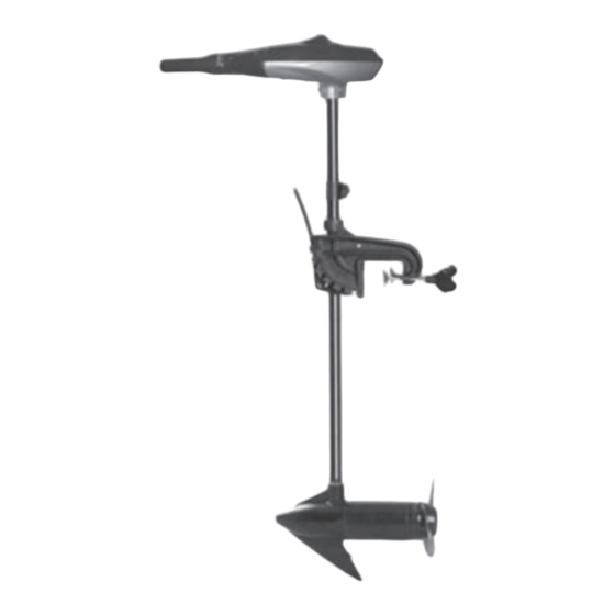
FEATURE INFORMATION Tilt Twist Battery Meter Tiller Handle Depth Collar Knob Tilt lock lever Boat mounting bracket Clamp Screws Adjustable shaft Propeller 12 V DC Motor... -
Page 4: Adjustment
ADJUSTMENT MOUNTING THE MOTOR Install the motor on the transom of the boat. Be sure to tighten the clamp screws securely. WARNING: When tilting motor, keep fingers clear of all hinge and pivot points and all moving parts. CAUTION: Over-tightening the clamp screws can damage the bracket. Tighten Loosen... - Page 5 ADJUSTMENT BRACKET ADJUSTMENT You can lock your motor in a vertical position, angle it for shallow water or tilt it completely out of the water. • Firmly grasp the control head or steel shaft. • Depress and hold the tilt lock lever. •...
- Page 6 ADJUSTMENT DEPTH ADJUSTMENT • Firmly grasp the shaft and hold it steady. • Loosen the steering tension knob and depth collar knob until the tube slides freely. • Raise or lower the motor to the desired depth. • Tighten depth collar knob to secure the motor in place. IMPORTANT: When setting the depth, be sure the top of the motor is submerged at least 12”...
-
Page 7: Operation
OPERATION TILT TWIST TILLER These motors offer a choice of five forward and three reverse speeds. The speed control may be operated in either direction, forward or reverse. • Turn the tilt twist tiller handle counterclockwise from O (off) to increase reverse speed. •... -
Page 8: Battery
BATTERY 12 V BATTERY INFORMATION The motors will operate with any deep cycle marine 12 V battery. For best results it is recommended to use a deep cycle marine battery with a minimum of 105 ampere hour rating. As a general on the water estimate, your 12 V motor will draw one ampere per hour for each pound of thrust produced when the motor is running on high. -
Page 9: Battery Connection
BATTERY BATTERY CONNECTION 12 V Systems 1. Connect the positive (+) red lead to the positive (+) battery terminal. 2. Connect the negative (-) blace lead to the negative (-) battery terminal. NOTE: If installing a leadwire plug, observe proper polarity and follow instructions in your boat owner’s manual. -
Page 10: Propeller Replacement
PROPELLER REPLACEMENT PROPELLER REPLACEMENT • Hold the propeller and loosen the prop nut with a pliers or a wrench. • Remove prop nut and washer. NOTE: If the drive pin is sheared/broken, you will need to hold the shaft steady with a screwdriver blade pressed into the slot on the end of the shaft. -
Page 11: Maintenance
MAINTENANCE • After use, these units should be rinsed with fresh water, then wiped down with a cloth dampened with an aqueous based silicone spray. • The propeller must be cleaned of weeds and fishing line. The line can get behind the prop, wear away the seals and allow water to enter the motor. -
Page 12: Troubleshooting
4. Your experience prop vibration during normal operation: • Remove and rotate the prop 180º. See removal instructions in prop section. NOTE: If you do not understand the warnings and instructions in this Owner's manual, do not use this product. Call DURAMAXX customer service for assistance. -
Page 13: Limited Warranty
LIMITED WARRANTY 2 —Year Limited Warranty THIS WARRANTY IS NOT TRANSFERABLE AND DOES NOT COVER: Products sold damaged or incomplete, sold “as is”, sold reconditioned or used as rental equipment. Delivery, installation or normal adjustments explained in the owner’s manual. Damage or liability caused by shipping, improper handling, improper installation, incorrect voltage or improperwiring, improper maintenance, improper modification, or the use of accessories and /or attachments not specifically recommended. -
Page 14: Exploded View
EXPLODED VIEW... -
Page 15: Parts List
PARTS LIST Description. Parts Num. Model Num. 34130193 Tiller handle 33106193 Aluminum tube Actuator 34131193 34103193 Handle (top half) 34108193 Bearing-handle pivot 33401193 Spring-detent 34105193 Actuator-cam 34106193 Pot adapter 33402193 Spring Release button 34107193 34104193 Handle (Lower half) 3220505 Screw 3411435 Cord retainer 3220511...