andrews WHC56 Installation And Service Manual
Condensing gas water heater
Hide thumbs
Also See for WHC56:
- Service manual (40 pages) ,
- Installation design manual (12 pages) ,
- Owner's manual manual (36 pages)
Table of Contents
Advertisement
Quick Links
Advertisement
Table of Contents

Related Manuals for andrews WHC56


Summary of Contents for andrews WHC56
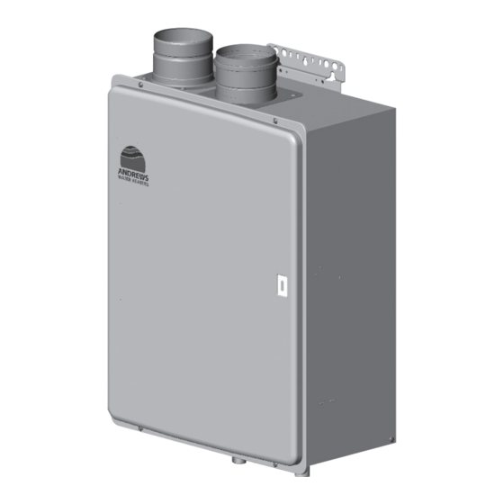
- Page 1 INSTALLATION AND SERVICE MANUAL Part number E890 CONDENSING GAS WATER HEATER WHC56, LWHC56 (Internal) SBA8198-3 Please read and understand these instructions before commencing installation and leave this manual with the customer for future reference. Andrews. Built to perform.
- Page 3 CONDENSING GAS WATER HEATER Business Centre, Oaklands Park, Wokingham, Berkshire, RG41 2FD PRODUCT : NORITZ CORPORATION WHC56, LWHC56 (Internal) 5, Minamifutami, Futami-cho, Akashi, Hyogo, Japan WARNING: If the information in this manual is not followed exactly, a fire or explosion may result causing property damage, personal injury or death.
- Page 4 The following accessories are included with the unit. Included Accessories Check for any missing items before starting installation. Part Shape Part Shape Q’ty Q’ty Installation Manual Owner's Guide (this document) Tapping Screw The accessories listed below are not Optional Accessories included with the units, but may be necessary for installation.
- Page 5 WHC56 LWHC56 140W 140W 170W 170W Freeze Preventive Heater G20 20mbar G31 30/37mbar 10.0mbar 12.9mbar 2.7mbar 3.0mbar 55.8kW 55.8kW (CONDENSING) 2.98kW 2.98kW (CONDENSING) 54.0kW 54.0kW 3.20kW 3.20kW GB&IE GB&IE...
- Page 6 Quick Connect Multi System Installation • The Quick Connect Multi System allows the installation of two units together utilizing only the Quick Connect Cord. The Quick Connect Cord is 2m. long. Install the two units 470mm-950mm apart at the center to ensure the cord will be able to reach between the units.
-
Page 7: Before Installation
Before Installation Warning Precautions on replacement of equipment • Replace the intake and exhaust pipe, the flue terminal and the fixing bracket with new one as a general rule. However, the material of intake and exhaust pipe, flue terminal or fixing bracket is equivalent to SUS304 or more, these parts can be reused. - Page 8 The appliance must be installed in a Choosing Installation Site suitably ventilated room, in accordance with the regulatins in force. * Locate the appliance in an area where leakage from the unit or connections will not result in damage to the area adjacent to the appliance or to the lower floors of the structure. When such locations cannot be avoided, it is recommended that a suitable drain pan, adequately drained, be installed under the appliance.
- Page 9 • Do not install the water heater where the exhaust will blow on outer walls or material not resistant to heat. Also consider the surro- unding trees and animals. The heat and moisture from the water heater may cause discolo- ration of walls and resinous materials, or corrosion of aluminum materials.
-
Page 10: Installation Clearances
Installation Clearances Caution Before installing, check for the following: The appliance must be installed in a suitably ventilated room, in accordance with the regulations in force. Install in accordance with relevant building and mechanical codes, as well as any local, state or national regulations. -
Page 11: Installation
Installation Securing to the wall • The weight of the device will be applied to the wall. If the strength of the wall is not suffi- cient, reinforcement must be done to prevent the transfer of vibration. • Do not drop or apply unnecessary force to the device when installing. Internal parts may be damaged and may become highly dangerous. - Page 12 Filling the drain trap unit with water The drain trap unit can be filled before connecting the vent pipe. Filling the drain trap unit before vent pipe installation. Prior to initial start up, make sure that you fill the drain trap unit with water. DANGER This is to prevent dangerous exhaust gases from entering the building.
-
Page 13: Flue Pipe Installation
Flue Pipe Installation Flue Terminal Installation • Follow the installation instructions included with the flue terminal and which are reproduced at the end of this manual. This appliance must be the flue through the wall, not vertically to the roof. Flue Terminal Installation Precautions Note the following flue terminal installation requirements •... - Page 14 Note: An adapter is always required on top of the heater. For the vertical flue set up, offset adapter will be supplied for the air intake. a) The flue system must be constructed using only Andrews Water Heaters approved components.
- Page 15 • VERTICAL FLUE TERMINAL Pitched roof Straight roof Flat roof Pitched roof Air and flue adapter Air and flue adapter Heater to flue adapter Special adapter • HORIZONTAL FLUE TERMINAL (SHORT) • HORIZONTAL FLUE TERMINAL (LONG) ° bends Standard length cut to 7000 4 x 90 Maximum length...
- Page 16 • Install the flue terminal so that it is easily acces- • If possible, don’t install the flue pipe through any sible for maintenance both from the indoors and enclosed areas.If necessary,consult ANDREWS the outdoors. WATER HEATER for clearances. • Install the flue terminal so that all exhaust is di-...
- Page 17 • Install the flue terminal so that it is easily acces- any enclosed areas. If necessary, consult sible for maintenance both from the indoors and ANDREWS WATER HEATER for clearances. the outdoors. • Install the flue terminal so that all exhaust is directed to and all intake air is taken from outdoors.
- Page 18 When the intake/exhaust pipes pass through an enclosed space: Intake pipe Exhaust pipe Sloping up toward flue terminal (Combustible material) Ceiling External wall, combustible material Suggested inspection openings • If the ventilation of hidden part is not sufficient, install two or more ventilation holes.
-
Page 19: Gas Piping
Gas Piping Follow the instructions from the gas supplier. The appliance and its individual shutoff valve must be disconnected from the gas supply piping system during any pressure testing of that system at test pressures in excess of 35 mbar. The Appliance must be isolated from the gas supply piping system by closing its individual manual shutoff valve during any pressure testing of the gas supply piping system at test pressures equal to or less than 35 mbar. -
Page 20: Water Piping
If the water heater is installed in a closed water supply system, such as one having a backflow preventer in the cold water supply line, means shall be provided to control thermal expansion. Contact ANDREWS WATER HEATERS TECHNICAL DEPARTMENT FOR ADVICE. -
Page 21: Electrical Wiring
Consult a qualified electrician Electrical Wiring for the electrical work. Do not connect electrical power to the unit until all electrical wiring has been completed. i) "A means of disconnection from the supply mains having a contact separation in all poles must be pro- vided to allow for full disconnection". - Page 22 Remote Controller • Applicable Model WHC56, LWHC56 Main Remote controller RC-7508M The remote controller must be installed in accordance with the installation manual enclosed in the • package. Connecting Remote Controller Cord to Unit • Keep the remote controller cord away from the freeze prevention heaters in the unit.
- Page 23 The installer should test operate the unit, explain to Commissioning the customer how to use the unit, and give the owner this manual before leaving the installation NOTE: The appliance has been factory set and no adjustment is necessary. • Preparation ... (1) Ensure all lines are purged / flushed of debris prior to connection to appliance. (2) Open the shut off valve on the water supply, check that water passes through the valve and close the valve.
-
Page 24: Drain Piping
Drain Piping Contact an authorized office of the area when requesting work and be sure to follow sewage laws. Drain pipe • This product is a highly-efficient latent heat collection device and drain water is discharged from the drain discharge port during combustion (max discharge: about 100cc/min). Be sure to perform drain piping. - Page 25 Dimensions WHC56, LWHC56 < mm > 4- 13 6-6 x 10 OBLONG HOLE EXHAUST PIPE AIR INLET CONNECTION 100.8 (OUTER) 101.5 (INNER) UPPER WALL MOUNT BRACKETS OPERATION LAMP LOWER WALL MOUNT BRACKETS WATER DRAIN VALVE WIRING THROUGHWAY (WATER FILTER) (POWER CORD)
- Page 26 Wiring Diagram (WHC56, LWHC56) HEAT EXCHANGER (Pulse) (Vcc) FLOW SENSOR (GND) WATER LEVEL (GND) ELECTRODE 2 EXTERNAL POWER CHANGE 3P CONNECTOR (OPTIONAL) <CN89> WW W <CN102> CHANGE GAS CATEGORY WATER INLET 1 2 3 4 5 6 1 2 3 4 5 6...
- Page 27 For Installers: Remote Controller Installation Manual Read this installation guide carefully before carrying out installation. Model Number: RC-7508M Note Do not connect power to the water heater before the remote controller has been properly installed. Included Accessories Part Shape Part Shape Q’ty Q’ty...
-
Page 28: Disassembly Of Each Part
Do not use reconditioned or copy parts that have not been clearly authorised by Andrews Water Heaters. Before commencing with a service or replacement of parts the boiler should be isolated from the electrical supply and water supply and the gas supply should be turned off at the gas service cock. - Page 29 (2) Remove the quick fastener (A) in the right figure and pull the bypass servo (B). (3) Unscrew two fixing screws (A and B) in the right figure and remove the transformers. 2. How to remove the board (1) Unscrew two screws (A and B) that fix the board and the earth screw (C) and remove the board.
- Page 30 3. How to remove the manifold - Unscrew two fixing screws of mounting plate for current leakage safety device in advance. (1) Remove the quick fastener (A) in the right figure and slide the gas pipe (B) upward. (2) Unscrew four screws that fix the manifold and pull out the manifold SET.
-
Page 31: Servicing Parts Lists
Servicing parts lists External outfitting LWHC56,WHC56... - Page 32 External outfitting LWHC56,WHC56 Part Nos. Part Names Order Nos. Q'ty/unit GQC3252WZFFAD Front set-AS SKF7137 Front packing S AAPL015 Front packing L AAPL017 Caution label FF AD ELEK077 Lamp seal plate DECK008 Intake pipe packing EHKL084 Intake pipe ELEF001 Case set FF...
- Page 33 Combustion unit and gas route LWHC56,WHC56...
- Page 34 Combustion unit and gas route LWHC56,WHC56 Part Nos. Part Names Order Nos. Q'ty/unit Combustion tube set ELV SET-V SKC7447 Suction air joint packing ELVL001 Ignition plug ELV & packing EHK SETV SKC7448 Plug packing H EHKL002 Mounting plate for plug H EGLC035 Flame rod ELV &...
- Page 35 Hot-water feed route LWHC56,WHC56 (Thermal fuse rounding procedure) ( BACK ) ( FRONT ) ( RIGHT SIDE ) ( LEFT SIDE ) THERMAL FUSE FASTENER FASTENER HEAT EXCHANGER Begin winding up FASTENER...
- Page 36 Hot-water feed route LWHC56,WHC56...
- Page 37 Hot-water feed route LWHC56,WHC56 Part Nos. Part Names Order Nos. Q'ty/unit Heat exchanger & Exhaust box H ENJ SET-AS SKD7963 Thermal fuse(ADSE) EPJ SET-V SKF7165 Freeze preventive heater 3 DJW DJWH003 Dummy heater for 240V DJW DJWH004 Freeze preventive heater EPJ SETV...
- Page 38 Hot-water feed route LWHC56,WHC56 Part Nos. Part Names Order Nos. Q'ty/unit Hose clamp NO.39 SAD6531 Quick fastener 16-25 SAD6593 Quick fastener 6-13 SAD6594 Drain coupling CBND018 Lead clamper 70 HBNL001 Mounting plate for neutralizer EHWA016 Secondary heat exchanger H set...
- Page 39 Electronic control unit,Remote controller and Attached set LWHC56,WHC56 Electronic control unit For 3P Remote controller Kitchen remote controller RC-7508M Attached set <Special part> Special part Special part no. Owner's guide Installation manual...
- Page 40 Electronic control unit,Remote controller and Attached set LWHC56,WHC56 Part Nos. Part Names Order Nos. Q'ty/unit Relay case (ADSE)ENG-B SET-AS SHB7143 Relay case cover DEKA014 Relay case waterproof cover ELVA059 Harness EPJJ021 Lamp cable conduit CRPJ014 gas type switch connector DJP DJPJ011 1<3P>...
-
Page 41: Specifications
• Specifications may be changed without prior notice. Specifications • The capacity may differ slightly, depending on the water pressure, water supply, piping conditions, and water temperature. Item Specification Model Name WHC56 LWHC56 Type Internal, Wall Mounted Installation Air Supply/Exhaust Power Vented... - Page 42 ErP-Information Technical parameters Fastflo Fastflo Fastflo Fastflo Fastflo Fastflo Fastflo Fastflo Product name WH42 WH56 LWH42 LWH56 WHC56 LWHC56 WHX56 LWHX56 Daily electricity 0.297 0.297 0.33 0.33 0.337 0.33 0.271 0.276 elec consumption Declared load profile Sound power level, indoors...
- Page 44 Conditions of Sale which are available on request. July 2016 Customer support Monday - Friday 8am - 5pm 0345 070 1058 ICOM 0345 070 1059 Energy Association Email service@baxicommercialdivision.co.uk Website andrewswaterheaters.co.uk Twitter @AndrewsWH 500403 Andrews. Built to perform.