Table of Contents
Advertisement
QQ
3 7 63 1515 0
S
ervice
M anua l
BRIDGEABL FOUR-CHANNEL POWER AMPLIFIER
GM-X1024
GM-X924
TE
L 13942296513
CONTENTS
1. SAFETY INFORMATION ............................................2
2. EXPLODED VIEWS AND PARTS LIST .......................2
3. SCHEMATIC DIAGRAM .............................................8
4. PCB CONNECTION DIAGRAM ................................14
www
5. ELECTRICAL PARTS LIST ........................................19
6. ADJUSTMENT..........................................................25
.
PIONEER ELECTRONIC CORPORATION
PIONEER ELECTRONICS SERVICE INC.
PIONEER ELECTRONIC [EUROPE] N.V.
PIONEER ELECTRONICS ASIACENTRE PTE.LTD. 501 Orchard Road, #10-00, Lane Wheelock Place, Singapore 23880
C PIONEER ELECTRONIC CORPORATION 1998
x
ao
u163
y
i
P.O.Box 1760, Long Beach, CA 90801-1760 U.S.A.
Haven 1087 Keetberglaan 1, 9120 Melsele, Belgium
http://www.xiaoyu163.com
2 9
8
GM-X1024/X1R/UC
X1R/UC,EW ,ES
Q Q
3
6 7
1 3
1 5
7. GENERAL INFORMATION .......................................26
7.1 IC ........................................................................26
7.2 DISASSEMBLY ...................................................27
7.3 BLOCK DIAGRAM ..............................................28
8. OPERATIONS AND SPECIFICATIONS.....................29
co
.
4-1, Meguro 1-Chome, Meguro-ku, Tokyo 153-8654, Japan
9 4
2 8
ORDER NO.
CRT2191
X1R/UC
0 5
8
2 9
9 4
2 8
m
K-FED. MAR. 1998 Printed in Japan
9 9
9 9
Advertisement
Table of Contents

Related Manuals for Pioneer GM-X1024


Summary of Contents for Pioneer GM-X1024
-
Page 1: Table Of Contents
P.O.Box 1760, Long Beach, CA 90801-1760 U.S.A. PIONEER ELECTRONIC [EUROPE] N.V. Haven 1087 Keetberglaan 1, 9120 Melsele, Belgium PIONEER ELECTRONICS ASIACENTRE PTE.LTD. 501 Orchard Road, #10-00, Lane Wheelock Place, Singapore 23880 C PIONEER ELECTRONIC CORPORATION 1998 K-FED. MAR. 1998 Printed in Japan... -
Page 2: Safety Information
GM-X1024,GM-X924 3 7 63 1515 0 1. SAFETY INFORMATION CAUTION This service manual is intended for qualified service technicians; it is not meant for the casual do-it-yourselfer. Qualified technicians have the necessary test equipment and tools, and have been trained to properly and safely repair complex products such as those covered by this manual. -
Page 3: Te L 13942296513
See Contrast table (2) * 10-3 Warranty Card See Contrast table (2) 10-4 Owner's Manual See Contrast table (2) (2) CONTRAST TABLE GM-X1024/X1R/UC, GM-X924/X1R/UC, GM-X924/X1R/EW and GM-X924/X1R/ES are constructed the same except for the following: Part No. GM-X1024 GM-X924 Mark No. -
Page 4: Http://Www.xiaoyu163.Com 3
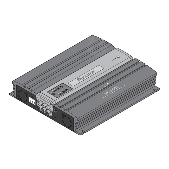
GM-X1024,GM-X924 3 7 63 1515 0 2.2 EXTERIOR L 13942296513 u163 Fig. 2 http://www.xiaoyu163.com... -
Page 5: Te L 13942296513
GM-X1024,GM-X924 3 7 63 1515 0 (1) EXTERIOR SECTION PARTS LIST Mark No. Description Part No. Mark No. Description Part No. 1 Screw(M3×25) HBA0013 46 Cord(CN502) HDE5501 2 Screw(M3×12) CBA1323 47 Cord(CN552) HDE5501 3 Screw(M3×14) CBA1382 48 Cord(CN854) HDE5501... -
Page 6: Http://Www.xiaoyu163.Com
GM-X1024,GM-X924 3 7 63 1515 0 (2) CONTRAST TABLE GM-X1024/X1R/UC, GM-X924/X1R/UC, GM-X924/X1R/EW and GM-X924/X1R/ES are constructed the same except for the following: Part No. GM-X1024 GM-X924 Mark No. Symbol and Description X1R/UC X1R/UC X1R/EW X1R/ES Heat Sink HNR0073 HNR0093... -
Page 7: Te L 13942296513
GM-X1024,GM-X924 3 7 63 1515 0 L 13942296513 u163 http://www.xiaoyu163.com... -
Page 8: Schematic Diagram
GM-X1024,GM-X924 3 7 63 1515 0 3. SCHEMATIC DIAGRAM 3.1 OVERALL CONNECTION DIAGRAM(GUIDE PAGE) Note: When ordering service parts, be sure to refer to “EXPLODED VIEWS AND PARTS LIST” or “ELECTRICAL PARTS LIST”. Large size SCH diagram S501:LPF/HPF -10dBm -7.7dBm... - Page 9 GM-X1024,GM-X924 3 7 63 1515 0 POWER STAGE OVER CURRENT DETECTOR 20.4dBm L 13942296513 THERMO DETECTOR / PROTECTOR OVER VOLTAGE DETECTOR / PROTECTOR MUTE CONTROL REGULATOR CONTROL 0.1V 3.2V 0.3V 0.2V 14.4V 14.4V 14.2V 0.2V 10.7V u163 14.4V Fig. 3 A E F http://www.xiaoyu163.com...
- Page 10 GM-X1024,GM-X924 3 7 63 1515 0 L 13942296513 u163 http://www.xiaoyu163.com...
- Page 11 GM-X1024,GM-X924 3 7 63 1515 0 L 13942296513 u163 Fig. 4 http://www.xiaoyu163.com...
- Page 12 GM-X1024,GM-X924 3 7 63 1515 0 L 13942296513 u163 http://www.xiaoyu163.com...
- Page 13 GM-X1024,GM-X924 3 7 63 1515 0 L 13942296513 u163 Fig. 5 http://www.xiaoyu163.com...
-
Page 14: Pcb Connection Diagram
GM-X1024,GM-X924 NOTE FOR PCB DIAGRAMS 1. The parts mounted on this PCB include all necessary 3 7 63 1515 0 parts for several destination. For further information for respective destinations, 4. PCB CONNECTION DIAGRAM be sure to check with the schematic diagram. - Page 15 GM-X1024,GM-X924 2. Viewpoint of PCB diagrams 3 7 63 1515 0 Capacitor Connector SIDE A SIDE A SIDE B Chip Part P.C.Board L 13942296513 u163 Fig. 6 http://www.xiaoyu163.com...
- Page 16 GM-X1024,GM-X924 3 7 63 1515 0 4.2 ISO PCB SIDE A L 13942296513 u163 Fig. 7 http://www.xiaoyu163.com...
- Page 17 GM-X1024,GM-X924 3 7 63 1515 0 4.3 A LPF/HPF PCB SIDE A A LPF/HPF PCB CN854 CN503 S501 LPF/HPF FREQUENCY GAIN S501 Fig. 8 L 13942296513 4.4 B LPF/HPF PCB SIDE A B LPF/HPF PCB CN855 CN553 S551 LPF/HPF...
- Page 18 GM-X1024,GM-X924 3 7 63 1515 0 4.5 A P.A. PCB SIDE A A P.A. PCB CN103 Fig. 10 L 13942296513 4.6 B P.A. PCB SIDE A B P.A. PCB CN303 Fig. 11 u163 http://www.xiaoyu163.com...
-
Page 19: Electrical Parts List
GM-X1024,GM-X924 3 7 63 1515 0 5. ELECTRICAL PARTS LIST NOTE: - Parts whose parts numbers are omitted are subject to being not supplied. - The part numbers shown below indicate chip components. Chip Resistor RS1/_S___J,RS1/__S___J Chip Capacitor (except for CQS..) CKS.., CCS.., CSZS.. - Page 20 GM-X1024,GM-X924 3 7 63 1515 0 =====Circuit Symbol and No.===Part Name Part No. =====Circuit Symbol and No.===Part Name Part No. ------ ------------------------------------------ ------------------------- ------ ------------------------------------------ ------------------------- RD1/4PU101J RN1/4PC7501D RD1/4PU471J RD1/2PM471J RD1/4PU472J RD1/4PU223J RD1/4PU621J RD1/4PU103J RD1/4PU561J RD1/4PU332J RD1/4PU333J RN1/4PC1002D RD1/4PU472J...
- Page 21 2SB1243 CCPUSL470J50 Transistor 2SC2458 CCPUSL470J50 Transistor 2SD1864 CCPUSL470J50 Transistor 2SD1919 Transistor 2SD1919 Unit Number : HWH0066(GM-X1024/X1R/UC) Unit Number : HWH0067(GM-X924/X1R/UC) Transistor 2SB1277 Unit Number : HWH0064(GM-X924/X1R/EW) Transistor 2SB1277 Unit Number : HWH0065(GM-X924/X1R/ES) IRFIZ44N Unit Name : Amp Unit IRFIZ44N IRFIZ44N...
- Page 22 GM-X1024,GM-X924 3 7 63 1515 0 =====Circuit Symbol and No.===Part Name Part No. =====Circuit Symbol and No.===Part Name Part No. ------ ------------------------------------------ ------------------------- ------ ------------------------------------------ ------------------------- Diode 1SS133 RD1/4PU102J Diode 1SS133 RD1/4PU390J Diode 1SS133 RD1/4PU221J Diode 1SS133 RD1/4PU821J Diode...
- Page 23 GM-X1024,GM-X924 3 7 63 1515 0 =====Circuit Symbol and No.===Part Name Part No. =====Circuit Symbol and No.===Part Name Part No. ------ ------------------------------------------ ------------------------- ------ ------------------------------------------ ------------------------- RD1/4PU472J RD1/2PM330J RD1/4PU472J See Contrast table RD1/4PU472J RD1/2PM220J RD1/4PU103J RD1/4PU101J RD1/4PU472J CAPACITORS RD1/4PU223J...
- Page 24 CEAS332M35 CEKA471M50 CEAS332M35 CEKA471M50 CEAS332M35 CQPA102J2A CEAS332M35 CFTLA104J50 CFTLA104J50 CONTRAST TABLE of AMP UNIT GM-X1024/X1R/UC, GM-X924/X1R/UC, GM-X924/X1R/EW and GM-X924/X1R/ES are constructed the same except for the following: Part No. Symbol and Description GM-X1024/X1R/UC GM-X924/X1R/UC GM-X924/X1R/EW GM-X924/X1R/ES S901 Switch Not used...
-
Page 25: Adjustment
GM-X1024,GM-X924 3 7 63 1515 0 6. ADJUSTMENT Item Conditions Adjustment point Specifications Idling current Input ; adjust 30 seconds after 1kΩ terminate VR101(A Lch) mV Meter(1) : 20±6mV (adjustment) power is switched on, and within 20 VR201(A Rch) seconds. -
Page 26: General Information
GM-X1024,GM-X924 3 7 63 1515 0 7. GENERAL INFORMATION 7.1 IC PA2027A Transient voltage detector Stby Bandgap DET1 Circuit motion:on DET2 Cont_V 50µA L 13942296513 DET_R Filter 4.7kΩ Bandgap:on Switch:on Vs_out 0.13V Mute_out 5.6V Oneshot (1µsec) u163 http://www.xiaoyu163.com... -
Page 27: Disassembly
GM-X1024,GM-X924 3 7 63 1515 0 7.2 DISASSEMBLY Panel Unit - Removing the Case and the Panel Unit 1. Remove eight screws A, seven screws B and two screws C. 2. Remove Case and Panel Units. Case Panel Unit Fig. -
Page 28: Block Diagram
GM-X1024,GM-X924 3 7 63 1515 0 7.3 BLOCK DIAGRAM L 13942296513 u163 Fig. 15 http://www.xiaoyu163.com... -
Page 29: Operations And Specifications
GM-X1024,GM-X924 3 7 63 1515 0 8. OPERATIONS AND SPECIFICATIONS 8.1 OPERATIONS - GM-X1024/X1R/UC L 13942296513 u163 http://www.xiaoyu163.com... - Page 30 GM-X1024,GM-X924 3 7 63 1515 0 L 13942296513 u163 http://www.xiaoyu163.com...
- Page 31 GM-X1024,GM-X924 3 7 63 1515 0 - GM-X924/X1R/EW L 13942296513 u163 http://www.xiaoyu163.com...
- Page 32 GM-X1024,GM-X924 3 7 63 1515 0 L 13942296513 u163 http://www.xiaoyu163.com...
- Page 33 GM-X1024,GM-X924 3 7 63 1515 0 8.2 SPECIFICATIONS L 13942296513 u163 http://www.xiaoyu163.com...
Need help?
Do you have a question about the GM-X1024 and is the answer not in the manual?
Questions and answers