Table of Contents
Advertisement
Advertisement
Table of Contents
Troubleshooting

Related Manuals for Miller Auto-Axcess 300 CE


Summary of Contents for Miller Auto-Axcess 300 CE
- Page 1 OM-231185Y 2016−04 Processes MIG (GMAW) Welding Pulsed MIG (GMAW-P) Flux Cored (FCAW) Welding Automatic Welding Description Automatic Welding Interface And Arc Welding Power Source Auto-Axcess 300 ™ Visit our website at File: Advanced Manufacturing Systems www.MillerWelds.com/ams...
- Page 2 We know you don’t have time to do it any other way. That’s why when Niels Miller first started building arc welders in 1929, he made sure his products offered long-lasting value and superior quality.
-
Page 3: Table Of Contents
TABLE OF CONTENTS SECTION 1 − SAFETY PRECAUTIONS - READ BEFORE USING ....... . . 1-1. - Page 4 TABLE OF CONTENTS SECTION 7 − MAINTENANCE ..............7-1.
-
Page 5: Declaration Of Conformity
DECLARATION OF CONFORMITY for European Community (CE marked) products. MILLER Electric Mfg. Co., 1635 Spencer Street, Appleton, WI 54914 U.S.A. declares that the product(s) identified in this declaration conform to the essential requirements and provisions of the stated Council Directive(s) and Standard(s). - Page 6 907274 AUTO-AXCESS 450 CE W/INSIGHT CORE 907274006 AUTO-AXCESS 450 CE WITH RMD 907274011 AUTO-AXCESS 300 CE AUTO-LINE ANALOG 907349 AUTO-AXCESS 300 CE AUTO-LINE ANALOG W/INSIGHT CORE 907349006 Compliance Information Summary Applicable regulation Directive 2014/35/EU Reference limits Directive 2013/35/EU, Recommendation 1999/519/EC...
-
Page 7: Section 1 − Safety Precautions - Read Before Using
SECTION 1 − SAFETY PRECAUTIONS - READ BEFORE USING som 2015−09 Protect yourself and others from injury — read, follow, and save these important safety precautions and operating instructions. 1-1. Symbol Usage DANGER! − Indicates a hazardous situation which, if Indicates special instructions. - Page 8 D Remove stick electrode from holder or cut off welding wire at FUMES AND GASES can be hazardous. contact tip when not in use. D Wear body protection made from durable, flame−resistant material Welding produces fumes and gases. Breathing (leather, heavy cotton, wool). Body protection includes oil-free these fumes and gases can be hazardous to your clothing such as leather gloves, heavy shirt, cuffless trousers, high health.
-
Page 9: Additional Symbols For Installation, Operation, And Maintenance
1-3. Additional Symbols For Installation, Operation, And Maintenance FIRE OR EXPLOSION hazard. MOVING PARTS can injure. D Do not install or place unit on, over, or near D Keep away from moving parts such as fans. combustible surfaces. D Keep all doors, panels, covers, and guards D Do not install unit near flammables. -
Page 10: California Proposition 65 Warnings
1-4. California Proposition 65 Warnings Welding or cutting equipment produces fumes or gases This product contains chemicals, including lead, known to which contain chemicals known to the State of California to the state of California to cause cancer, birth defects, or other cause birth defects and, in some cases, cancer. -
Page 11: Section 2 − Consignes De Sécurité − Lire Avant Utilisation
SECTION 2 − CONSIGNES DE SÉCURITÉ − LIRE AVANT UTILISATION fre_som_2015−09 Pour écarter les risques de blessure pour vous−même et pour autrui — lire, appliquer et ranger en lieu sûr ces consignes relatives aux précautions de sécurité et au mode opératoire. 2-1. - Page 12 chauffement ou un incendie. Avant de commencer le soudage, vérifier LES PIÈCES CHAUDES peuvent et s’assurer que l’endroit ne présente pas de danger. provoquer des brûlures. D Déplacer toutes les substances inflammables à une distance de D Ne pas toucher à mains nues les parties chaudes. 10,7 m de l’arc de soudage.
-
Page 13: Dangers Supplémentaires En Relation Avec L'installation, Le Fonctionnement Et La Maintenance
D Tenir les bouteilles éloignées des circuits de soudage ou autres LE BRUIT peut endommager l’ouïe. circuits électriques. D Ne jamais placer une torche de soudage sur une bouteille à gaz. Le bruit des processus et des équipements peut affecter l’ouïe. D Une électrode de soudage ne doit jamais entrer en contact avec D Porter des protections approuvées pour les une bouteille. -
Page 14: Proposition Californienne 65 Avertissements
RAYONNEMENT HAUTE LE SOUDAGE À L’ARC risque de FRÉQUENCE (H.F.) risque provoquer des interférences. provoquer des interférences. D L’énergie électromagnétique risque D Le rayonnement haute fréquence (H.F.) peut provoquer des interférences pour l’équipement provoquer des interférences avec les équi- électronique sensible tel que les ordinateurs et l’équipement commandé... -
Page 15: Section 3 − Definitions
SECTION 3 − DEFINITIONS 3-1. Additional Safety Symbols and Definitions Some symbols are found only on CE products. Warning! Watch Out! There are possible hazards as shown by the symbols. Safe1 2012−05 Wear dry insulating gloves. Do not touch electrode with bare hand. Do not wear wet or damaged gloves. Safe2 2012−05 Protect yourself from electric shock by insulating yourself from work and ground. - Page 16 Do not remove or paint over (cover) the label. Safe20 2012−05 When power is applied failed parts can explode or cause other parts to explode. Safe26 2012−05 Flying pieces of parts can cause injury. Always wear a face shield when servicing unit. Safe27 2012−05 Always wear long sleeves and button your collar when servicing unit.
-
Page 17: Miscellaneous Symbols And Definitions
3-2. Miscellaneous Symbols And Definitions Some symbols are found only on CE products. Direct Current Alternating Amperage Voltage (DC) Current (AC) Output Circuit Breaker Remote Positive Negative Voltage Input Protective Earth Arc Force Constant Voltage Inductance (Ground) Three Phase Static Frequency Con- Gas Metal Arc Increase... -
Page 18: Section 4 − Specifications
SECTION 4 − SPECIFICATIONS 4-1. Serial Number And Rating Label Location The serial number and rating information for this product is located on the rear . Use rating label to determine input power requirements and/or rated output. For future reference, write serial number in space provided on back cover of this manual. 4-2. -
Page 19: Duty Cycle And Overheating
4-4. Duty Cycle And Overheating Duty Cycle is percentage of 10 minutes that unit can weld at rated load without overheating. If unit overheats, thermostat(s) opens, output stops, and cooling fan runs. Wait fifteen minutes for unit to cool. Reduce amperage or 3 PHASE duty cycle before welding. -
Page 20: Environmental Specifications
4-6. Environmental Specifications A. IP Rating IP Rating IP21S This equipment is designed for indoor use and is not intended to be used or stored outside. IP21S 2014−06 B. Information On Electromagnetic Compatibility (EMC) This Class A equipment is not intended for use in residential locations where the electrical power is provided by the public low− voltage supply system. -
Page 21: Section 5 − Installation
SECTION 5 − INSTALLATION Appearance of actual unit may vary from unit shown in manual. 5-1. Selecting A Location Do not move or operate unit where it could tip. Movement Location And Airflow Special installation may be required where gasoline or volatile liquids are present −... -
Page 22: Rear Panel Receptacles And Supplementary Protectors
5-3. Rear Panel Receptacles And Supplementary Protectors 115 V 10 A AC Receptacle RC2 Receptacle supplies single-phase power. Maximum output from RC2 is limited by supplementary protector CB1 to 10 amps. Supplementary Protector CB1 Supplementary Protector CB2 CB1 protects 115 volt receptacle RC2 from overload. -
Page 23: Connecting To Weld Terminals
5-4. Connecting To Weld Terminals If using an electrode negative (straight polarity) process, the volt sense lead must be disconnected from the work. Do not place anything between weld cable terminal and copper bar. Correct Installation Incorrect Installation Tools Needed: 19 mm (3/4 in.) Ref. -
Page 24: Weld Output Terminals And Selecting Weld Cable Sizes
( ) = mm for metric use ***For distances longer than those shown in this guide, call a factory applications rep. at 920-735-4505 (Miller) or 1-800-332-3281 (Hobart). Ref. S-0007-L 2015−02 In pulse welding applications using inverter power sources, peak currents can result in extreme voltage drops producing poor welding characteristics with undersized cables. -
Page 25: Peripheral Receptacle Functions
5-7. Peripheral Receptacle Functions Function Socket Socket Information Not used. Not used. Circuit common. Purge Contact closure to C completes 24 volts DC solenoid circuit to purge shielding gas line. Contact closure to F indicates coolant flow switch is closed and recirculating coolant system is Coolant Flow operational. -
Page 26: Electrical Service Guide
5-9. Electrical Service Guide Elec Serv 2014−01 Failure to follow these electrical service guide recommendations could create an electric shock or fire hazard. These recommendations are for a dedicated circuit sized for the rated output and duty cycle of the welding power source. In dedicated circuit installations, the National Electrical Code (NEC) allows the receptacle or conductor rating to be less than the rating of the circuit protection device. - Page 27 Notes OM-231185 Page 21...
-
Page 28: Connecting 3−Phase Input Power
5-10. Connecting 3−Phase Input Power = GND/PE Earth Ground Route input conductors to filter board. Route ground conductor through tubing and current transducer to ground terminal. Tools Needed: 5/16 in. Input5 2013−04 Ref. 803 766-C / 804 750-B / Ref. 803 855-B OM-231185 Page 22... -
Page 29: Touch Sensor Operation
5-10. Connecting 3-Phase Input Power (Continued) Select size and length of conductors using Connect input conductors L1, L2, and L3 to Turn Off welding power source, and Section 5-9. Conductors must comply with welding power source line terminals. check voltage on input capacitors national, state, and local electrical codes. -
Page 30: Section 6 − Operation
SECTION 6 − OPERATION 6-1. Operational Terms The following is a list of terms and their definitions as they apply to this interface unit: General Terms: AccuCurve CV Pulse process using a pulse waveform with modified curves at particular locations within the waveform. Has a distinguished change in arc characteristics. - Page 31 6-1 . Operational Terms (Continued) Time Indicates time values being set for timed functions (e.g. Preflow, Postflow which are only available in the Arc On and Analog input or the Arc On and No Analog input modes). Volts Preset voltage in MIG mode at idle, actual voltage while welding, and 3 seconds hold value at end of weld. Weld Sequence function that allows for a timed weld operation [(0 to 999 seconds) only available on Auto Axcess models in the Arc On and Analog input or the Arc On and No Analog input modes, and can only be set with the...
-
Page 32: Front Panel Controls (See Section 6-3)
6-2. Front Panel Controls (See Section 6-3) Adjust Setup Arc Control When an LED is lit, it means the related function is active. 219 712-A Program Display The lit LED indicates which setup mode is Setup Push Button active. Setup mode parameters are shown in Press button to select Process, Wire Type, Displays the number of the active program. -
Page 33: Front Panel Controls - Continued (See Section 6-2)
6-3. Front Panel Controls - Continued (See Section 6-2) 10 Wire Feed/Gas/Contactor LEDs and while welding unless the the unit is in 14 Volts And Arc Adjust LEDs Display Command Values mode. Only wire The Wirefeed LED lights when the wire feeder The lit LED indicates whether voltage or arc speed command will be displayed while length is being displayed. - Page 34 Table 6-1. Welding Wire And Gas Abbreviations* Wire Description Wire Abbreviation Alloy Type Gas Type Gas Abbreviation Steel E70, E100, E120 100% CO 90% Argon/10% CO 85% Argon/15% CO 75% Argon/25% CO 95% Argon/5% CO 95% Argon /5% O Stainless Steel 308, 309, 312, 316 98% Argon, 2% O (81Ar/18HE/1CO...
-
Page 35: Robot Calibration Mode
6-5. Robot Calibration Mode Use the robot calibration mode to custom-calibrate the power source to the robot command signals. This ensures the wire speed, voltage, and arc adjust are the same on the robot pendant as on the power source. XXXX The factory recommendation is to perform the calibration on all... -
Page 36: Robot Auto-Calibration Sample Programs
6-6. Robot Auto-Calibration Sample Programs It is critical to make certain that NO start power, start conditions, run-in, or crater parameters of any kind are present in the robot program. The welding power source is looking for 2 distinct welding conditions. If there is a “start power” condition, the welding power source will equate this as the first condition and fail to execute Auto-Cal correctly. -
Page 37: Reset Mode
6-7. Reset Mode Reset mode is not active when Program Lock is enabled. The reset mode allows the operator to reload factory program settings for all eight active programs in the unit. System configuration data will be lost during the Reset operation. Setup Adjust Arc Control... -
Page 38: Section 7 − Maintenance
SECTION 7 − MAINTENANCE 7-1. Routine Maintenance Disconnect power Maintain more often before maintaining. during severe conditions. n = Check Z = Change ~ = Clean l = Replace Reference * To be done by Factory Authorized Service Agent Every l Unreadable Labels ~ Weld Terminals l Damaged Gas Hose... -
Page 39: Section 8 − Safety Precautions For Servicing
SECTION 8 − SAFETY PRECAUTIONS FOR SERVICING Protect yourself and others from injury — read, follow, and save these important safety precautions and operating instructions. 8-1. Symbol Usage safety_stm 2015-09 DANGER! − Indicates a hazardous situation which, if Indicates special instructions. not avoided, will result in death or serious injury. -
Page 40: California Proposition 65 Warnings
OVERUSE can cause OVERHEATING. FALLING EQUIPMENT can injure. D Allow cooling period; follow rated duty cycle. D Use lifting eye to lift unit only, NOT running gear, gas cylinders, or any other accessories. D Reduce current or reduce duty cycle before starting to weld again. -
Page 41: Section 9 − Troubleshooting
SECTION 9 − TROUBLESHOOTING 9-1. Set Value Mode Setup Adjust Arc Control 219 712-A The Set Value mode is a troubleshooting tool Enter the Set Value mode by pressing the changed in the bottom display. Press the Wire that allows certain robot command values to Setup and Arc Control push buttons at the Feed Speed/Amps push button to toggle be manually over-ridden. -
Page 42: Error Code Troubleshooting Tables
9-2. Error Code Troubleshooting Tables Display Example TACH The following error codes may appear on the upper and lower displays of the User Interface Module to indicate specific errors. Explanations of the error codes are provided in the sections referenced. User Interface Module User Interface Module Error Type... - Page 43 Emergency Stop Error Indicates an emergency stop error. Receptacle RC5-1 connects to receptacle RC1-4 and receptacle RC5-2 connects to receptacle RC4-2 on E-Stop board PC12. A closure between RC4-1 and RC4-2 allows +24 volts DC to be supplied to the four relays on E-Stop board PC12. In an E-Stop situation (relays open), all four relays on the E-Stop board de-energize and cut power to the control boards.
- Page 44 No Tach Error Indicates loss of tachometer feedback. Determine cause of error as follows: Press JOG button on the front panel. Does the motor run wide open immediately? YES ³ Replace Motor Board PC6. Does the motor ramp up in speed? YES ³...
- Page 45 Motor Communications Error The motor board has lost communication with the PCM board PC4. Check cabling and cable routing for boom system motor cable and secondary cables. Separate cable as much as possible. Check if WFM board PC6 code is installed and if microprocessor is running. Check LED3 and LED4 on WFM board PC6. Depending on the wire feed speed, check for 0-40 volts DC on J17-3 to J17-1.
- Page 46 Over Current Error Indicates one or more of the inverter engines has latched with an over-current. Signal is sent from engine module(s) (RC6, Pin 11, on inverter control board PC1) to process control module PC4 (J2, Pin 6). The over-current circuit monitors the inverter high frequency transformer primary current. Normal welding will never trip this circuit, only a fault will cause an over-current condition.
- Page 47 Weld Wait Error WELD Indicates unit was not ready for a weld sequence. Press Jog/Purge button to clear error. WAIT Please Wait Error Indicates user interface board lost data communications. Press Jog/Purge button to clear error. If condition persists, con- tact nearest Factory Authorized Service gent.
- Page 48 AB. Network Wait Indicates that the UIM board PC7 is no longer communicating with the PCM board PC4 by DeviceNet. WAIT AC. Cycle Power CYCL Request to cycle power from the welding power source. Turn unit power off and back on again. AD.
-
Page 49: Removing Cover And Measuring Input Capacitor Voltage
9-3. Removing Cover and Measuring Input Capacitor Voltage Turn Off welding power source, and disconnect in- put power. Significant DC voltage can Tools Needed: remain on capacitors after unit is Off. Always check the voltage as shown to be sure 8mm (5/16 in.) the input capacitors have discharged before working... -
Page 50: Process Control Module Pc4 Diagnostic Leds
9-4. Process Control Module PC4 Diagnostic LEDs Process Control Module PC4 Diagnostic LEDs are visible inside unit, located on PC4 mounted on the top tray. Refer to Section 9-5 for information on diagnostic LEDs. Reinstall cover after checking diagnostic LEDs. LED1 LED2 LED3... -
Page 51: Wire Feed Module Pc6 Diagnostic Leds And Dip Switch Settings
9-6. Wire Feed Module PC6 Diagnostic LEDs And Dip Switch Settings Wire Feed Module PC6 Diagnostic LEDs are visible inside unit, located on PC6 mounted on the top tray assembly. Refer to Section 9-7 for information on diagnostic LEDs. Reinstall top cover after checking diagnostic LEDs. -
Page 52: User Interface Module Pc7 Diagnostic Leds
9-8. User Interface Module PC7 Diagnostic LEDs LED1 LED2 218 559-A / 804 756-B User Interface Module PC7 Reinstall cover after checking diagnostic Dip switches are used to identify each circuit board on the internal network. Dip LEDs. Diagnostic LEDs are visible inside unit, switch settings are different for each circuit located on PC7 mounted behind the front board. -
Page 53: Automation Interface Module Pc9 Diagnostic Leds
9-10. Automation Interface Module PC9 Diagnostic LEDs LED11 LED13 LED25 LED28 LED12 LED14 LED27 LED31 LED30 LED1 LED2 LED3 LED4 LED5 LED6 LED7 LED8 LED9 LED10 LED32 LED33 LED15 LED20 LED19 LED18 LED16 LED21 LED22 LED23 LED24 LED26 LED29 LED17 216 958-A / Ref. -
Page 54: Diagnostic Leds On Automation Interface Module Pc9
9-11. Diagnostic LEDs On Automation Interface Module PC9 Status Diagnosis Input signal On from robot for jog advance. Input signal Off from robot for no jog advance. Input signal On from robot to energize contactor. Input signal Off from robot to not energize contactor. Input signal On remote program A selected. -
Page 55: Network And Module Status Leds
9-11. Diagnostic LEDs On Automation Interface Module PC9 (Continued) Status Diagnosis Input signal On from relay K4 to indicated wire stuck in weld joint. Input signal Off from relay K4 to indicate wire is not stuck in weld joint. Indicates +5 volts DC is present on automation interface module PC9. Indicates +5 volts DC is not present on automation interface module PC9. -
Page 56: Troubleshooting
9-13. Troubleshooting Trouble Remedy No weld output; completely inoperative Place line disconnect in On position (see Section 5-10). Check and replace line fuse(s), if necessary, or reset circuit breaker (see Section 5-10). Check for proper input power connections (see Section 5-10). No weld output;... -
Page 57: Section 10 − Electrical Diagrams
SECTION 10 − ELECTRICAL DIAGRAMS 263 490-B (Part 1 Of 2) Figure 10-1. Circuit Diagram For Welding Power Source (Part 1 Of 2) OM-231185 Page 51... - Page 58 Figure 10-2. Circuit Diagram For Welding Power Source (Part 2 Of 2) OM-231185 Page 52...
- Page 59 RC1 /PLG 263 490-B (Part 2 Of 2) OM-231185 Page 53...
- Page 60 Figure 10-3. Circuit Diagram For 72 Pin Robot Interface OM-231185 Page 54...
- Page 61 219 266-D OM-231185 Page 55...
- Page 62 Figure 10-4. Circuit Diagram For Peripheral/Motor Interface OM-231185 Page 56...
- Page 63 219 267-B OM-231185 Page 57...
-
Page 64: Section 11 − Parts List
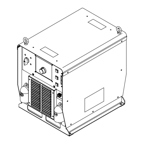
SECTION 11 − PARTS LIST Hardware is common and not available unless listed. 7 − Fig 11-4 5 − Fig 11-3 6 − Fig 11-2 23 − Fig 11-5 804 751-E Figure 11-1. Main Assembly OM-231185 Page 58... - Page 65 Item Dia. Part Mkgs. Description Quantity Figure 11-1. Main Assembly ....+210492 . . . Cover, Top ........... .
- Page 66 Hardware is common and not available unless listed. 20 21 802 955-C Figure 11-2. Windtunnel Assembly LH And RH Item Dia. Part Mkgs. Description Quantity Figure 11-2. Windtunnel Assembly LH And RH (Fig 11-1 Item 6) ....214597 .
- Page 67 Item Dia. Part Mkgs. Description Quantity Figure 11-2. Windtunnel Assembly LH And RH (Continued) (Fig 11-1 Item 5) ... . . 270832 ..Circuit Card Assy, Power Interconnect .
- Page 68 Hardware is common and not available unless listed. 802 916-C Figure 11-3. Top Tray Assembly Item Dia. Part Mkgs. Description Quantity Figure 11-3. Top Tray Assembly (Fig 11-1 Item 5) ..PC12 ..239623 .
- Page 69 Hardware is common and not available unless listed. 803 681-C Figure 11-4. Rear Panel Assembly Item Dia. Part Mkgs. Description Quantity Figure 11-4. Rear Panel Assembly (Fig 11-1 Item 7) ... . . 239600 .
- Page 70 Hardware is common and not available unless listed. 803 682-B Figure 11-5. Front Panel Assembly Item Dia. Part Mkgs. Description Quantity Figure 11-5. Front Panel Assembly (Fig 11-1 Item 22) ....207456 .
- Page 71 Item Dia. Part Mkgs. Description Quantity Figure 11-5. Front Panel Assembly (Fig 11-1 Item 22) (Continued) ....216966 . . . Cover, Connector D-sub 9 pin Male w/Chain .
- Page 72 Notes...
- Page 73 Notes...
- Page 74 Notes...
- Page 75 Effective January 1, 2016 (Equipment with a serial number preface of MG or newer) This limited warranty supersedes all previous Miller warranties and is exclusive with no other guarantees or warranties expressed or implied. Warranty Questions? LIMITED WARRANTY − Subject to the terms and conditions below, 6 Months —...
- Page 76 Contact the Delivering Carrier to: File a claim for loss or damage during shipment. For assistance in filing or settling claims, contact your distributor and/or equipment manufacturer’s Transportation Department. © ORIGINAL INSTRUCTIONS − PRINTED IN USA 2016 Miller Electric Mfg. Co. 2016−01...
Need help?
Do you have a question about the Auto-Axcess 300 CE and is the answer not in the manual?
Questions and answers