Table of Contents
Advertisement
Quick Links
Copyright © 2006
Patton Electronics Company
All Rights Reserved.
USER
MANUAL
MODEL 2702
G.703 Interface Converter
Part# 07M2702-UM
SALES OFFICE
Doc# 08605U2-003
(301) 975-1000
Rev. C
TECHNICAL SUPPORT
Revised 10/26/06
C E R T I F I E D
(301) 975-1007
An ISO-9001
http://www.patton.com
Certified Company
Advertisement
Table of Contents

Summary of Contents for Patton electronics 2702 G.703
- Page 1 Copyright © 2006 Patton Electronics Company All Rights Reserved. USER MANUAL MODEL 2702 G.703 Interface Converter Part# 07M2702-UM SALES OFFICE Doc# 08605U2-003 (301) 975-1000 Rev. C TECHNICAL SUPPORT Revised 10/26/06 C E R T I F I E D (301) 975-1007 An ISO-9001 http://www.patton.com Certified Company...
-
Page 2: Table Of Contents
3.1 DIP Switch Configuration 4.0 Installation ...10 4.1 DTE Interface Connection 4.2 Network Interface Connection 4.3 Power Connection 4.3.1 Using the AC Power Supply (100-240VAC) 4.3.2 Supplying DC Power 4.3.3 Supplying Power via Pin KK 5.0 Operation ...12 5.1 LED Descriptions 5.2 Loop (V.54 &... -
Page 3: Ce And Telecommunication Approvals
1.2 RADIO AND TV INTERFERENCE The Model 2702 generates and uses radio frequency energy, and if not installed and used properly-that is, in strict accordance with the manufacturer's instructions-may cause interference to radio and televi- sion reception. The Model 2702 has been tested and found to comply with the limits for a Class A computing device in accordance with the specifications in Subpart J of Part 15 of FCC rules, which are designed to provide reasonable protection from such interference in a commer-... -
Page 4: Features
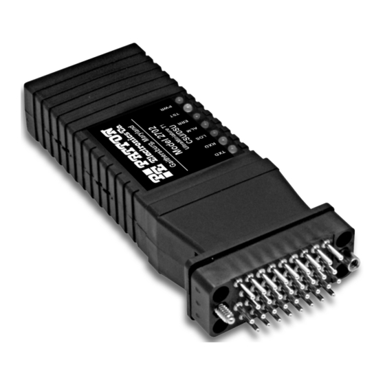
• Easy to Read LEDs for TXD, RSD, ALM, LOTC, TST, and ERR • AMI or HDB3 Line Coding • Configuration via DIP Switches • External 100-240VAC Power Supply 2.2 GENERAL PRODUCT DESCRIPTION The Patton Model 2702 fits into an environment where high-speed E1/G.703 services are being offered to customers with Router/FRADS... -
Page 5: Dip Switch Configuration
3.0 CONFIGURATION The Model 2702 features configuration capability via hardware switches . This section describes all possible hardware switch configu- rations of the Model 2702. 3.1 DIP SWITCH CONFIGURATION The Model 2702 has eight internal DIP switches that allow configu- ration for a wide range of applications. -
Page 6: Dte Interface Connection
Switch SW3 and SW4: Clock Mode SW3 is used to along with SW4 to determine the clock mode. For example the Model 2702 can be set to external clock mode by setting both SW3 and SW4 to the on position. Please refer to the Clock Mode chart below for the desired settings. -
Page 7: Power Connection
240VAC, power supply (center pin is +5V). The universal input power supply is equipped with a male IEC-320 power entry connector. This power supply connects to the Model 2702 by means of a barrel jack on the rear panel. There are a variety of international power cords avail- able for the universal power supply. -
Page 8: Operating Remote Digital Loopback (Rl
LOTC The Loss of Transmit Clock LED lights when the unit detects that there is no transmit clock. The alarm LED indicates the loss of carrier, i.e., no activity on the network. The error LED is not used in Model 2702. The test indicator LED blinks with a specific pattern depending on the type of test mode. -
Page 9: Specifications
APPENDIX A PATTON MODEL 2702 SPECIFICATIONS 2.048 Mbps + 50ppm Network Data Rate: Network Connector: RJ-48C Nominal Impedance: 120 ohm (75 ohm available when using Patton Model 460 Balun) DTE/DCE Interface: V.35 (DCE Orientation) on Male M/34 Line Coding: Selectable AMI or HDB3 Line Framing: G.703 (Unframed) Clocking:... -
Page 10: Factory Replacement Parts And Accessories
Description 2702/CM/UI ...V.35 to E1 Converter (V.35 M/34 Male, 10 - 09F...6 Foot Control Port Cable, 25 mm to DB9F 07M2702 ...User Manual 08055DCUI...Universal Input Power Supply APPENDIX D PATTON MODEL 2702 INTERFACE PIN ASSIGNMENT RJ-48C E1 Network Interface (RJ-48S Female Modular Jack) -
Page 11: Power Supply Interface
DC wall adapter (See Sections 4.3.1 and 4.3.2 above). If you wish to supply power via pin KK on the interface, you must change the setting of the power supply jumper on the printed cir- cuit board. All power sources must be SELV (Circuit, Safety Extra Low Voltage) specified.


Need help?
Do you have a question about the 2702 G.703 and is the answer not in the manual?
Questions and answers