
Related Manuals for Siemens fdsb291


Summary of Contents for Siemens fdsb291
- Page 1 FDSB291 Sounder base Technical manual Building Technologies Fire Safety & Security Products...
- Page 2 Technical specifications and availability subject to change without notice. © 2004-2010 Copyright Siemens Industry, Inc. We reserve all rights in this document and in the subject thereof. By acceptance of the document the recipient acknowledges these rights and undertakes not to publish the document nor the subject thereof in full or in part, nor to make them available to any third party without our...
-
Page 3: Table Of Contents
Table of contents About this document ..................5 Safety......................9 Safety notices....................9 Safety regulations for the method of operation ..........11 Standards and directives complied with............13 Release Notes....................13 Setup and function..................14 Setup ......................14 3.1.1 Details for ordering ................14 3.1.2 Product version ES ................15 Function......................16 3.2.1 Activation levels and sound intensity..........16... - Page 4 Building Technologies 007025_i_en_-- Fire Safety & Security Products 07.05.2010...
-
Page 5: About This Document
About this document About this document Goal and purpose This document contains all necessary information on the FDSB291 sounder base. Consistent compliance with the instructions guarantees correct and safe use. Target groups The information in this document is intended for the following target groups:... - Page 6 About this document Document identification Position Information Title page Product type Product designation Document type Footers Document ID ID_ModificationIndex_Language_COUNTRY – Edition date Last page Document ID Edition date Manual (product line) Register (table of contents for whole documentation, folder register) ...
- Page 7 About this document Applicable documents Document ID Title 008114 Installation of sounder base FDSB291, FDSB292 007227 Operation of detector exchanger and tester FDUD292 009718 Operation of intelligent detector tester FDUD293 007004 Technical manual for automatic fire detectors FDOOT241-9, FDOOT241-8, FDOOT221, FDO241, FDO221, FDT241,...
- Page 8 Sound intensities changed in the Technical data annex 12.2009 Editorial changes made. 07.2009 Editorial changes made, FDSB291 is compatible with heat detector FDT2x1, Technical data annex added 10.2007 Air humidity changed, display texts for detector exchanger and tester added in 'Diagnosis levels' chapter, automatic detection of sounder base as of product version ≥...
-
Page 9: Safety
Safety Safety Safety notices The safety notices must be observed in order to protect people and property. The safety notices in this document contain the following elements: Symbol for danger Signal word Nature and origin of the danger ... - Page 10 Safety Signal word The signal word classifies the danger as defined in the following table: Signal word Danger level DANGER DANGER identifies a dangerous situation, which will result directly in death or serious injury if you do not avoid this situation.
-
Page 11: Safety Regulations For The Method Of Operation
Safety regulations for the method of operation National standards, regulations and legislation Siemens products are developed and produced in compliance with the relevant European and international safety standards. Should additional national or local safety standards or legislation concerning the planning, assembly, installation,... - Page 12 Disregard of the safety regulations Before they are delivered, Siemens products are tested to ensure they function correctly when used properly. Siemens disclaims all liability for damage or injuries caused by the incorrect application of the instructions or the disregard of danger warnings contained in the documentation.
-
Page 13: Standards And Directives Complied With
We are grateful for any suggestions for improvement. Standards and directives complied with A list of the standards and directives complied with is available from your Siemens contact. Release Notes Limitations to the configuration or use of devices in a fire detection installation with a particular firmware version are possible. -
Page 14: Setup And Function
Setup and function Setup and function Setup The sounder base FDSB291 serves to provide an acoustic alarm in an addressed fire detection system FS20. The loud sound of the sounder base can be clearly heard as a danger signal when a fire alarm sounds. -
Page 15: Product Version Es
Setup and function 3.1.2 Product version ES The product version ES provides the technical status of a device in terms of software and hardware. The product version is provided as a two-digit number. The details of your device's product version can be found: On the packaging label ... -
Page 16: Function
FDUD293, a quiet test sound can be activated. A function test is only possible if a point detector is inserted in the sounder base FDSB291. Base sounders with product version ≥30, which are operated on point detectors with product version ≥30, are synchronized to alarm sounders (product version ≥30... -
Page 17: Diagnosis Levels
Setup and function 3.2.4 Diagnosis levels The FDSB291 sounder base monitors its operation largely autonomously. The following diagnosis levels are derived from the different control measurements: Normal Observe information Fault For details, see table below. When a fatal error occurs, which impairs the proper function of the sounder base, a fault message is signaled. -
Page 18: Behaviour In Degraded Mode
Setup and function 3.2.5 Behaviour in degraded mode Applicable for the FDnet: If the main processor of the fire control panel fails, the control panel enters degraded mode operation. Depending on the control panel, the fire control panel may continue to provide the main alarming functions and signaling functions in degraded mode operation. -
Page 19: Connection Terminal Dbz1190-Ab
Setup and function 3.3.3 Connection terminal DBZ1190-AB Auxiliary terminal for connecting cables For T-branches of additional cabling for cable shielding, detector heating units, sounder base, external alarm indicators, etc. For wire diameters of 1 … 2.5 mm 3-pin ... -
Page 20: Project Planning
No direct interface to detector exchanger and tester FDUD292 and to intelligent detector tester FDUD293. A function test of the sounder base FDSB291 with a detector exchanger and tester FDUD292 or an intelligent detector tester FDUD293 is only possible if a point detector is inserted in the sounder base FDSB291. -
Page 21: Mounting / Installation
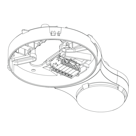
Mounting / Installation Mounting / Installation Assembly The sounder base is fitted directly on the ceiling. The recess-mounted cable entry or surface-mounted cable entry is as for a standard detector base. 1. Insert cables. 2. Use two screws to secure sounder base to ceiling. Ensure that the cables aren't pinched. -
Page 22: Electric Connection
Mounting / Installation Electric connection Note the positive and negative connections. Only connect one wire per terminal. This is the only way of ensuring a problem- free connection over the device's entire service life. You will need at least one auxiliary terminal to connect the base sounder. Two ... - Page 23 Mounting / Installation Procedure 1. Connect sounder base as shown in connection diagram. 2. Press the wires flat into the sounder base so they don't get pinched when installing the point detector. Connection diagram FDB2xx FDSB29x LINE Connection for sounder base 1 Control panel 6 Alarm indicator 2 Sounder base...
-
Page 24: Designation Plate Fdbz291
Mounting / Installation Designation plate FDBZ291 1. Label designation plate FDBZ291 with location address of point detector or alarm sounder. 2. Note the small mark on the installed point detector or alarm sounder and slide designation plate into detector base or sounder base. Installation of designation plate FDBZ291 1 Designation plate FDBZ291 3 Marks on point detector/alarm... -
Page 25: Commissioning
Operating the sounder base on a collective detector line prevents alarms and faults from being recorded and processed. Fire may spread unhindered. Do not use the sounder base FDSB291 on a collective detector line. The device is commissioned via the control panel. The exact procedure is described in the control panel documentation. -
Page 26: Configuration
Configuration Configuration The following chapters contain the specifications of the different tones. The specifications differ for sounder bases with product version <30 and product version ≥30. Sounder base with product version <30 Tone Frequency Pulse pattern Adjustable sound Norm pattern intensity levels (typ. -
Page 27: Sounder Base With Product Version ≥30
Configuration Tone Frequency Pulse pattern Adjustable sound Norm pattern intensity levels (typ. values in [dBA/1 m] Sweep from → to 12 V 32 V Alternating 560 Hz 'French fire sound' 440 Hz NF S 32-001 -1975 Intermittent 420 Hz Australia 'Alert' AS 2220 -1978 Slow-whoop 500 Hz →... - Page 28 Configuration Tone Frequency Pulse pattern Adjustable sound intensity Norm pattern levels (typ. values in [dBA/1 Sweep from → 12 V 32 V Slow-whoop 500 Hz → NEN 2575 1200 Hz Sweep-up, (Netherlands) linear Pulse tone 500 Hz Swedish Standard SS 03 17 11, No. 1 'Imminent Danger' Intermittent 500 Hz...
-
Page 29: Maintenance / Repair
Maintenance / Repair Status retrieval The FDSB291 sounder base has a proximity interface (MC link). Using this interface, it is possible to read out data from the device in a proximity method over short distances with the detector exchanger and tester FDUD292 or the intelligent detector tester FDUD293. -
Page 30: Specifications
Specifications Specifications Technical data Detector line Operating voltage 12 … 33 VDC Operating current: Quiescent condition 150 μA Sound activated 1.2 mA Maximum current connection factor Quiescent current connection factor Address connection factor Separator connector factor Protocol FDnet Compatibility See 'List of compatibility' External alarm indicators... -
Page 31: Dimensions
Standards Standards EN 54-3 VdS approvals G204062 Certificates 0786-CPD-20013 CE conformity mark Protection categories IEC 60529 QA Standards Siemens Standard SN 36350 ISO 9001 ISO 9004 Dimensions 153 mm Sounder base dimensions Environmental compatibility Reusable materials ... -
Page 32: Annex Technical Data
Annex technical data Annex technical data 10.1 Tones and sound intensities of the alarm sounder (32 VDC) Sound intensity measured in dBA/1 m with -0/+4 dBA (32 VDC) Tone No. 1: Continuous Sound Horizontal Vertical intensity 15° 45° 75° 105° 135°... - Page 33 Annex technical data Tone No. 5: Pulse tone Sound Horizontal Vertical intensity 15° 45° 75° 105° 135° 165° 15° 45° 75° 105° 135° 165° 0 (max.) 1 (low) Tone No. 6: Intermittent Sound Horizontal Vertical intensity 15° 45° 75° 105° 135°...
- Page 34 Annex technical data Tone No. 10: Slow-whoop Sweep-up, linear Sound Horizontal Vertical intensity 15° 45° 75° 105° 135° 165° 15° 45° 75° 105° 135° 165° 0 (max.) 1 (low) Tone No. 11: Intermittent Sound Horizontal Vertical intensity 15° 45° 75° 105°...
-
Page 35: Index
Index Index Base sounder Intelligent detector tester FDUD293, 17, 20 Connection, 22 MC link, 16, 29 Interface MC link, 29 Cable entry, 21 Collective detector line, 20 Compatibility, 20 Line separator Collective detector line, 20 Function, 16 Detector, 14 List of compatibility, 7, 18, 20 Detector exchanger and tester FDUD292, 20 Detector heating unit FDBH291, 20 Maintenance intervals, 29... - Page 36 Issued by © 2004-2010 Copyright Siemens Industry, Inc. Siemens Switzerland Ltd Technical specifications and availability subject to change without notice. Industry Sector Building Technologies Division International Headquarters Gubelstrasse 22 CH-6301 Zug Tel. +41 41-724 24 24 www.siemens.com/buildingtechnologies Document ID 007025_i_en_--...