
Related Manuals for Patton electronics Kilo-Link 2073


Summary of Contents for Patton electronics Kilo-Link 2073
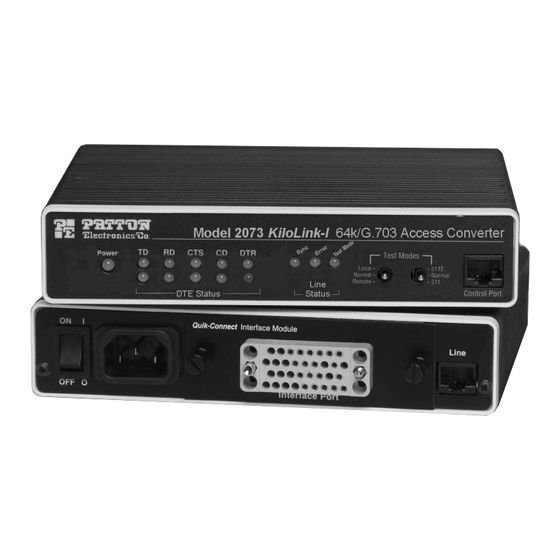
- Page 1 Kilo-Link™ 64k/G.703 Access Converter/Rate Adapter Part# 07M2073-A SALES OFFICE Doc# 0311091UA (301)975-1000 Revised 12/4/99 TECHNICAL SUPPORT (301)975-1007 An ISO-9001 http://www.patton.com Certified Company...
-
Page 2: Radio And Tv Interference
However, there is no guarantee that interfer- ence will not occur in a particular installation. If the Model 2073 does cause interference to radio or television reception, which can be deter-... - Page 3 Patton Electronics' technical staff is also available to answer any questions that might arise concerning the installation or use of your Model 2073. Technical Service hours: 8AM to 5PM EST, Monday through Friday. Thank you for your purchase of this Patton Electronics product.
-
Page 4: Configuring The Hardware Dip Switches
Timing Mode, the data rate defaults to 128kbps. NOTE 2 : Asynchronous rates are 9600, 14,400, and 19,200. To run in asynchro- nous mode, set the 2073 for 64K synchronous to over sample the data bits. S1 Summary Table Function... - Page 5 Use switch S1-8 to control the reception of the V.54 remote digital loopback preparatory phase bit pattern by the local Model 2073. When this switch is “On”, the local 2073 will respond to any V.54 loopback requests that are received from the G.703 network. This is the normal setting.
- Page 6 4.1 Connecting to a PCM Network Channel The RJ-45 port on a model 2073 is pre-wired for direct connetion to the G.703 PCM network. Connect the RJ-45 port of the Model 2073 to the RJ-45 jack provided by your digital service carrier using a straight through twisted pair cable between 19 and 26 AWG.
-
Page 7: Connecting The Serial Port
The drawing below shows how a QuikConnect™ Module plugs into the back of the Model 2073. Figure 4 below shows how a QuickConnect Module plugs into the back of the Model 2073. -
Page 8: Connecting Power
Reinstall the module according to the instructions in Section 4.2.1. 4.3 CONNECTING POWER The Model 2073 is available with two power supply options: Universal Interface AC Power Supply option (Model 2073-UI) operates in environments ranging from 100 to 253 VAC, with no re- configuration necessary (see Appendix B for available domestic and international power cords). -
Page 9: Test Modes
LED status monitors, and using the built-in loopback test modes. 5.1 POWER-UP To apply power to the Model 2073, first be sure that you have read Section 4.3, and that the unit is connected to the appropriate power source. Then power-up the unit using the rear power switch. - Page 10 (1) to initiate and monitor the tests at the local Model 2073, and (2) to do the same at the remote Model 2073. In this case, the test pattern sent by each Model 2073 will not be looped back, but will be transmitted down the line to the other Model 2073.
- Page 11 PATTON ELECTRONICS MODEL 2073 SPECIFICATIONS Transmission Format: Synchronous/Asynchronous Transmission Line: Four-Wire unconditioned twisted pair Clocking: Internal, external or Network Interface Modules: EIA RS-232/ITU/T V.24, RS-232/530, ITU/T V.35 and ITU/T X.21 Line Rates: 256 kbps DTE Rates Async: 9600, 14400, 19200 kbps...
- Page 12 PATTON ELECTRONICS MODEL 2073 INTERFACE PIN ASSIGNMENT RS-232, RS-530 Interface Pin Description (DB-25 Female Connector) (DCE Configuration) Pin # Signal FG (Frame Ground) TD (Transmit Data) RD (Receive Data) RTS (Request to Send) CTS (Clear to Send) DSR (Data Set Ready)
- Page 13 PATTON ELECTRONICS MODEL 2073 INTERFACE PIN ASSIGNMENT (Continued) X.21 Interface (DB-15 Female Connector) (DTE /DCE Configuration) Pin # Signal 1... . Frame Ground 2... . T (Transmit Data-A) 3.