Table of Contents
Advertisement
Advertisement
Table of Contents

Subscribe to Our Youtube Channel
Related Manuals for Kelvion TEC1

Summary of Contents for Kelvion TEC1
- Page 1 Searle Air Coolers INSTALLATION AND MAINTENANCE INSTRUCTIONS...
- Page 2 Searle Air coolers INSTALLATION & MAINTENANCE INSTRUCTIONS Content : Important Information Health and Safety 2. Warranty Procedure 3. Labelling on Coolers 4. Packaging 5. Loading and Handling 6. Location guidance and Installation Pipework 8. Condensate Drainage & Condensate pump kit options 9.
- Page 3 Health and Safety 1. HEALTH AND SAFETY INSTRUCTION AND SIGNS This concerns the following hazards, which may be encountered when installing and maintaining this equipment: CAUTION All work on the units must be carried out by qualified personnel. Installation and maintenance manual must be kept with unit at all times.
- Page 4 The item may be replaced or rectified if the guarantee claim is valid. For items that have been installed, Kelvion have the right to decide if rectification on site is suitable and who should undertake the work or whether to return / replace the unit(s). For items where Kelvion decides to replace, the original faulty item must be returned.
- Page 5 Labelling 3. LABELLING ON UNITS Labelling on KEC, KME, TEC, DSR, LSR, SM Labelling on FM...
- Page 6 3. LABELLING ON UNITS Kelvion 1. Kelvion logo 2.Searle logo 3. Danger and Caution labels DSR83-3 AL KEC30-4L 44L L1Ph S3G 144Kg 220V - 1Ph - 50hZ 1.04 4 X 25 W 1.12 240V - 1Ph - 50hZ Total AMPS Kelvion 4.
- Page 7 Packaging 4. PACKAGING Please pay attention to following symbols which can be identified on Kelvion packing cartons. Keep dry This way up Fragile Recycle Stacking Wooden crate: • GSL wooden crates incorporate heat treated timber as appropriate aligning with export requirements.
- Page 8 5. LOADING AND HANDLING Appropriate equipment should be used to load, un-load and locate the unit in its operational location. Considera- tion of the products size and weight should be taken ensuring that any equipment (such as fork lifts) meets relevant national standards.
- Page 9 Loading and handling min PL +30 min PL +30 KEC 80/95 KEC 80/95 All large units have recommended points for use when fork or strop lifting, both are clearly marked. Care should be taken to protect the unit against mechanical damage while unloading. Extreme care must be taken to protect coil connections and fins.
- Page 10 LOCATION GUIDANCE AND INSTALLATION Unpacking KEC and KMe Remove the box/crate packaging On most KEC units remove the draintray by removing the four fixings and then fit the hexagonal drain connection and gasket into the hexagonal well inside the draintray. Hand tighten this assembly using the knurled nut on the outside. When the cooler is in position ensure that the drainpan is dropped down into the operating position before tightening its fixings.
- Page 11 Location guidance and installation Unpacking DSR and LSR Remove crate packaging/plastic wrapping On all DSR and LSR units the draintray is already fitted, remove the four fixings securing the unit to the wooden pallet and place into position using the location guidance.
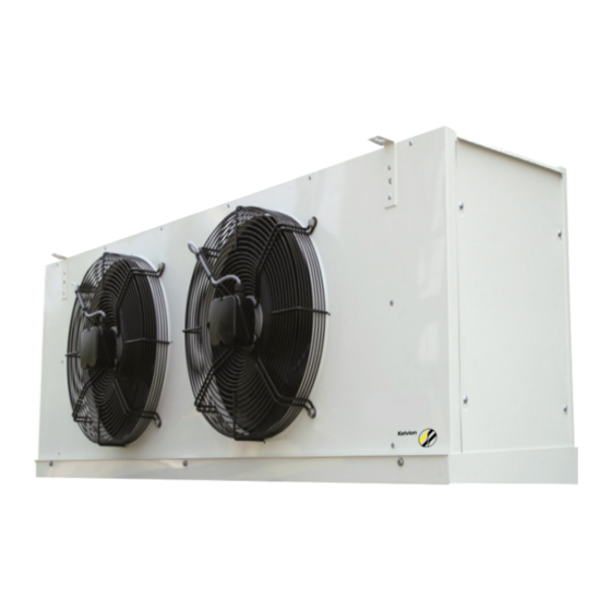
- Page 12 Unpacking SM Remove plastic wrapping On all SM units the draintray is already fitted, remove the fixings/metel brackets securing the unit to the wooden pallet. Place into position using the location guidance Unpacking TEC Searle Air Cooler...
- Page 13 Location guidance and installation The location of the unit should be carefully selected to ensure that: Air distribution from the cooler is not adversely affected by obstructions and is appropriate for the size and shape of the room, optimum air distribution should be targeted. Product loading must be in accordance with good refrigeration practice.
- Page 14 Mounting the unit Warning In case of improper installation, leak of working fluid can occur during operation of the cooling equipment, this can lead to injuries or damage to yourself or property. On all coolers mounting slots are provided, make sure the location guide is observed before you hang the unit Only fix the unit using the mounting slots provided (refer to unit dimension drawings for slot measure- ments)
- Page 15 Installation and Location guidance Mounting a TEC TEC’s that are wall mounted an additional drainpan needs to be fixed to the cooler (a kit is available separately). This is achieved by removing the panel fixing screws around three sides of the air-off face, offering up the verti- cal drainpan and replacing the screws through the holes in the drainpan, securing it in place.
- Page 16 7. PIPEWORK Pipework to and from the cooler should be suitable for: • Working fluid (guidance can be provided by Kelvion representative or pipe suppler) • Atmospheric conditions • Maximum operating pressure including relevant safety factor Damage caused by incorrect installation will invalidate the manufacturer’s warranty obligations.
- Page 17 Condensate drainage 8. CONDENSATE DRAINAGE & CONDENSATE PUMP KIT OPTIONS In most cooler units once the unit is in place the drain tray MUST slope downwards towards the drain connection. Ensure that drainline size is equivalent to that of the drain connection and that it has an adequate fall. It is essential that the drain- line includes a trap, fitted outside the coldroom.
- Page 18 1.0 bar On models TEC1, TEC2 and TEC3 an internally equalised TEV may be used. On units TEC3.5 to TEC8 an externally equalised TEV must be used and an allowance of 1 bar for R134A and 1.5 bar for R404A, R407C, R410A and R507A should be made for the pressure drop across the distribution system.
- Page 19 Dual Orifice 11. DUAL ORIFICE The interchangeable Orifice Distributor is an improvement on the standard flange mounted type in that: • Each distributor is fitted with a dual orifice assembly. • Each distributor has a screwed cap to facilitate orifice selection. •...
- Page 20 To establish the pressure drop, pump the system down and fit a service gauge to the 1/4” flare connection on the distributor cap. Restart the system. The difference between the pressure at at the distributor and the suction pressure is effectively the ‘pressure drop’...
- Page 21 Dual Orifice Schraeder valve c/w Distributor cap Gasket joint 264-475-70 (512E3) 264-475-80(512E4) Nozzle assembly Distributor body inlet connection 12. EVACUATION Fluid coolers using water or water-based solutions must be protected by adding anti-freeze in sufficient concentration, as it is not possible to drain the system completely. Note: The heat transfer properties of a fluid vary with the concentration of additives.
- Page 22 Kelvion would recommend as general rule that each cable or group of cables will be supported at no greater than 500mm intervals; but if national legislation recommends otherwise this should be followed. Cable size is determined by the motor current, with the necessary duration for unit operating temperature.
- Page 23 Wiring diagrams 14. WIRING DIAGRAMS Wiring diagrams for KEC, KECX, KECP KEC 10, 15 & 20 (Fan & Defrost) Note: Supply 230V - 1PH - 50Hz. Applies To KEC Range Only: • KEC 10 - Standard • KEC 15 - Standard •...
- Page 24 KEC 35 & 55 (Fan & Defrost) Note: Fans Supply 230V - 1Ph - 50Hz. Applies to KEC range only • KEC 35 - Standard • KEC 45 - Special High Speed: Connect Supply To Terminal Block Terminals 1 and N. Low Speed: Link Terminal Block Terminals 1 &...
- Page 25 Wiring diagrams Wiring diagrams for KME, KMCX, KMCP 271-111-171 KME 50-95 (DEFROST HEATERS) Note: Defrost Heater Supply 400V - 3Ph - 50Hz. Applies To KME Range Only. • KME 50-95 For Fan Arrangement - Ref. Drg. 271-111-125. Terminal Box(S): 290-660-W; 290- 661-W. KME 50-175 (1 PHASE FAN SUPPLY) Note: Fan Supply 230V - 1Ph - 50Hz.
- Page 26 271-111-172 KME 115-175 (DEFROST HEATERS) Note: Defrost Heater Supply 400V - 3Ph - 50Hz. Applies To KMe Range Only. • KME 115-175 For Fan Arrangement - Ref. Drg. 271-111-125. Terminal Box(S): 290-660-W; 290-661-W. 271-111-125 KMe50-175 (3 PHASE FAN SUPPLY) Note: Fan Supply 400V - 3Ph - 50Hz.
- Page 27 Wiring diagrams Wiring diagrams for TEC, TECX, TECP 271-111-450 TEC (1 PHASE FAN SUPPLY) Note: Fan Supply 230V - 1Ph - 50Hz. Applies To TEC Range Only. • TEC 1-3.5 1 Fan. • TEC 4-5 2 Fans • TEC 7 & 8 3 Fans For Heater Arrangement: •...
- Page 28 Wiring diagrams for DSR DSR 19 & 22 (FAN SUPPLY) Note: Supply 230V - 1Ph - 50Hz. Applies To DSR Range Only: • DSR 19, DSR 22 High Speed: Connect Supply To Terminal Block Terminals 2 And N. Low Speed: Link Terminal Block Terminals 1 & 2. 271-113-405 Terminal Box: 210-604-W DSR 19 &...
- Page 29 Wiring diagrams DSR 36 to 83 (DEFROST HEATERS) Note: Supply 230V - 1Ph - 50Hz. Applies To DSR Range Only: • DSR36 To 83 Heater Option: Remove Link Before Connecting 2nd Phase Supply. 271-113-403 For Fan Arrangement, Ref. Drg. 271-113-401. Terminal Box: 210-609-W.
- Page 30 Wiring diagrams for SM SM 16 to 30 (1 & 2 FAN SUPPLY) Note: Fan supply 400v - 3ph - 50hz. Applies to SM range 1&2 fan only. Fan junction box. For heater arrangement: • REF. DRG. 271-112-215 or/ • REF.
- Page 31 Wiring diagrams Wiring diagrams for FM FM 20 to 36 (2 SPEED FAN) Note: Fan supply 400v - 3ph - 50hz. Applies to FM range only. 2 Speed option only. For heater arrangement: • Ref. Drg. 271-112-211 or/ • Ref. Drg. 271-112-215.LV (As applicable).
- Page 32 FM 20 to 36 (DEFROST DELTA) Note: Defrost heater supply 400v - 3ph-50Hz. Applies to FM range only For clarity multiple defrost heaters not shown. For fan arrangement ref. Drg 271-112-210 And 271-112-211. Terminal box(s): 21-000-623(L1&L2); 23-000-624(L3). For peripheral heater Arrangement ref.
- Page 33 Wiring diagrams Wiring diagrams for LSR LSR 12n (DEFROST WIRING) Note: Defrost heater supply 400v - 3ph -50Hz. Applies to LSR range only For clarity multiple defrost Heaters not shown. For fan arrangement ref. Drg 271-115-173-F. Terminal box: 290-668-w or 431-010-124 271-115-173-E LSR 12n (FAN SUPPLY) Note:...
- Page 34 15. DEFROST Air cooling evaporators whose surface temperature is lower than the dew point of the air they are cooling will accumulate moisture from the air. When the surface temperature is below freezing, this moisture will be deposited in the form of frost and eventually, if left, will restrict heat transfer and air flow.
- Page 35 Coil heathers Time/Pressure termination system All cooler units Reverse cycle/hot gas defrost Pressure equivalent to 25°C SST of the system refrigerant Defrost Termination If a defrost termination thermostat is to be fitted then the normal starting position of the defrost probe is 1/3rd of the way along the coil face (air on) and about 2/3rds up away from any heater elements.
- Page 36 18. MAINTENANCE WARNING! The Unit must be Electrically Isolated before certain Maintenance Work is undertaken. Appropriate PPE should be worn when performing maintenance procedures, adhering to specific site requirements as ap- propriate. Any repairs to the condensers or dry cooler should be undertaken by suitably qualified personnel and relevant national regulations should be adhered to, specifically with regards to handling of working fluids and brazing.
- Page 37 21. INVALIDATION OF GUARANTEE Kelvion accepts no liability according to Kelvion’s terms and conditions of sale, or for loss or damage arising as a result of: Failure to install set up or put to work any part of the equipment in the manner specified in the Installation and...
- Page 38 TEC drawings and dimensions TEC1 & 2 TEC1 & 2 For TEC1 & 5 & TEC 7 40.8 36.3 TEC3.5 & 4& 2 TEC5 1120 TEC6 TEC7 1528 1120 Mounting Slot For TEC6 & TEC8 R 7,5 TEC8 1528 R 4,0...
- Page 39 Product dimensions KEC drawings and dimensions KEC 10 - 15 KEC 20 - 30 726 O/A length 876 O/A length 700 Casework 850 Casework Heater removal Heater removal 500mm (either end) 600mm (either end) 1“D/Conn 1“D/Conn 427.5 427.5 705 Drain pan 855 Drain pan KEC35 - 45 442 Casework...
- Page 40 KMe drawings and dimensions KME 60 KME 50 KME 80, KME 95 1682 1332 1007 1390 Mounting CTRS 1040 Mounting CTRS 715 Mounting CTRS 503.5 Heater Heater Heater removal removal removal 503.5 667.6 842.5 1010.6 Overall drain pan 1335.6 Overall drain pan 1686 Overall drain pan KME 115, KME 140 446.5...
- Page 41 Product dimensions LSR drawings and dimensions LSR 121 1396 Over splash guard 1080 Overall length 1369 Over hangers 750 Fixing centres 1319 Fixing centres O21.0 4 holes 1.1/2“ drain connection LSR 122 1469 Over open drain pans 1755 Overall length 1425 Fixing centres O21.0 4holes Removable...
- Page 42 FM dimensions - Vertical 1200 Mesh guard fitted 1875 on all coils Air operated damper & Heater crowl extension (defrost removal units) 1000 Min Vertical discharge with spigot attachment 1150 option MNTG CRS 2“ BSP (M) 1575 16mm Drain conn MNTG CRS MTG hole 4425...
- Page 43 Product dimensions 1875 3150 Heater removal Heater 1000 Min removal 2000 Min 1220 1220 2“ BSP (M) 16mm 1575 2“ BSP (M) Drain conn MTG hole MNTG CRS 16mm 1425 1425 Drain conn MTG hole MNTG CRS MNTG CRS 4425 1200 Heater Air operated...
- Page 44 SM drawings and dimensions Heater removal 6x O21 Mounting hole 1000 min MTG CTRS 1775 151.5 1355 MTG CTRS Ceiling MTD Base MTD Aerofoil Prop fan 2“ BSP (M) Base MTD CTRS 1355 15mm base drain conn Base MTD CTRS MTG hole 6x O21 Mounting hole Heater...
- Page 45 Product dimensions Unit height Unit height Unit weight ceiling base Case Fins Cu/Al No. of mounted mounted height spacing Model fans in rows (A) mm (B) mm 161 - 4x 161 - 6x 1141 161 - 8x 201 - 4x 201 - 6x 1173 1344...
- Page 46 www.kelvion.com...
Need help?
Do you have a question about the TEC1 and is the answer not in the manual?
Questions and answers