Table of Contents
Advertisement
AIR CONDITIONER
AC052FBCDEH / AC071FBCDEH
AC052HBCDEH / AC071HBCDEH
AC052FCADEH
AC071FCADEH
AC071FCAPEH
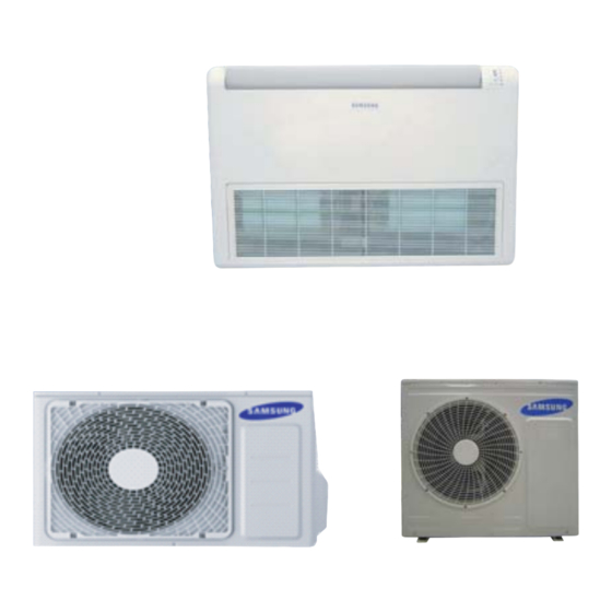
SYSTEM AIR CONDITIONER
Basic : NS052CDXEA/RC052DHXEA
Model : AC052FBCDEH/ AC052FCADEH
AC071FBCDEH/ AC071FCADEH
AC052HBCDEH/ AC052FCADEH
AC071HBCDEH/ AC071FCADEH
Model Code :
AC052FBCDEH/EU AC052FCADEH/EU
AC071FBCDEH/EU AC071FCADEH/EU
AC052HBCDEH/EU AC052FCADEH/EU
AC071HBCDEH/EU AC071FCADEH/EU
CONTENTS
1. Precautions
2. Product Specifications
3. Disassembly and Reassembly
4. Troubleshooting
5. PCB Diagram and Parts List
6. Wiring Diagram
7. Reference Sheet
/ AC071FCAPEH
AC071FCAPEH/EU
Advertisement
Table of Contents

Related Manuals for Samsung NS052CDXEA


Summary of Contents for Samsung NS052CDXEA
- Page 1 SYSTEM AIR CONDITIONER Basic : NS052CDXEA/RC052DHXEA Model : AC052FBCDEH/ AC052FCADEH AC071FBCDEH/ AC071FCADEH / AC071FCAPEH AC052HBCDEH/ AC052FCADEH AC071HBCDEH/ AC071FCADEH Model Code : AC052FBCDEH/EU AC052FCADEH/EU AC071FBCDEH/EU AC071FCADEH/EU AC071FCAPEH/EU AC052HBCDEH/EU AC052FCADEH/EU AC071HBCDEH/EU AC071FCADEH/EU AIR CONDITIONER CONTENTS 1. Precautions 2. Product Specifications 3. Disassembly and Reassembly 4.
-
Page 2: Table Of Contents
Contents 11. Precautions ............................1-1 Installing the air conditioner ......................1-2 Power supply and circuit breaker ....................1-3 During operation ..........................1-4 Disposing of the unit ........................1-5 Others ..............................12. Product Specifications ....................... 2-1 The Feature of Product ........................2-2 Product Specifications ........................ -
Page 3: Installing The Air Conditioner
An all pole disconnection from the power supply must be incorporated in the fixed wiring with a contact opening of >3mm. Do not extend an electric cord to the air conditioner. The air conditioner must be plugged in after you complete the installation. No Tapping and No Extension Cords Samsung Electronics... -
Page 4: During Operation
Never store or load the air conditioner upside down or sideways to prevent the damage to the compressor. Young children or infirm persons should be always supervised when they use the air conditioner. Max current is measured according to IEC standard for safety. Current is measured according to ISO standard for energy efficiency. Samsung Electronics... -
Page 5: Product Specifications
■ Auto Changeover ■ Long Lasting Outdoor Unit Anti Corrosion Cabinet & Heat Exchanger are applied. ■ Free Installation 4 directions piping installation are possible. ■ Various useful functions -Long piping : Max.30m ■ Eco-friendly Product (Lead-Free, RoHS, WEEE) Samsung Electronics... -
Page 6: Product Specifications
Indoor unit Sound Power Outdoor unit Refrigerant(R410A) 1400 1800 1800 Liquid 6.35 6.35 6.35 Connecting Pipe 12.70 15.88 15.88 Additional Refrigerant (R410A) Standard Extension length(Total) Extension length(Elevation) Product 013004-156000-27343C-370010 013007-156000-274750-370010 014077-1560D8-274750-370020 Option Option Code Installation 020000-100000-200000-300000 020000-100000-200000-300000 020000-100000-200000-300000 Option Samsung Electronics... - Page 7 Operation current Heating(STD) 8.80 12.60 Indoor unit Sound Power Outdoor unit Refrigerant(R410A) 1400 1800 Liquid 6.35 6.35 Connecting Pipe 12.70 15.88 Additional Refrigerant (R410A) Standard Extension length(Total) Extension length(Elevation) Product 013064-1950C2-27343C-370010 013064-195591-274750-370010 Option Option Code Installation 020000-100000-200000-300000 020000-100000-200000-300000 Option Samsung Electronics...
-
Page 8: Indoor Unit
2-3 Accessory and Option Specifications Accessories Item Descriptions Code-No. Q'TY Remark Wired remote controller DB97-17846A Owner's Manual DB98-32658A Indoor Unit Installation Manual DB98-32738A PLATE WALL DB61-01351A DB73-20134A RUBBER LEG "071":DB67-20011A DRAIN PLUG Outdoor unit "052":DB67-00477A DB98-34367A INSTALLATION MANUAL Samsung Electronics... - Page 9 3. Disassembly and Reassembly ■ Necessary Tools Item Remark +SCREW DRIVER MONKEY SPANNER Samsung Electronics...
- Page 18 3 10...
-
Page 19: Outdoor Unit
1) loosen 1 pcs screw of cover control,and detach it. 2) loosen 5 pcs screws on both right and left cabniet side edges and to detach the cover-top 3) Loosen 7 screwsfixed to disassemble cabi-front , and detach it. Samsung Electronics 3-11... - Page 20 Parts Procedure Remark common work 4) loosen 7 screws to disassemble the cabi- right ,and detach it. 5) loosen 2 screws to disassemble steel-bar. 6) loosen 3 screws to disassemble cabi-left. 3-12 Samsung Electronics...
- Page 21 Remark fan&motor 1) loosen 1 screw as indication and detached the fan. 2) loosen 4 pcs motor screws and disconnect the wire betwwen assy control out and motor. 3) loosen 2 pcs bracket-motor screw and detach it. Samsung Electronics 3-13...
- Page 22 Heat exchanger 1) Release the refrigerant at first 2) Looosen fixing screw on both side. 3) disaessembly the pipes in both inlet and outlet with welding torch. 4) detach the heat exchanger. 3-14 Samsung Electronics...
- Page 23 Parts Procedure Remark compressor 1) disconnect the compressor lead wire 2)disassembly the felt comp sound. loosen the 3 bolts at the bottom of Samsung Electronics 3-15...
- Page 24 AC071FCADEH / AC071FCAPEH Parts Procedure Remark Common Work 1) Loosen 1 fixing screw of the Cover-Control and detach the Cover Control. 2) Loosen each 7 fixing screws and detach the Cabinet Upper. 3-16 Samsung Electronics...
- Page 25 Parts Procedure Remark 3) Loosen 2 screws fixed to assemble Control Box with Cabinet-Side RH. 4) Loosen fixing screws and detach the Cabinet-Side RH. 5) Loosen 2 screws fixed on the Guide Condenser. Samsung Electronics 3-17...
- Page 26 Parts Procedure Remark 6) Loosen fixing screws of the Cabinet Front. 3-18 Samsung Electronics...
- Page 27 2) Detach the Fan Propeller. 3) Loosen 4 fixing screws to detach the Motor. 4) Disconnect the wire between ASS'Y Control Out and Motor. 5) Loosen 2 fixing bolts and detach the Bracket Motor. Samsung Electronics 3-19...
- Page 28 2) Loosen fixing screw on both sides. 3) Disassemble the pipes in both inlet and outlet with welding torch. 4) Detach the Heat Exchanger. 5) Loosen 4 bolts fixed to assemble Valve Service with Bracket Valve like the picture on the right side. 3-20 Samsung Electronics...
- Page 29 Procedure Remark Compressor 1) Loosen the fixing nut and detach the Compressor Lead Wire. 2) Disassemble the Felt Compressor Sound. 3) Loosen the 3 bolts at the bottom of Compressor like the picture on the right side. Samsung Electronics 3-21...
-
Page 30: Troubleshooting
Indoor’s POWER T/B(open)) Flickering X Off If you turn off the air conditioner when the LED is flickering, the LED is also turned off. If you re-operate the air conditioner, it operates normally at first, then detects an error again. Samsung Electronics... - Page 31 Error regarding special sales taxes E165 Electronic heater discharge temperature protection error E166 Electronic heater windless error E201 Indoor unit number setting error(The outdoor unit informs the error) E422 High pressure blockage error(Refrigerant completely Leakage error) E198 Thermal switch error (open) Samsung Electronics...
-
Page 32: Outdoor Led Error Display And Check Method
PFC Overload Error Check Outdoor Inverter PBA E500 IPM is over heated. Check Outdoor Inverter PBA E554 GAS Leak error Check indoor and outdoor unit model E556 Capacity miss match between indoor and outdoor Check indoor and outdoor unit model Samsung Electronics... -
Page 33: Setting Option Setup Method
SEG 14, 15 SEG 16, 17 SEG 18, 20 SEG 21, 22 SEG23, 24. On(SEG1~12) Off(SEG13~24) SEG1 SEG2 SEG3 SEG4 SEG5 SEG6 SEG7 SEG8 SEG9 SEG10 SEG11 SEG12 SEG13 SEG14 SEG15 SEG16 SEG17 SEG18 SEG19 SEG20 SEG21 SEG22 SEG23 SEG24 Samsung Electronics... - Page 34 11. Setting SEG14, SEG15 option Press Low Fan button( ) to enter SEG14 value. ∨ Press High Fan button( ) to enter SEG15 value. ∧ Each time you press the button, will be selected in rotation. … SEG14 SEG15 Samsung Electronics...
- Page 35 Step 5. Check operation 1. Reset the indoor unit by pressing the RESET button of indoor unit or outdoor unit. 2. Take the batteries out of the remote controller and insert them again and then press the operation button. Samsung Electronics...
- Page 36 Example) If you want to set as "MAIN : 3, CHANNEL : 1, RMC : B", SEG1 SEG2 SEG3 SEG4 SEG5 SEG6 SEG7 SEG8 SEG9 SEG10 SEG11 SEG12 assign option codes except SEG 1, 7 which are page options. Samsung Electronics...
- Page 37 Indication Details Indication Details Indication Details Indication Details Indication Details Indication Details Thermo Disuse Disuse Use of buzzer 1000 Hour Indication ON/OFF Details Control Operation Non use 2000 of buzzer Hour Control Samsung Electronics...
- Page 38 : 2000hr", SEG1 SEG2 SEG3 SEG4 SEG5 SEG6 SEG7 SEG8 SEG9 SEG10 SEG11 SEG12 SEG13 SEG14 SEG15 SEG16 SEG17 SEG18 SEG19 SEG20 SEG21 SEG22 SEG23 SEG24 assign option codes except SEG 1, 7, 13, 19 which are page options. Samsung Electronics...
- Page 39 SEG4 SEG5 SEG6 The option The tens’ digit of The unit digit of The changed Explanation PAGE MODE mode you want an option SEG an option SEG value to change you will change you will change Indication 4-10 Samsung Electronics...
-
Page 40: Items To Be Checked First
The compressor operates in a reverse cycle to remove Indoor fan and outdoor fan stop operation intermittently exterior ice in a HEAT mode, and indoor fan and outdoor in a HEAT mode. fan do not operate intermittently for within 20% of the total heater operation Samsung Electronics 4-11... -
Page 41: Fault Diagnosis By Symptom
Wrong setting Check DIP SW in the Set DIP SW correctly wired remote controller. Correct Is there any error display on Check each item according to error code list the wired remote controller Check the setting temperature 4-12 Samsung Electronics... - Page 42 #1 and #3 Are wire and socket connected correctly? Error 469 display Error 469 display CN05,06,07 TAB terminal(EMI PCB), Check and correct the wiring CN20(INVERTER PCB) (Table No.19) (Table No.19) Check the M/C Samsung Electronics 4-13...
- Page 43 Is the Pin voltage #6 - #3 of CN40 and 41 changed high(4-5V) and low(0-1V) in case of Exchange INVERTER PCB making manual rotation slowly? Is the Pin voltage #7 - #3 of CN40 and Exchange the FAN motor 41 low(0-1V) in normal rotation? Exchange INVERTER PCB 4-14 Samsung Electronics...
- Page 44 Does the compressor rotate normally? Exchange the compressor Are the service valves full opened? Open valve screw to the end. Is AC power voltage normal during the Check AC power source compressor in operation? Exchange INVERTER PCB Samsung Electronics 4-15...
- Page 45 4-WAY valve coil error of 4-WAY valve coil. Dose the voltage of AC220V Exchange apply to the connector of 4-WAY the outdoor PCB. valve coil during the operation? Go to the next page 4-WAY valve main body error 4-16 Samsung Electronics...
- Page 46 Connect the connector. correctly? Check the resistance value Outdoor fan error of outdoor fan. Dose the voltage of DC300V apply to the connector of outdoor Check the motor wire. fan during the operation of outdoor unit? Outdoor PCB error Samsung Electronics 4-17...
-
Page 47: Outdoor Temperature Sensor Error
Exchange the sensor. (Refer to the R/T TABLE) Is the resistance value of sensor connection pull_up 18K? Exchange the PCB. Exchange the PCB. Normal operation Exit 400.0 350.0 300.0 250.0 200.0 150.0 100.0 50.0 4-18 Samsung Electronics... - Page 48 Exchange the sensor. (Refer to the R/T TABLE) Is the resistance value of sensor connection pull_up 24K? Exchange the PCB. Exchange the PCB. Normal operation Exit 600.0 500.0 400.0 300.0 200.0 100.0 Samsung Electronics 4-19...
- Page 49 Exchange the sensor. (Refer to the R/T TABLE) Is the resistance value of sensor connection pull_up 18.2K? Exchange the PCB. Exchange the PCB. Normal operation Exit 400.0 350.0 300.0 250.0 200.0 150.0 100.0 50.0 4-20 Samsung Electronics...
- Page 50 4) Is the resistance value of sensor connection pull_up correct? 2. Troubleshooting procedure Remove the Fan lock. Isn't the Fan locked? Is the connector connected correctly? Connect the connector. Is the color of Fan wire matched correctly? Exchange the Fan. Exchange the PCB. Normal operation Exit Samsung Electronics 4-21...
- Page 51 1) Is the connection of R, S, T power wire normal? 2) Are Relay RY21 and R200 on the INVERTER PCB mounted normally? 2. Troubleshooting procedure Are connection of the wire from INVERTER PBA to Check and correct the wire connection EMI PBA normal? Exchange INVERTER PCB 4-22 Samsung Electronics...
- Page 52 Is insuration resistance between each Exchange the compressor compressor terminal and body normal? Does the compressor rotate normally? Exchange the compressor Did AC power voltage interruption happen Check AC power source during the compressor in operation? Exchange INVERTER PCB Samsung Electronics 4-23...
- Page 53 Is the communication error Terminate the service. occurred again? Isn't the power cable and Correct the wrong wiring. communication cable wiring error? Is the connection of Correct the connection of communication cable normal? communication cable. Exchange the outdoor unit PCB. 4-24 Samsung Electronics...
- Page 54 Exchange the compressor. compressor(u v, v w, w u) normal? Is the compressor body and Exchange the compressor. interphase resistance insulated? Is the connection cable for the Correct the cable connection. compressor and power terminal normal? Exchange the PCB. Samsung Electronics 4-25...
- Page 55 Exchange the compressor. compressor(u v, v w, w u) normal? Is the compressor body and Exchange the compressor. interphase resistance insulated? Is the connection cable for the Correct the cable connection. compressor and power terminal normal? Exchange the PCB. 4-26 Samsung Electronics...
- Page 56 Does the error reappear frequently Exchange INVERTER PCB The cause of this error may be power source trouble as like power interruption. Check the power source. 4-5-16 The others 1. Capacity miss match – Check again the indoor unit option code. Samsung Electronics 4-27...
-
Page 57: Pcb Inspection Method
FAN operation checking 1) Is the FAN motor running? Controller trouble inside of the fan motor Press the ON/OFF button. 2) Is the connection of CN73 normal? connector trouble of CN73 1. FAN Speed[HIGH] 2. FAN mode 4-28 Samsung Electronics... - Page 58 D101 upper side pin of '~' marking pins INVERTER PCB 2) Is DC Link voltage 450-510V? Check IGBT module pins marking voltage near C701 Check BLDC fan 1) See 12-2-3 The Outdoor unit Fan error(Fault Diagnosis) Samsung Electronics 4-29...
-
Page 59: Main Part Inspection Method
BLUE - BLACK 10KΩ ~ 50KΩ pulse ORANGE - BLACK 10KΩ ~ 50KΩ reverse Abnormal 0Ω...Open or Short Outdoor Unit 4way Valve Solenoid Measure resistance with a multimeter Normal At the normal temperature(10˚C~30˚C) 1.6KΩ±15% Abnormal ∞,0Ω...Open or Short 4-30 Samsung Electronics... -
Page 60: Pcb Diagram And Parts List
Panel Louver(stepping motor) SMW250-06(BLU) Micom Program download SMW200-10(BLK) Trans out SMW250-03(RED) Trans In YW396-03V(WHT) AC power YW396-03V(BLU) Drain Pump YW396-03V(YEL) Ventilator YW396-03V(BLK) Fan Tap YW396-09V(BLK) DC12V out(Wired rmote controller power) YW396-02V(WHT) Communication 1(outdoor_ F1/F2) YW396-02V(RED) Communication 2(Wired Remocon_F3/F4) YW396-02V(BLU) Samsung Electronics... - Page 61 Thermistor CN413(WHT) Float Switch CN411(BLK) Drain CN103(YEL) Signal Check CN81(RED) EEPROM CN201(WHT) 4wire communication CN311(WHT) Vent CN804(BLU) Human Sensor CN401(RED) Room Sensor CN412(WHT) CN808(DVM) ( BLU) Louber 5 CN807(BLU) Louber3/4 CN806(BLU) Louber1/2 CN805(WHT) CN801(YEL) Power TB101(BLK) Communication TE04(BLK) Samsung Electronics...
-
Page 62: Display Pcb
#7. TOUCH S/W Out(DC 5V) connector #8. REMOCON SIGNAL Receive #9. GND #10. VCC(DC 5V) AC052HBCDEH/ AC071HBCDEH ① CN01 DISPLAY #1:DC 12V #2~#7:LED Control Signal Output #8:Remocon Signal- Output connecting #9:Auto Switch Signal connector #10:Remocon Signal-Input #11:Ground #12:Vcc #13:No Use Samsung Electronics... - Page 63 #2. GND AC052HBCDEH/ AC071HBCDEH ① CN01-DAMPER S/W CN313-4wire communication (WHT) #1:DC 12V #2:COM2 Control Signal #3:COM2 Check Signal #4: COM2 Check Signal #5:COM2 _Micom _ AD connecting #6:Vcc connector #7: COM2 Enable Signal #8:COM2 #9:COM2 #10:COM2-Write #11:COM2-Read #12:Ground Samsung Electronics...
-
Page 64: Outdoor Pcb Diagram
⑤ DISPLAY CONNECTOR SMW200-10 NTR ⑥ DISPLAY CONNECTOR SMAW250A-03 RED ⑦ PC DOWNLOADCONNECTOR SMW200-10 BLK ⑧ S NE T CONNECTOR SMW200-04 NTR ⑨ AS-PRO DOWNLOAD CONNECTOR SMAW200A-07 WHT ⑩ DISPLAY CONNE CTORS MW200-05 NTR ⑪ DOWNLOAD-INV CONNECTOR S MW200-10 RED Samsung Electronics... - Page 65 ⑥ EEV-A CONNECTOR ⑦ OUT/DIS/COND CONNECTOR SMW250-06 BLU SMAW200-10P BLK ⑧ DOWNLOAD-MAIN CONNECTOR ⑨ CENTRAL-CTL CONNECTOR SMW200-05P WHT YW396-06V WHT ⑩ BLDC-FAN CONNECTOR ⑪ DOWNLOAD-INV CONNECTOR SMAW200-10P RED ⑫ COMP CONNECTOR DBT061-3P WHT DBT081-2P WHT ⑬ REACTOR CONNECTOR Samsung Electronics...
- Page 66 5-2-2 Outdoor Unit PCB SUB PCB : AC071FCADEH/ AC071FCAPEH ① 12V POWER CONNECTOR YW396-02V BLU ② MAIN -SUB SIGNAL CONNECTOT SMW250-04 WHT ③ MAIN -SUB SIGNAL CONNECTOT SMW200-15NTR Samsung Electronics...
- Page 67 SUB PCB : AC052FCADEH ① EVAP THERMISTOR CONNECTOR SMW250-08 WHT ② EEV-B CONNECTOR SMW250-05 YEL ③ DISPLAY-MAIN CONNECTOR SMW200-28 WHT ④ 12V POWER CONNECTOR YW396-02AV BLU Samsung Electronics...
-
Page 68: Wiring Diagram
6. Wiring Diagram 6-1 Indoor Unit AC052FBCDEH/ AC071FBCDEH This Document can not be used without Samsung’s authorization. Samsung Electronics... - Page 69 AC052HBCDEH/ AC071HBCDEH This Document can not be used without Samsung’s authorization. Samsung Electronics...
-
Page 70: Outdoor Unit
6-2 Outdoor Unit Outdoor Unit : AC052FCADEH This Document can not be used without Samsung’s authorization. Samsung Electronics... - Page 71 Outdoor Unit : AC071FCADEH / AC071FCAPEH This Document can not be used without Samsung’s authorization. Samsung Electronics...
-
Page 72: Refrigerating Cycle Diagram
You can open the valve by turning the need valve counterclockwise using hex wrench, and it is used for vacuum, gas purging, coolant injection, coolant purging, and indoor-outdoor unit connection. ■ ACCUMULATOR Accumulator prevents the flow of liquid-state coolant into the compressor. (Liquid-state coolant flowing into the com- pressor will overload the compressor.) Samsung Electronics... -
Page 73: Index For Model Name
Non Inv+Side+Tropical Temp DELUXE FRESH AIR INTAKE STANDARD+ Non Inv+Top+Tropical Temp STANDARD DUCT TROPICAL+MODULE CEILING CONCEILED STANDARD+GENERAL DUCT Temp.+NON MODULE CEILING CONSOLE FLOOR MOUNTING ※ "/" can be removed from the buyer card if there are not enough digits. Samsung Electronics... - Page 74 © Samsung Electronics Co., Ltd.Oct. 2013. This Service Manual is a property of Samsung Electronics Co., Ltd. Printed in China. Any unauthorized use of Manual can be punished under applicable International and/or domestic law. Code No. DB98-32713A(3)
Need help?
Do you have a question about the NS052CDXEA and is the answer not in the manual?
Questions and answers