
Subscribe to Our Youtube Channel
Related Manuals for Futek IPM650

Summary of Contents for Futek IPM650
- Page 1 10 Thomas, Irvine, CA 92618 USA Tel: (949) 465-0900 Fax: (949) 465-0905 IPM650 Product Manual...
-
Page 2: Table Of Contents
Storage ............................. - 5 - Accessories Supplied ........................- 5 - Safety Considerations & Care for Your Device ..................- 5 - Important Information for IPM650......................- 6 - Performance ............................ - 6 - Product Introduction ........................- 6 - Connector &... - Page 3 10 Thomas, Irvine, CA 92618 USA Tel: (949) 465-0900 Fax: (949) 465-0905 6.1.3.9.6 Auto Reset Timer ......................- 50 - 6.1.4 Edit Channel..........................- 51 - 6.1.4.1 Sensor Configuration ......................- 53 - 6.1.4.2 Direction ..........................- 53 - 6.1.4.3 Unit selection ........................
- Page 4 10 Thomas, Irvine, CA 92618 USA Tel: (949) 465-0900 Fax: (949) 465-0905 6.4.3 Alarm Relay 2.......................... - 80 - 6.4.4 Voltage Configuration ......................- 81 - 6.4.5 Current Value.......................... - 82 - 6.4.6 Current Configuration ......................- 83 - Interfaces ............................- 84 - 6.5.1 USB Output ..........................
-
Page 5: Tel: (949)
4 pin connector plug (2) Bumpons (4) Caution FUTEK is not responsible for any damage or injury caused by misuse, misunderstanding, or abuse of this product. 3 Safety Considerations & Care for Your Device Do not disassemble for modifications or repair ... -
Page 6: Important Information For Ipm650
The IPM650 accepts amplified voltage input (±12 VDC), current input (up to 30 mA), and bridge input (up to 500 mV/V), and has the capability to provide power to FUTEK rotary torque sensors (24 VDC/ 1 W and 5 VDC/ 0.05 W). - Page 7 10 Thomas, Irvine, CA 92618 USA Tel: (949) 465-0900 Fax: (949) 465-0905 Built-in shunt calibration features with indicator Lockout feature to prevent inadvertent changes Data logging with up to 21,000 points Supports USB link port Built-in load cell excitation voltage ...
-
Page 8: Connector & Wiring Diagram
10 Thomas, Irvine, CA 92618 USA Tel: (949) 465-0900 Fax: (949) 465-0905 5 Connector & Wiring Diagram Connectors Description Diagram Symbol Description Ground/Shield* Ground/Shield* 1 2 3 4 5 6 7 8 24V OUT 24VDC Output Amplified Input 5V OUT 5VDC Output -V from sensor +V from sensor... -
Page 9: Features
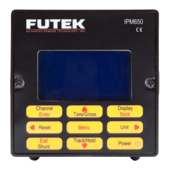
10 Thomas, Irvine, CA 92618 USA Tel: (949) 465-0900 Fax: (949) 465-0905 6 Features 6.1 IPM650 Overview 16x4 Character Peak Value Tracking Value Valley Value Active Channel Number Sampling Rate Channel Information Display Larger Font Navigation Keys Peak/Valley Reset Shunt Calibration... - Page 10 10 Thomas, Irvine, CA 92618 USA Tel: (949) 465-0900 Fax: (949) 465-0905 3.5" 3.5" Screw Terminals Bumpons Tactile Buttons Panel Mount Jacks Black Powder Coated Aluminum Enclosure 6.5" - 10 -...
- Page 11 10 Thomas, Irvine, CA 92618 USA Tel: (949) 465-0900 Fax: (949) 465-0905 Function in Front Panel Button Function in Normal Mode Menu Mode Enter Displays channel information Allows the user to toggle between displaying the tare ▲Arrow and gross values. This can be used to remove any fixture weights.
- Page 12 10 Thomas, Irvine, CA 92618 USA Tel: (949) 465-0900 Fax: (949) 465-0905 Engineering units can only be converted within its own category. Force (Mass): µg, mg, g, kg, M- tone, dyn, kdyn, Mdyn, N, kN, oz, lb, klb, ton (US), ton (UK) Torque: g-mm, g-cm, kg-cm, kg-m, N-mm, N-cm, N-m, KN-m, in-oz, in-lb, ft-lb Pressure:...
-
Page 13: Ipm650 Structure
10 Thomas, Irvine, CA 92618 USA Tel: (949) 465-0900 Fax: (949) 465-0905 6.2 IPM650 Structure TEDS ASCII Output Bridge Input Current Output MCPU Voltage Output Voltage Input Alarm Relay 1 Current Input Alarm Relay 2 Hardware Display Key Pad Controller... -
Page 14: Main Display
10 Thomas, Irvine, CA 92618 USA Tel: (949) 465-0900 Fax: (949) 465-0905 6.3 Main Display FUTEK ADVANCED SENSOR TECH INC. Welcome message will IPM650-PRO be displayed at power on MADE IN USA AUTO CALIBRATION Auto calibration will be applied when device is turned on. - Page 15 10 Thomas, Irvine, CA 92618 USA Tel: (949) 465-0900 Fax: (949) 465-0905 After 10 seconds the following message will be displayed. +2.00001 Peak +2.00000 mV/V +1.99999 Valley 01 Gross - 15 -...
- Page 16 10 Thomas, Irvine, CA 92618 USA Tel: (949) 465-0900 Fax: (949) 465-0905 Pressing the display key will change the reading to a larger font. Pressing it again will switch between modes while still in the large font. The tare and gross modes can also be used while in the larger font mode.
- Page 17 10 Thomas, Irvine, CA 92618 USA Tel: (949) 465-0900 Fax: (949) 465-0905 The shunt key can be pressed any time after the device has been calibrated and a new sensor profile has been loaded. The simulated value is to be used as a calibration reference. SHUNT will blink on the display.
-
Page 18: Main Menu Overview
10 Thomas, Irvine, CA 92618 USA Tel: (949) 465-0900 Fax: (949) 465-0905 7 Main Menu Overview EXIS TING CH(S ) S ENS OR CONFIG FORCE (MAS S ) VIEW CHANNEL DIRECTION TORQUE NEW CHANNEL UNIT S ELECTION PRES S URE EDIT CHANNEL S ENS OR CAPACITY DIS PLACEMENT... - Page 19 10 Thomas, Irvine, CA 92618 USA Tel: (949) 465-0900 Fax: (949) 465-0905 Sensor Profile System setting Data Logging Main Menu Output Config interfaces LCD Setting Lock Setting TEDS Data Diagnostic - 19 -...
- Page 20 10 Thomas, Irvine, CA 92618 USA Tel: (949) 465-0900 Fax: (949) 465-0905 SENSOR PROFILE SYSTEM SETTING ► DATA LOGGING OUTPUT CONFIG INTERFACES LCD SETTING ► LOCK SETTING TEDS DATA LOCK SETTINGS TEDS DATA ► DIAGNOSTIC ------------ Press the MENU key to enter the main menu. Use ▲▼keys to select the desired menu option.
-
Page 21: Sensor Profile
10 Thomas, Irvine, CA 92618 USA Tel: (949) 465-0900 Fax: (949) 465-0905 7.1 Sensor Profile Force Torque Sensor Configuration Pressure ExistingChannel Direction Displacement View Channel Unit Selection mV/V New Channel Sensor capacity Sensor profile Edit Channel Sensitivity (+) Zero Load (+) Save Changes Sensitivity (-) Full Scale (+) -
Page 22: Edit Channel
▲▼ Scroll to “EXISTING CH(S)” using the keys and press ENTER to view the different sensor profiles. The IPM650 is able to store up to 15 different sensor profiles. ► EXISTING CH(S) 01¾ NA VIEW CHANNEL NEW CHANNEL EDIT CHANNEL This function is useful to have a quick view of the number of channels (sensor profile) that have been stored in the internal memory and whether they are active or not. -
Page 23: View Channel
10 Thomas, Irvine, CA 92618 USA Tel: (949) 465-0900 Fax: (949) 465-0905 7.1.2 View Channel Scroll to select “VIEW CHANNEL” form the “SENSOR PROFILE” using the▲▼ keys and press ENTER to view: channel number, sensor type, serial number, capacity and engineering unit. If currently more than one channel exists, pressing the arrow ◄►keys on the keypad will cycle through the existing channels. -
Page 24: Direction
10 Thomas, Irvine, CA 92618 USA Tel: (949) 465-0900 Fax: (949) 465-0905 7.1.3 New Channel Scroll to “NEW CHANNEL” from the “SENSOR PROFILE” using the▲▼ keys and press ENTER. Use ◄► to select the remaining 2 to 15 channels. Press ENTER to set the data for desired channel. Note: The first channel is already set as default and will be displayed on the screen if no other channel has been set. - Page 25 10 Thomas, Irvine, CA 92618 USA Tel: (949) 465-0900 Fax: (949) 465-0905 This function is not available if lockout option is enabled. See section 6.7 for further information how to enable or disable lock settings. If this device is being used for the first time, it has not been locked yet. If this device is already locked, the following message will appear if “NEW CHANNEL”...
-
Page 26: Sensor Configuration
10 Thomas, Irvine, CA 92618 USA Tel: (949) 465-0900 Fax: (949) 465-0905 7.1.3.1 Sensor Configuration ▲▼ Scroll to “SENSOR CONFIG” from “NEW CHANNEL” using keys and press ENTER to set a new channel. “SENSOR CONFIG” can also be selected from “EDIT CHANNEL”... -
Page 27: Direction
10 Thomas, Irvine, CA 92618 USA Tel: (949) 465-0900 Fax: (949) 465-0905 7.1.3.2 Direction Scroll to “DIRECTION” from “NEW CHANNEL” using the▲▼ keys and press ENTER. “DIRECTION” can also be selected from “EDIT CHANNEL” to make modifications on the existing channels except channel one. -
Page 28: Force (Mass)
10 Thomas, Irvine, CA 92618 USA Tel: (949) 465-0900 Fax: (949) 465-0905 7.1.3.3 Unit selection DIRECTION ► UNIT SELECTION SENSOR CAPACITY SENSITIVITY(+) ▲▼ Scroll to “UNIT SELECTION” from “NEW CHANNEL” using the keys and press ENTER. It can also be selected from “EDIT CHANNEL”... -
Page 29: Force (Mass)
10 Thomas, Irvine, CA 92618 USA Tel: (949) 465-0900 Fax: (949) 465-0905 7.1.3.3.1 Force (MASS) Scroll to “FORCE (MASS)” from “UNIT SELECTION” using the▲▼ keys and press ENTER. The following options can be selected for force: µg, mg, g, kg, tone, dyn, kdyn, Mdyn, N, kN, oz, lbs, klb, ton (US) (UK). -
Page 30: Torque
10 Thomas, Irvine, CA 92618 USA Tel: (949) 465-0900 Fax: (949) 465-0905 7.1.3.3.2 Torque Scroll to “TORQUE” from “UNIT SELECTION” using the▲▼ keys and press ENTER. The following options for torque can be selected: g-mm, g-cm, g-m, kg-cm, kg-m, N-mm, N-cm, N-m, kN-m, in-oz, lb, and ft-lb. -
Page 31: Pressure
10 Thomas, Irvine, CA 92618 USA Tel: (949) 465-0900 Fax: (949) 465-0905 7.1.3.3.3 Pressure Scroll to “PRESSURE” from “UNIT SELECTION” using the▲▼ keys and press ENTER. The following options can be selected for pressure: Pa, kPa, mbar, bar, MPa, kg/cm², (standard atmosphere), HG, in-H2O, ft-H2O, psi, and kpsi. -
Page 32: Displacement
10 Thomas, Irvine, CA 92618 USA Tel: (949) 465-0900 Fax: (949) 465-0905 7.1.3.3.4 Displacement Scroll to “DISPLACEMENT” from “UNIT SELECTION” using the▲▼ keys and press ENTER. The following units can be selected for displacement: mm, cm, dm, m, km, in, ft, yd, and mi. Once the desired displacement unit is selected, the following message will be shown. -
Page 33: Mv/V
10 Thomas, Irvine, CA 92618 USA Tel: (949) 465-0900 Fax: (949) 465-0905 7.1.3.3.5 mV/V ▲▼ Scroll to “mV/V” from “UNIT SELECTION” using the keys and press ENTER. Once the desired displacement unit is selected, the following message will be shown. PRESSURE DISPLACEMENT ►... -
Page 34: Sensor Capacity
10 Thomas, Irvine, CA 92618 USA Tel: (949) 465-0900 Fax: (949) 465-0905 7.1.3.4 Sensor Capacity Scroll to “SENSOR CAPACITY” from “NEW CHANNEL” using the▲▼ keys and press ENTER. “SENSOR CAPACITY” can also be selected from “EDIT CHANNEL” to make modifications on the existing channels except channel one. -
Page 35: Sensitivity(+)
10 Thomas, Irvine, CA 92618 USA Tel: (949) 465-0900 Fax: (949) 465-0905 7.1.3.5 Sensitivity (+) SENSOR CONFIG SELECT SENSOR ► SENSITIVITY(+) mV/V OUTPUT USING ARROW KEYS UNIT SELECTION [2.00000] SENSOR CAPACITY Scroll to “SENSITIVITY (+)” from “NEW CHANNEL” using the▲▼ keys and press ENTER to set the sensitivity for a new channel. -
Page 36: Sensitivity (-)
10 Thomas, Irvine, CA 92618 USA Tel: (949) 465-0900 Fax: (949) 465-0905 Note: For voltage sensor device asks for voltage output. 7.1.3.6 Sensitivity (-) SENSOR CONFIG SELECT SENSOR ► SENSITIVITY(-) mV/V OUTPUT USING ARROW KEYS UNIT SELECTION [2.00000] SENSOR CAPACITY ▲▼... - Page 37 10 Thomas, Irvine, CA 92618 USA Tel: (949) 465-0900 Fax: (949) 465-0905 The following message will be seen if the sensor sensitivity is the same as current profile. OPERATION WAS EXECUTED SUCCESSFULLY (HIT ENTER/BACK) - 37 -...
-
Page 38: Calibration
10 Thomas, Irvine, CA 92618 USA Tel: (949) 465-0900 Fax: (949) 465-0905 7.1.3.7 Calibration ▲▼ Scroll to “CALIBRATION” from “NEW CHANNEL” using keys and press ENTER to set it for the new channel. “CALIBRATION” can also be selected from “EDIT CHANNEL”... -
Page 39: Full Scale (+)
10 Thomas, Irvine, CA 92618 USA Tel: (949) 465-0900 Fax: (949) 465-0905 7.1.3.7.2 Full Scale (+) ▲▼ Scroll to “FULL SCALE (+)” from “CALIBRATION” using the keys and press ENTER. APPLY OPERATION FULL SCALE(+) WAS EXECUTED CALIBRATION SUCCESSFULLY THEN PRESS ENTER (HIT ENTER/BACK) If the channel “DIRECTION”... -
Page 40: Limit & Thd
10 Thomas, Irvine, CA 92618 USA Tel: (949) 465-0900 Fax: (949) 465-0905 7.1.3.8 Serial number ▲▼ Scroll to “SERIAL NUMBER” from “NEW CHANNEL” using the keys and press ENTER. “SERIAL NUMBER” can also be selected from “EDIT CHANNEL” to make modifications on the existing channels except channel one. - Page 41 10 Thomas, Irvine, CA 92618 USA Tel: (949) 465-0900 Fax: (949) 465-0905 7.1.3.9 Limit & THD Scroll to LIMIT & THD” from “NEW CHANNEL” using the▲▼ keys and press ENTER.” LIMIT & THD” can also be selected from “EDIT CHANNEL” to make modifications on the existing channels except channel one.
-
Page 42: First Peak Thd
10 Thomas, Irvine, CA 92618 USA Tel: (949) 465-0900 Fax: (949) 465-0905 7.1.3.9.1 First Peak THD Scroll to “FIRST PK THD” from “LIMIT & THD” using the▲▼ keys and press ENTER. ► FIRST PK (THD) FIRST VY (THD) MIN / MAX DIFF ALARM LIMIT HI Use the arrow keys to move the cursor among the digits and select the desired number for the First Peak. -
Page 43: First Peak (Thd)
10 Thomas, Irvine, CA 92618 USA Tel: (949) 465-0900 Fax: (949) 465-0905 7.1.3.9.2 First Valley THD ▲▼ Scroll to “FIRST VY (THD)” from “LIMIT & THD” using the keys and press ENTER. FIRST PK (THD) ► FIRST VY (THD) MIN / MAX DIFF ALARM LIMIT HI Use the arrow keys to move the cursor among the digits and select the desired number for the First Valley. - Page 44 10 Thomas, Irvine, CA 92618 USA Tel: (949) 465-0900 Fax: (949) 465-0905 Unit FP THD FV THD Figure No.1 Example of One Directional Sensor Unit FP THD FV THD -50% Figure No.2 Example of Two Directional Sensor - 44 -...
-
Page 45: Min/Max Differentiation
10 Thomas, Irvine, CA 92618 USA Tel: (949) 465-0900 Fax: (949) 465-0905 7.1.3.9.3 MIN/MAX Differentiation Scroll to “MIN / MAX DIFF” from “LIMIT & THD” using the▲▼ keys and press ENTER. FIRST PK (THD) FIRST VY (THD) ► MIN / MAX DIFF ALARM LIMIT HI Use the arrow keys to move the cursor among the digits and select the desired number for the Min/Max Differentiations. - Page 46 10 Thomas, Irvine, CA 92618 USA Tel: (949) 465-0900 Fax: (949) 465-0905 Max/Min Diff Figure No.3 Max/ Min Differentiation Caution should be taken in defining X, for the Max/Min Diff. For example: Consider the following data at points A and B: 100 IL 90IL If X is considered less than 10%, A would not be considered as first peak, or B would not be considered as...
-
Page 47: Alarm Limit High
10 Thomas, Irvine, CA 92618 USA Tel: (949) 465-0900 Fax: (949) 465-0905 7.1.3.9.4 Alarm Limit High Scroll to “ALARM LIMIT HI” from “LIMIT(S) & THD(S)” using the▲▼ keys and press ENTER. FIRST VY THD MIN / MAX DIFF ► ALARM LIMIT HI ALARM LIMIT LO Use the arrow keys to move the cursor among the digits and select the desired number for the Alarm Limit High. -
Page 48: Alarm Limit Low
10 Thomas, Irvine, CA 92618 USA Tel: (949) 465-0900 Fax: (949) 465-0905 7.1.3.9.5 Alarm Limit Low ▲▼ Scroll to “ALARM LIMIT LO” from “LIMIT & THD” using the keys and press ENTER. MIN/MAX DIFF ALARM LIMIT HI ► ALARM LIMIT LO AUTO RST (SEC) Use the arrow keys to move the cursor among the digits and select the desired number for the Alarm Limit Low. -
Page 49: Tel: (949)
10 Thomas, Irvine, CA 92618 USA Tel: (949) 465-0900 Fax: (949) 465-0905 Alarm Area Unit Non Alarm Area Alarm Area Figure No.4 Example of One Directional Sensor Alarm Area Unit Non Alarm Area -50% Alarm Area Figure No.5 Example of Two Directional Sensor - 49 -... -
Page 50: Auto Reset Timer
10 Thomas, Irvine, CA 92618 USA Tel: (949) 465-0900 Fax: (949) 465-0905 7.1.3.9.6 Auto Reset Timer Scroll to “AUTO RST (SEC)” from “LIMIT & THD” using the▲▼ keys and press ENTER. ALARM LIMIT HI ALARM LIMIT LO ► AUTO RST (SEC) --------- Use the arrow keys to move the cursor among the digits and select the desired number. -
Page 51: Save Changes
10 Thomas, Irvine, CA 92618 USA Tel: (949) 465-0900 Fax: (949) 465-0905 7.1.4 Edit Channel Scroll to “EDIT CHANNEL” from “SENSOR PROFILE” using the▲▼ keys and press ENTER. VIEW CHANNEL NEW CHANNEL ► EDIT CHANNEL SAVE CHANGES Attempting to edits channels when no channel has been set beside channel one, which was set by default, will result the following warning: THERE IS NOT ANY CHANNEL... - Page 52 10 Thomas, Irvine, CA 92618 USA Tel: (949) 465-0900 Fax: (949) 465-0905 the◄► to select the channel to edit. SELECT DESIRED CHANNEL NUMBER USING ◄,► KEYS [02] All the features that are accessible in the “New CHANNEL” option, applies to the Edit Channel option as well.
-
Page 53: Sensor Configuration
10 Thomas, Irvine, CA 92618 USA Tel: (949) 465-0900 Fax: (949) 465-0905 7.1.4.1 Sensor Configuration See the details mentioned in section 6.1.3.1. 7.1.4.2 Direction See the details mentioned in section 6.1.3.2. 7.1.4.3 Unit selection See the details mentioned in section 6.1.3.3. 7.1.4.3.1 Force (MASS) See the details mentioned in section 6.1.3.3.1. -
Page 54: Zero Load (-)
10 Thomas, Irvine, CA 92618 USA Tel: (949) 465-0900 Fax: (949) 465-0905 7.1.4.7.3 Zero Load (-) See the details mentioned in section 6.1.3.7.3 7.1.4.7.4 Full Scale (-) See the details mentioned in section 6.1.3.7.4 7.1.4.8 Serial number See the details mentioned in section 6.1.3.8. 7.1.4.9 Limit &... - Page 55 10 Thomas, Irvine, CA 92618 USA Tel: (949) 465-0900 Fax: (949) 465-0905 7.1.5 Save Changes Scroll to “SAVE CHANGES” from “SENSOR PROFILE” using the▲▼ keys and press ENTER to save the modifications that are made under the Edit Channel or New Channel menu. VIEW CHANNEL NEW CHANNEL EDIT CHANNEL...
- Page 56 10 Thomas, Irvine, CA 92618 USA Tel: (949) 465-0900 Fax: (949) 465-0905 Anytime that new sensor sensitivity is set or the sampling rate is changed, the device may do an auto calibration after it loads the new profile. LOADING PROFILE AUTO CALIBRATION IN PROGRESS IN PROGRESS...
-
Page 57: Delete Channel
10 Thomas, Irvine, CA 92618 USA Tel: (949) 465-0900 Fax: (949) 465-0905 7.1.6 Delete Channel Scroll to “DELETE CHANNEL” from “SENSOR PROFILE” using the▲▼ keys and press ENTER. Use the ◄►keys to select the channel to delete. Choose Accept or Cancel to confirm or cancel the operation. Note: Any channel other than the first channel can be deleted. - Page 58 10 Thomas, Irvine, CA 92618 USA Tel: (949) 465-0900 Fax: (949) 465-0905 WARNING! SELECTED PROFILE MAY BE LOST ACCEPT CANCEL A message confirming the desired operation was successfully executed will be displayed. OPERATION WAS EXECUTED SUCCESSFULLY (HIT ENTER/BACK) If the channel attempting to delete is the active channel, the following message will be displayed: ARE YOU SURE WANT TO DELETE ACTIVE CHANNEL?
- Page 59 10 Thomas, Irvine, CA 92618 USA Tel: (949) 465-0900 Fax: (949) 465-0905 LOADING PROFILE AUTO CALIBRATION IN PROGRESS IN PROGRESS PLEASE WAIT PLEASE WAIT 15 ……… BACK can be applied to cancel or ENTER can be used to delete the selected channel. Once accepted to delete, a message confirming the desired operation was successfully executed will be given: OPERATION WAS EXECUTED...
-
Page 60: System Setting
10 Thomas, Irvine, CA 92618 USA Tel: (949) 465-0900 Fax: (949) 465-0905 7.2 System Setting Digit Select Channel Select Moving Average Sampling Rate System setting Peak/ Valley Auto Reset Alarm Configuration Alarm Activity SENSOR PROFILE ► SYSTEM SETTING DATA LOGGING OUTPUT CONFIG - 60 -... -
Page 61: Digit Select
10 Thomas, Irvine, CA 92618 USA Tel: (949) 465-0900 Fax: (949) 465-0905 7.2.1 Digit Select Scroll to “DIGIT SELECT” from “SYSTEM SETTING” using the▲▼ keys and press ENTER. ► DIGIT SELECT CHANNEL SELECT MOVING AVERAGE SAMPLING RATE the◄► keys to select the number of digits from 3 to 6. SELECT DESIRED DISPLAY DIGITS USING ◄,►... - Page 62 10 Thomas, Irvine, CA 92618 USA Tel: (949) 465-0900 Fax: (949) 465-0905 7.2.2 Channel Select Scroll to “CHANNEL SELECT” from “SYSTEM SETTING” using the▲▼ keys and press ENTER. ◄► Use the keys to select the desired number. If no other channels have been added, only channel 01 can be selected, which is the default channel.
- Page 63 10 Thomas, Irvine, CA 92618 USA Tel: (949) 465-0900 Fax: (949) 465-0905 7.2.3 Moving Average Scroll to “MOVING AVERAGE” from “SYSTEM SETTING” using the▲▼ keys and press ENTER. Using the◄► keys: disable, 2, 4, 8, 16, 32, 64, or 128 can be selected.
- Page 64 10 Thomas, Irvine, CA 92618 USA Tel: (949) 465-0900 Fax: (949) 465-0905 This is known as a moving average because the average at each k instant is based on the most recent set of n values. In other words, it is a moving window of n values that are used to calculate the average of the data sequence (see Figure 1).
-
Page 65: Peak/ Valley
10 Thomas, Irvine, CA 92618 USA Tel: (949) 465-0900 Fax: (949) 465-0905 7.2.4 Sampling Rate ▲▼ Scroll to “SAMPLING RATE” from “SYSTEM SETTING” using the keys and press ENTER. Using ◄► keys, 16 different sampling rates can be selected in two different levels as listed below: LOW SPEED: 5, 10, 25, 30, 50, 60, 100, 200, HIGH SPEED: 600, 800, 960, 1200, 1600, 2400,... - Page 66 10 Thomas, Irvine, CA 92618 USA Tel: (949) 465-0900 Fax: (949) 465-0905 7.2.5 Peak/ Valley Scroll to “PEAK/ VALLEY” from “SYSTEM SETTING” using the▲▼ keys and press ENTER. CHANNEL SELECT MOVING AVERAGE SAMPLING RATE ► PEAK / VALLEY Using the◄►keys select to display the First Peak/Valley or Hold Peak/Valley values. SELECT DESIRED CONFIGURATION USING ◄,►...
- Page 67 10 Thomas, Irvine, CA 92618 USA Tel: (949) 465-0900 Fax: (949) 465-0905 First peak and first valley will be captured based on the specified threshold values defined in the sensor profile. Refer to sections (6.1.3.10.1), (6.1.3.10.2), and (6.1.3.10.3) for more details. Valley is the maximum absolute value in the negative direction.
-
Page 68: Auto Reset
10 Thomas, Irvine, CA 92618 USA Tel: (949) 465-0900 Fax: (949) 465-0905 7.2.6 Auto Reset ▲▼ Scroll to “AUTO RESET” from “SYSTEM SETTING” using the and press ENTER. Auto Reset will reset the peak and valley values when the timer is expired. The time, in seconds, is defined in the sensor profile. -
Page 69: Alarm Configuration
10 Thomas, Irvine, CA 92618 USA Tel: (949) 465-0900 Fax: (949) 465-0905 7.2.7 Alarm Configuration Scroll to “ALARM CONFIGURATION” in “SYSTEM SETTING” using the▲▼ keys and press ENTER. The Alarm threshold levels are set in the sensor profile (Refer to section 6.1.3.9), Refer to the drawings on page 44 for examples regarding alarm THD levels. -
Page 70: Alarm Activity
10 Thomas, Irvine, CA 92618 USA Tel: (949) 465-0900 Fax: (949) 465-0905 7.2.8 Alarm Activity Scroll to “ALARM ACTIVITY” from “SYSTEM SETTING” using the▲▼ keys and press ENTER. AUTO RESET ALARM CONFIG ► ALARM ACTIVITY ------------- Using the◄►keys different alarm activities including System Alarm or Relay Alarm can be either enabled or disabled. -
Page 71: Data Logging
IPM650 has 128 Kbytes internal buffer to log the data. This buffer has been partitioned to two areas for Tracking and Time values and each category has 24 bit data (3 bytes) allocated to it; which means that each one has capacity of 21,845 pieces of data. -
Page 72: Logging Rate
<YES> <NO> At full speed the IPM650 will use the current set sampling rate in the data logging session. At half speed, ½ of the current set sampling rate will be using in the data logging session. - 72 -... - Page 73 10 Thomas, Irvine, CA 92618 USA Tel: (949) 465-0900 Fax: (949) 465-0905 7.3.2 Duration (SEC) Scroll to “DURATION” from “DATA LOGGING” using the▲▼ keys and press ENTER. the◄► the▲▼ keys to select the desired duration in seconds; therefore, from 0 to 9999 seconds can be selected.
- Page 74 10 Thomas, Irvine, CA 92618 USA Tel: (949) 465-0900 Fax: (949) 465-0905 Although any other numbers can be selected, after the actual maximum duration time, the internal buffer will hit full capacity and the following message will appear: DATA LOGGING PROCESS IS COMPLETED SUCCESSFULLY...
- Page 75 10 Thomas, Irvine, CA 92618 USA Tel: (949) 465-0900 Fax: (949) 465-0905 7.3.3 Action Scroll to “ACTION” from “DATA LOGGING” using the▲▼ keys and press ENTER. Using the ◄►keys, the data logging session either can be started or stopped. This sub menu allows the user to Stop or Start data logging process. As soon as the Start option is selected, the data logging process starts.
- Page 76 Tel: (949) 465-0900 Fax: (949) 465-0905 It is important to know that IPM650 is equipped by a high speed Processor. This processor is responsible to control every single feature of device and dedicates the specific time frame for internal operation and Interfaces.
-
Page 77: Output Configuration
10 Thomas, Irvine, CA 92618 USA Tel: (949) 465-0900 Fax: (949) 465-0905 7.4 Output Configuration Digital ASCII Alarm Relay1 Alarm Relay2 Output Configuration Voltage Configuration Current Value Current Configuration SYSTEM SETTING DATA LOGGING ► OUTPUT CONFIG INTERFACES - 77 -... -
Page 78: Digital Ascii
10 Thomas, Irvine, CA 92618 USA Tel: (949) 465-0900 Fax: (949) 465-0905 7.4.1 Digital ASCII Scroll to “DIGITAL ASCII” from “OUTPUT CONFIG” using the▲▼ keys and press ENTER. ASCII output consists of four rows of data. Each row can be separated using following options: ... - Page 79 10 Thomas, Irvine, CA 92618 USA Tel: (949) 465-0900 Fax: (949) 465-0905 7.4.2 Alarm Relay 1 Alarm relay 1 is a solid state relay with a voltage / current rating of 110V/100mA. Alarm relay 1 has been mapped to alarm high. Scroll to “ALARM RELAY1”...
-
Page 80: Tel: (949)
10 Thomas, Irvine, CA 92618 USA Tel: (949) 465-0900 Fax: (949) 465-0905 7.4.3 Alarm Relay 2 Alarm relay 2 is a solid state relay with a voltage / current rating of 110V/100mA. Alarm relay 2 has been mapped to alarm low. Scroll to “ALARM RELAY2”... -
Page 81: Voltage Configuration
10 Thomas, Irvine, CA 92618 USA Tel: (949) 465-0900 Fax: (949) 465-0905 7.4.4 Voltage Configuration Scroll to “VOLTAGE CONFIG” from “OUTPUT CONFIG” using the▲▼ keys and press ENTER. ALARM RELAY1 ALARM RELAY2 ► VOLTAGE CONFIG CURRENT VALUE Use the◄►keys to select uni-polar which is 0 to 5 volts (negative full scale is mapped to 0 VDC, zero load is mapped to 2.5 VDC and plus full scale is mapped to +5V) or bipolar which is -5 VDC to 5 VDC (negative full scale is mapped to -5 VDC, zero load is mapped to 0 VDC and plus full scale is mapped to +5VDC). - Page 82 10 Thomas, Irvine, CA 92618 USA Tel: (949) 465-0900 Fax: (949) 465-0905 7.4.5 Current Value Scroll to “CURRENT VALUE” from “OUTPUT CONFIGURATION” using the▲▼ keys and press ENTER to define the current value. ALARM RELAY2 VOLTAGE CONFIG ► CURRENT VALUE CURRENT CONFIG the◄►...
-
Page 83: Current Configuration
10 Thomas, Irvine, CA 92618 USA Tel: (949) 465-0900 Fax: (949) 465-0905 7.4.6 Current Configuration Scroll to “CURRENT CONFIG” from “OUTPUT CONFIG” using the▲▼ keys and press ENTER. Use the◄►keys to select either UNIDIRECTIONAL BIDIRECTIONAL For a Bi-Directional configuration the, negative full scale output from the sensor is mapped to the lowest value of current. -
Page 84: Interfaces
(power supply) for an amplified sensor which requires an external power supply. It is highly recommended to disable this feature when a bridge type sensor is connected to the IPM650. Using this feature will enable the internal DC-DC converter, thus providing high voltage. -
Page 85: Usb Output
10 Thomas, Irvine, CA 92618 USA Tel: (949) 465-0900 Fax: (949) 465-0905 7.5.1 USB Output Scroll to “USB OUTPUT” from “INTERFACE” using the▲▼ keys and press ENTER. ► USB OUTPUT¾ ASCII OUTPUT RELAY1 OUTPUT RELAY2 OUTPUT Use the◄►keys to either enable or disable the USB output activity. SELECT DESIRED ACTIVITY USING ◄,►... - Page 86 The termination character configuration should be set in the Digital ASCII menu within the Output Config menu. Refer to section (6.4.1) for more details. The ASCII output is disabled when the IPM650 sends and receives packet information from the computer.
- Page 87 10 Thomas, Irvine, CA 92618 USA Tel: (949) 465-0900 Fax: (949) 465-0905 7.5.3 Relay 1 Output Scroll to “RELAY1 OUTPUT” from “INTERFACE” using the▲▼ keys and press ENTER. USB OUTPUT¾ ASCII OUTPUT ► RELAY1 OUTPUT RELAY2 OUTPUT the◄► keys to enable or disable Relay 1 output. The configuration of the Relay 1 Output should be set under the output configuration menu.
-
Page 88: Voltage Output
10 Thomas, Irvine, CA 92618 USA Tel: (949) 465-0900 Fax: (949) 465-0905 7.5.4 Relay 2 Output Scroll to “RELAY OUTPUT2” from “INTERFACE” using the▲▼ keys and press ENTER. ASCII OUTPUT RELAY1 OUTPUT ► RELAY2 OUTPUT VOLTAGE OUTPUT Use the ◄►keys to either disable or enable the Relay 2. The configuration of the Relay 2 Output should be set under the output config menu. -
Page 89: Current Output
10 Thomas, Irvine, CA 92618 USA Tel: (949) 465-0900 Fax: (949) 465-0905 7.5.5 Voltage Output Scroll to “VOLTAGE OUTPUT” from “INTERFACE” using the▲▼ keys and press ENTER. RELAY1 OUTPUT RELAY2 OUTPUT ► VOLTAGE OUTPUT CURRENT OUTPUT the◄► keys to either disable or enable the Voltage Output activity. The configuration of the Voltage Output should be set under the output config menu. -
Page 90: Power Output
10 Thomas, Irvine, CA 92618 USA Tel: (949) 465-0900 Fax: (949) 465-0905 7.5.6 Current Output Scroll to “CURRENT OUTPUT” from “INTERFACE” options using the▲▼ keys and press ENTER. RELAY2 OUTPUT VOLTAGE OUTPUT ► CURRENT OUTPUT POWER OUTPUT Use the ◄►keys on to either disable or enable the Current Output. The configuration of the Current Output should be set under the output config menu. -
Page 91: Bridge Input
10 Thomas, Irvine, CA 92618 USA Tel: (949) 465-0900 Fax: (949) 465-0905 7.5.7 Power Output Scroll to “POWER OUTPUT” from “INTERFACE” options using the▲▼ keys and press ENTER. VOLTAGE OUTPUT CURRENT OUTPUT ► POWER OUTPUT BRIDGE INPUT Use the◄►keys to either disable or enable the Power Output. SELECT DESIRED ACTIVITY USING ◄,►... -
Page 92: Voltage Input
10 Thomas, Irvine, CA 92618 USA Tel: (949) 465-0900 Fax: (949) 465-0905 Important notice: Bridge sensors are internally connected to input number 1, current sensors are connected to input number 2 and voltage sensors are connected to input number 3. Enabling a different type of input can result in incorrect measurements. -
Page 93: Current Input
10 Thomas, Irvine, CA 92618 USA Tel: (949) 465-0900 Fax: (949) 465-0905 Whenever the Bridge Input is enabled a check mark showing that this feature is enabled will be seen on the display. Important notice: Bridge sensors are internally connected to input number 1, current sensors are connected to input number 2 and voltage sensors are connected to input number 3. - Page 94 10 Thomas, Irvine, CA 92618 USA Tel: (949) 465-0900 Fax: (949) 465-0905 WARNING! EXISTING SETTING MAY BE CHANGED ACCEPT CANCEL Whenever the Voltage Input is enabled a check mark showing that this feature is enabled will be seen on the display. Important notice: Bridge sensors are internally connected to input number 1, current sensors are connected to input number 2 and voltage sensors are connected to input number 3.
- Page 95 10 Thomas, Irvine, CA 92618 USA Tel: (949) 465-0900 Fax: (949) 465-0905 Depending on the type of sensor defined in the current sensor profile, a warning message will be displayed when attempting to enable an input type which is not matched with the sensor configuration. For example, if the active channel is defined as a bridge input the following warning message will appear on the screen when activating a different input setting: WARNING!
-
Page 96: Lcd Setting
10 Thomas, Irvine, CA 92618 USA Tel: (949) 465-0900 Fax: (949) 465-0905 7.6 LCD Setting Contrast LCD Setting Brightness Auto LCD Off INTERFACES ► LCD SETTING LOCK SETTING TEDS DATA - 96 -... -
Page 97: Contrast
10 Thomas, Irvine, CA 92618 USA Tel: (949) 465-0900 Fax: (949) 465-0905 7.6.1 Contrast Scroll to “CONTRAST” from “LCD SETTING” using the▲▼ keys and press ENTER. ► CONTRAST BRIGHTNESS AUTO LCD OFF ----------- Use the◄►keys to select the desired LCD contrast level. SELECT DESIRED CONTRAST USING ◄... - Page 98 10 Thomas, Irvine, CA 92618 USA Tel: (949) 465-0900 Fax: (949) 465-0905 7.6.2 Brightness Scroll to “BRIGHTNESS” from “LCD SETTING “using the▲▼ keys and press ENTER. CONTRAST ► BRIGHTNESS AUTO LCD OFF ----------- the◄► keys to select the desired LCD brightness level. SELECT DESIRED BRIGHTNESS USING ◄...
- Page 99 10 Thomas, Irvine, CA 92618 USA Tel: (949) 465-0900 Fax: (949) 465-0905 7.6.3 Auto LCD off Scroll to “AUTO LCD OFF” from the “LCD SETTING” using the▲▼ keys and press ENTER. CONTRAST BRIGHTNESS ► AUTO LCD OFF ----------- ◄► Use the keys to Enable or Disable the Auto LCD Off feature.
-
Page 100: Lock Settings
10 Thomas, Irvine, CA 92618 USA Tel: (949) 465-0900 Fax: (949) 465-0905 7.7 Lock Settings Lockout profile Lock Setting Unlock Profile Change Password INTERFACES LCD SETTING ► LOCK SETTING TEDS DATA The Lock Setting menu is used to control access to the Sensor Profile settings and data information that have been stored in internal non-volatile memory (6.1.3.x and 6.1.4.x). -
Page 101: Lockout Profile
10 Thomas, Irvine, CA 92618 USA Tel: (949) 465-0900 Fax: (949) 465-0905 7.7.1 Lockout Profile Scroll to “LOCKOUT PROFILE” from “LOCK SETTING” using the▲▼ keys and press ENTER. Once pressed ENTER, this feature will lockout the Edit, New, Save, and Delete of SENSOR PROFILE menu. - Page 102 10 Thomas, Irvine, CA 92618 USA Tel: (949) 465-0900 Fax: (949) 465-0905 7.7.2 Unlock profile Scroll to “UNLOCK PROFILE” from “LOCK SETTING” using the▲▼ and press ENTER. Once pressed the ENTER, this feature unlocks the sensor profile menu and full access to sensor profile will be gained. LOCKOUT PROFILE ►...
- Page 103 10 Thomas, Irvine, CA 92618 USA Tel: (949) 465-0900 Fax: (949) 465-0905 7.7.3 Change Password Scroll to “CHANGE PASSWORD” from “LOCK SETTING” using the▲▼ keys and press ENTER. LOCKOUT PROFILE UNLOCK PROFILE ► CHANGE PASSWORD ----------- ▲▼ the◄► keys to select the current password. ENTER CURRENT PASSWORD USING ARROW KEYS...
- Page 104 (HIT ENTER/BACK) NOTE: The IPM650 has a default password ([0000000]) mentioned in Appendix C. This password can be updated with desired password. Additionally there is an alternative permanent (please see Appendix C). In case the assigned password is forgotten, the alternative password can be used as the current password to...
-
Page 105: Teds Data
TEDS sensor EEPROM. The IPM650 supports Template 30 for High level voltage output sensors and template 33 for bridge type sensors. Transducers with stated template for different chip devices (DS2430, DS2431, DS2432 and DS2433) are supported with IPM650. -
Page 106: Teds Device
10 Thomas, Irvine, CA 92618 USA Tel: (949) 465-0900 Fax: (949) 465-0905 7.8.1 TEDS Device Scroll to “TEDS DEVICE” from “TEDS DATA” using the▲▼ keys and press ENTER. ►TEDS DEVICE TEDS PAGE LOAD DATA AUTO DETECTION If a TEDS device is connected, the TEDS information will be displayed as shown below: DEVICE: DS2433 MEMORY:... - Page 107 10 Thomas, Irvine, CA 92618 USA Tel: (949) 465-0900 Fax: (949) 465-0905 7.8.2 TEDS Page Scroll “TEDS PAGE” from “TEDS DATA” using THE▲▼ keys and press ENTER. A total of sixteen pages (0 – 15) can be selected TEDS DEVICE ►...
- Page 108 10 Thomas, Irvine, CA 92618 USA Tel: (949) 465-0900 Fax: (949) 465-0905 7.8.3 Load Data Scroll to “LOAD DATA” from “TEDS DATA” using the▲▼ keys and press ENTER. TEDS DEVICE TEDS PAGE ► LOAD DATA AUTO DETECTION The load data option loads the new profile, based on the TEDS data, and performs an auto calibration. LOADING PROFILE AUTO CALIBRATION IN PROGRESS...
- Page 109 ENTER. “AUTO DETECTION” is enabled, the IPM650 will search for a TEDS device during power up. If TEDS information exists, its information will be loaded; otherwise the IPM650 will load the active channel. “AUTO DETECTION” is disabled, the IPM650 will load the active channel during power up.
-
Page 110: Diagnostic
10 Thomas, Irvine, CA 92618 USA Tel: (949) 465-0900 Fax: (949) 465-0905 7.9 Diagnostic Diagnostic LCD SETTING TEDS DATA ► DIAGNOSTIC ----------- - 110 -... -
Page 111: Internal Or External
10 Thomas, Irvine, CA 92618 USA Tel: (949) 465-0900 Fax: (949) 465-0905 7.9.1 Internal or External Scroll to “DIAGNOSTIC” using the▲▼keys and press ENTER. the◄► keys to select either INTERNAL EXTERNAL diagnostic. SELECT DESIRED AVDD1 : 4.999V DIAGNOSTIC AVDD2 : 5.200V USING ◄,►... -
Page 112: Appendix A (List Of Probable Errors)
If any non TEDS sensor is connected or if TEDS is not connected properly the mentioned error will occur. Error #2 : UNKNOWN DEVICE WAS DETECTED The IPM650 supports chip number DS2430, DS2431, DS2432 and DS2433. Any other TEDS device with a different data sheet numbers will not be able to interact with the IPM650. -
Page 113: Appendix B (List Of Messages)
10 Thomas, Irvine, CA 92618 USA Tel: (949) 465-0900 Fax: (949) 465-0905 9 Appendix B (List of Messages) Message Description Message No. pages on the LCD FUTEK ADVANCED Welcome SENSOR TECH INC. Message IPM650-PRO MADE IN USA WARNING! Delete SELECTED PROFILE... - Page 114 10 Thomas, Irvine, CA 92618 USA Tel: (949) 465-0900 Fax: (949) 465-0905 APPLY (+)Full Load FULL SCALE(+) Calibration CALIBRATION THEN PRESS ENTER APPLY (-)Full Load FULL SCALE(-) Calibration CALIBRATION THEN PRESS ENTER APPLY (-)No Load ZERO LOAD(-) Calibration CALIBRATION THEN PRESS ENTER SELECTED FEATURE Unavailable IS NOT AVAILABLE...
-
Page 115: Appendix C (Device Specifications)
10 Thomas, Irvine, CA 92618 USA Tel: (949) 465-0900 Fax: (949) 465-0905 10 Appendix C (Device Specifications) Main Control Processor Unit (MCPU) Part #: MSC1214 Internal ADC Resolution: 24 bits Sampling Rate: 60 SPS Application: Diagnostic mode DAC Resolution: * 16 bits DAC Accuracy: * 0.02% of FSR (Factory Calibrated) - Page 116 SPS/5 for sampling rates more than 1200 SPS if: a. ASCII stream output is deactivated, b. IPM650 is not connected to computer, c. All relays are disabled d. Display is in menu mode (Peak, Valley, Tracking and data display are main display mode).
- Page 117 10 Thomas, Irvine, CA 92618 USA Tel: (949) 465-0900 Fax: (949) 465-0905 Default Password: 0000000 Alternative Password: Device’s Serial Number Instrument Weight: 1.9 lbs. (862 g) Dimensions: 3.8” (L) x 3.8” (W) x 6.5” (D - 117 -...
-
Page 118: What Is Teds
10 Thomas, Irvine, CA 92618 USA Tel: (949) 465-0900 Fax: (949) 465-0905 11 Appendix D TEDS IEEE 451.4 Introduction 11.1 What is TEDS? - 118 -... -
Page 119: Basic Concept
10 Thomas, Irvine, CA 92618 USA Tel: (949) 465-0900 Fax: (949) 465-0905 Plug and play sensor hardware and software makes configuring a smart TEDS sensor as easy as plugging a mouse into a PC. Efficiency and productivity has greatly improved due to the elimination of manual sensor configuration. -
Page 120: Appendix E (System Performance)
10 Thomas, Irvine, CA 92618 USA Tel: (949) 465-0900 Fax: (949) 465-0905 12 Appendix E (System Performance) Specifications: Parameter Unit Output Data Rate 5 to 4800 Hz nom No Missing Codes Bits min Resolution See the following RMS Noise and Resolution Table RMS Noise and Output Data Rates See the following RMS Noise and... - Page 121 10 Thomas, Irvine, CA 92618 USA Tel: (949) 465-0900 Fax: (949) 465-0905 RMS Noise (µV): Output data Settling Time S≤500mV/V* S≤7.5mV/V S≤3.5mV/V Rate (Hz) (ms) 0.256 0.640 1.152 0.330 0.896 1.472 0.544 1.344 2.304 133.4 0.615 1.472 2.560 0.900 2.112 3.584 66.7 0.970...
Need help?
Do you have a question about the IPM650 and is the answer not in the manual?
Questions and answers