Table of Contents

Subscribe to Our Youtube Channel
Related Manuals for Airflow QT 150HT


Summary of Contents for Airflow QT 150HT
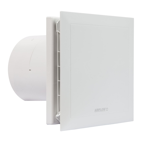
- Page 1 Installation and Operating Instructions QuietAir 150mm Axial Fan MODEL:QT 150HT - Two Speed Fan (220/260m /hr) With Delay Start, Automatic Humidity control and Timer • Low Energy • Quiet • Long Life • Extra Safe • Delay Start...
-
Page 2: Table Of Contents
Installation and Operating Instructions CONTENTS Chapter 1. GENERAL INSTALLATION AND OPERATION INSTRUCTIONS Important Information Warnings Safety Instructions Warranty claims – Disclaimer Regulations - Guidelines Transport Acceptance of delivery Storage Operational area Performance data 1.10 Noise data Chapter 2. GENERAL NOTES Qualification of staff Touch protection Motor protection... -
Page 3: Important Information
CHAPTER 1 Important information To ensure the proper functioning and for your own safety, the manual should be read and observed. GENERAL SAFETY This document is part of the product and should be available at all times to ensure INSTRUCTIONS the safe operation of the fan. -
Page 4: Warranty Claims - Disclaimer
Warranty claims – Disclaimer All versions of this manual should be observed; otherwise the guarantee will be annulled. The same applies to liability claims against Airflow Developments Limited. Any potential damages are not a subject of the guarantee. Changes and modifications to the product are not allowed and will result in a loss of conformity - in such case any warranty and liability will be excluded. -
Page 5: Operational Area
QuietAir 150 fans are used to convey normal or slightly dusty (particles size < 10 µm), little aggressive and humid air, into moderate climate and suitable area of its performance curve (see Airflow sales documentation / Internet). Operation permitted only for fixed installation within buildings. Maximum permitted medium and ambient temperature is 40ºC. -
Page 6: Motor Protection
Motor protection The QT150 HT has an energy-saving maintenance-free EC Motor with high efficiency. The motor is equipped with a thermal contact, wired in series, which automatically switches on/off after cooling. If the motor is blocked there will be an attempt to restart it every 3 seconds. -
Page 7: Chapter 4. Function
Automatic mode: The humidity control works without connecting a switch. Demand ventilation: By connecting e.g. a 2 speed switch from the Airflow range of accessories the fan can be used on different speed levels 1 and 2. The use of the switch is consistent with the functions of the fan by default. - Page 8 Occasional control (faster increase in humidity) With a rapid increase in humidity (caused possibly by showering, bathing) the fan turns on as early as possible before reaching the set threshold, to effectively eliminate excessive humidity and restore the comfort zone in the room. When reaching the set point threshold, the fan shuts down according to the timer setting.
-
Page 9: Cleaning
7. Follow-up After switching off the current stage, the fan turns off after the set run time. The length of the overrun time is adjusted by the DIP switches 3 and 4 (6, 10, 15, 21 minutes). If you switch between stages, the delay time will be ignored. By simultaneous shut down of the both stages, applicable delay time can be ignored. -
Page 10: Chapter 6. Installation
All of the following information and instructions are intended for use by authorized electricians. CHAPTER 6 Scope of delivery / Mechanical Installation A visual inspection upon delivery should be performed including a check to ensure all components are present. Take the unit out of the box immediately before installation INSTALLATION in order to avoid possible damage and contamination during the transport as well as at the construction site. - Page 11 Fig 4 Fig 5 2. Boreholes Position the housing, then mark and drill the holes and mount it with at least two fastening screws and wall plugs. 3. Backdraft shutter and guide vane - If required backdraft shutter (included in delivery) can be installed behind the guide vane (Fig 6).
-
Page 12: Electrical Installation
Electrical installation/Commissioning DANGER Safety instructions listed in Chapter 1.2 should be observed All electrical installations to be carried out by an approved electrician in accordance with presented manual and wiring diagrams. The relevant standards, safety regulations (for instance DIN VDE 0100) and technical connection regulations of the energy supply company should be observed! An all-pole mains switch/isolation switch, with at least a 3 mm contact... -
Page 13: Mounting
Fig 8 Fig 9 - Length of individual wires 135 mm 1. Terminal compartment cover put on the - Wire stripping 8 mm plastic housing and screw tight - Strip the non-metallic sheathed cable which 2. Fit and snap in the cover sits flush with cable duct Mounting Fig 11... -
Page 14: Chapter 7. Installer Function
CHAPTER 7 Function description QT150 HT (Humidity Timer Model) Exceeding the humidity threshold or ventilation on demand by switching the switch leads to activation of the fan. INSTALLER FUNCTION In case of defective humidity sensor both the automatic mode and the demand ventilation won’t work. - Page 15 3. Humidity functions Single-stage, dual-stage and infinitely variable humidity function can be chosen with a combination of dip switches 6, 7 and 8. The choice of the humidity function is technically at certain fan levels bound to the allocation of timer functions (see table below).
- Page 16 Occasional control (faster increase in humidity) With a rapid increase in humidity (causes e.g. by showering, bathing) the fan turns on as early as possible before reaching the set threshold, to eliminate effectively excessive humidity and restore the comfort zone in the room. When reaching the turn off threshold, the fan shuts down according to the timer setting.
- Page 17 9. Push-button operation When no delay start is activated (DIP switch 1 / 2 = off / off), switch inputs 1 or 2 can be controlled by an impulse button. To do so, on the relevant stage, the timer function has to be activated (DIP switch 7, DIP switch 8). The button must be pressed for more than 0.5 sec.
- Page 18 12. Schematic overview for QT150 HT Fig. 14...
-
Page 19: Chapter 8. Care And Maintenance
Mains voltage check Check connection according to wiring diagram - Blocked impeller Clear blockage, clean or replace - Blocked motor Contact Airflow Technical Support Fuse Tripping - Winding is short-circuiting Contact Airflow Technical Support the motor - Damaged cable or... -
Page 20: Decommissioning And Disposal
Decommissioning and disposal Safety instructions listed in Chapter 1.2 should be observed! During transportation safety instructions listed in Chapter 1.4 should be observed. Parts and components of the fan which have reached the end of their CAUTION lifespan, for instance because of the wear and tear, corrosion, mechanical loading, fatigue and/or other effects that could not be directly discerned, should be disposed in accordance with local and international laws and regulations. - Page 21 5. Has been installed in accordance with latest Building Regulations and IEE wiring regulations. Airflow Developments shall not be liable for any loss, injury or other consequential damage, in the event of a failure of the equipment or arising from, or in connection with, the equipment excepting only that nothing in this condition shall be construed as to exclude or restrict liability for negligence.
- Page 22 Addendum – 10/2016 The Building Regulations 2010, Statutory Instrument Part 9, paragraph 42, imposes a requirement that testing and reporting of mechanical ventilation performance is conducted in accordance with an approved procedure. Compliance with this requirement by an assessed and registered ‘Competent Person’ should follow a ‘Best Practice’...
Need help?
Do you have a question about the QT 150HT and is the answer not in the manual?
Questions and answers