Table of Contents
Advertisement
Quick Links
Prior to Using This Document: Videology reserves the right to modify the information in this
document as necessary and without notice. It is the user's responsibility to be certain they possess the
most recent version of this document by going to www.videologyinc.com, searching for the model
number, and comparing revision letters on the respective document, located in the document's footer.
For technical assistance with this product, please contact the supplier from whom the product was
purchased.
Videology Imaging Solutions, Inc. USA
37M Lark Industrial Parkway
Greenville, RI 02828
Tel: 401-949-5332
Fax: 401-949-5276
www.videologyinc.com
Doc # INS-07019 rev A
Revision: A Preliminary
IMAGING SOLUTIONS INC.
Original Equipment Manufacturer
USB Photo ID Cameras
Instruction Manual
Videology Viewers
SFT-07019 and SFT-07019-WHQL
TWAIN Data Source SFT-10011
20/21K13XUSB-C
24B1.3XUSB-C
20/21K14XUSB-C
20/21K15XUSB-C
60V002USB-C
All cameras shown with optional lens
24C1.3XUSB
20/21K758USB
24C7.38USB
Videology Imaging Solutions, B.V. Europe
20/21K758USB-SYS
Neutronenlaan 4
NL-5405 NH Uden, Netherlands
Tel: +31 (0) 413-256261
Fax: +31 (0) 413-251712
www.videology.nl
Issue Date: 07/22/2011
Page 1 of 42
Advertisement
Table of Contents

Subscribe to Our Youtube Channel
Related Manuals for Videology SFT-07019

Summary of Contents for Videology SFT-07019
- Page 1 24C7.38USB All cameras shown with optional lens Prior to Using This Document: Videology reserves the right to modify the information in this document as necessary and without notice. It is the user’s responsibility to be certain they possess the most recent version of this document by going to www.videologyinc.com, searching for the model number, and comparing revision letters on the respective document, located in the document’s footer.
- Page 2 The Software is licensed, not sold, to you for use only under the terms of this Agreement. Videology grants to you, the purchaser, the right to use all or a portion of this Software provided that the Software is used only in conjunction with Videology's family of products.
-
Page 3: Table Of Contents
Table of Contents Document History ......................... 5 Overview ..........................5 2.1. The Videology USB Camera Family ........................5 2.2. Contents ................................5 Features ..........................6 3.1. 24C7.38USB ............................... 6 ... - Page 4 8.3.9. Help (About Menu) ............................39 ALL MODELS - Using the TWAIN Interface ................40 Troubleshooting ....................... 40 10.1. Focus Issues..............................40 10.2. Noisy or Grainy Video ............................40 10.3. ...
-
Page 5: Document History
2. Overview 2.1. The Videology USB Camera Family Videology USB Cameras provide a quick and easy means of displaying and capturing high quality video ® and images on any USB 2.0 equipped desktop or laptop computer running a supported Microsoft Designed with flexibility in mind, each camera model has its own distinct advantage, whether speed, resolution, image quality, sensitivity or price. -
Page 6: Features
Software Development Kit available Software WDM device drivers digitally signed by Microsoft under Windows XP, Vista and Windows 7 (SFT-07019-WHQL) DirectX/DirectShow compliant TWAIN compliant FIPS 201 compliance (in conjunction with appropriate software) Linux driver (in development) ... -
Page 7: 20/21K1Xxusb-C
Microsoft digital certification for WDM device drivers are available under Windows XP, Vista and 7 (SFT-07019-WHQL) DirectShow compliant TWAIN compliant (requires Videology’s TWAIN data source for Windows Vista and 7 operating systems) 1.1. 24B1.3XUSB-C CMOS, USB 2.0, 1.3 Megapixel Sensor, B&W Single Board Camera Progressive Scan, 1.3 Megapixel CMOS Sensor (Square Pixels) -
Page 8: Mounting Method
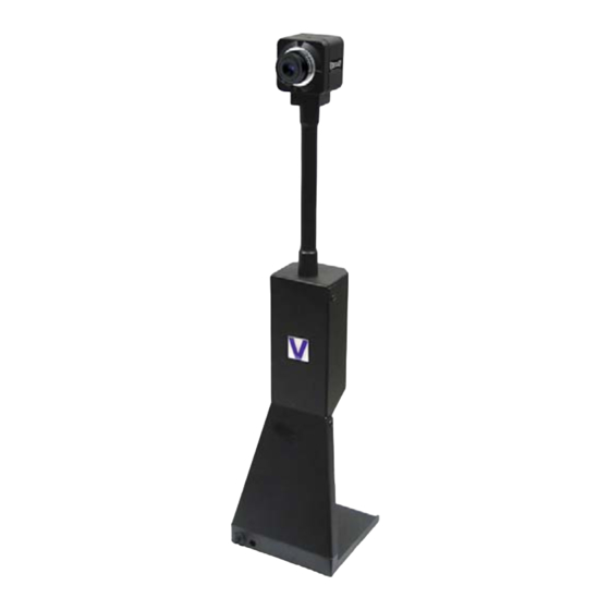
4. Mounting Method The cameras (20K758USB and 24C7.38USB) are fitted with a ¼-twenty screw thread so that any common tripod can be used. ¼-twenty mount The 20K758USB-SYS has a unique stand 20K758USB-SYS that integrates the camera with a stand that exploded assembly can withstand a 40 degree tilt and still stabilize upright. -
Page 9: Minimum System Requirements
5. Minimum System Requirements A PC with USB 2.0 compatible port. MAC is not supported. USB 1.1 is not supported. Preview only PIII- 1.1GHz or above 128MB of RAM (256MB preferred) Windows XP/2000 for USB2.0 9.0c or later DirectX/DirectShow ... -
Page 10: Viewer And Usb Driver Installation
Do not connect the camera to the computer before installing the software. 6.1. Viewer Installation (All Models) Insert the CD labeled USB Viewer Software (SFT-07019 or SFT-07019-WHQL). Click the executable file named SetupVid.exe. Videology's viewer software automatically checks which operating system is running and loads the appropriate drivers (32bit or 64bit). - Page 11 Click Next to continue. ® Next, the Windows Security window opens informing that the WDM device drivers are Microsoft digitally certified. Depending on the software version one of these windows will open: Doc # INS-07019 rev A Issue Date: 07/22/2011 Revision: A Preliminary Page 11 of 42...
- Page 12 SFT-07019-WHQL SFT-07019 Click Install or Continue Anyway. Doc # INS-07019 rev A Issue Date: 07/22/2011 Revision: A Preliminary Page 12 of 42...
- Page 13 The driver and viewer installation is now complete. Click Finish. Click Close to exit the hardware wizard. Doc # INS-07019 rev A Issue Date: 07/22/2011 Revision: A Preliminary Page 13 of 42...
-
Page 14: Twain Installation
7. TWAIN Installation To install the TWAIN data source, insert the CD labeled Twain Data Source and double click the executable file named SFT-10011 - TDS -Rev 2-1-11.exe. Note: the file name might be slightly different depending on the revision level of the software. The following window will appear: If the viewer is to be installed in a location other than the default directories, click on the Browse button and specify the desired location, otherwise click on the Install Button and the following screens will... -
Page 15: Using The Videology Viewer
8. Using the Videology Viewer After software installation, plug in the USB cable. A window will pop up stating that Windows is installing the device drivers: Upon completion a second window will state the driver software installed successfully: NOTE: There is no auto focus feature in these cameras. Once camera is focused, the user can modify the settings. -
Page 16: Models 2Xk1Xxusb-C
8.1. MODELS 2XK1XXUSB-C To launch the viewer software, simply click on the Videology Icon on the Desktop. A window will appear displaying the camera image. 8.1.1. Using the Control Panel Clicking on the Control option on the menu bar will display the control panel. The control panel can be used to make changes to the camera settings. -
Page 17: Shutter Mode
The shutter speed of Videology USB cameras can be varied from 1/50 second to 1/10000 second. There is an automatic setting (Electric Iris), in which the shutter speed is adjusted automatically according to the overall light level. - Page 18 NOTE: Videology supplies the camera's default option in BLC with a center weighting. BLC will only function when the shutter speed is set to “Electric Iris.” The effect of Back Light Compensation is shown in the following images. Back Light Compensation OFF (top image) and Back Light Compensation ON (Bottom Image).
-
Page 19: Mirror Mode
8.1.4. Mirror Mode The mirror mode option is simply used to provide a mirror inversion of the image. This feature is used when the camera is viewing the subject through a mirror. 8.1.5. Reset The Reset feature is used to restore all the settings to the factory default values. Doc # INS-07019 rev A Issue Date: 07/22/2011 Revision: A Preliminary... -
Page 20: Edge Enhancement
8.1.6. Edge Enhancement Edge enhancement is used to make the edges of lines appear sharper and more distinct. It gives the appearance of increased resolution, but in reality the resolution is determined purely by the number of pixels, and is fixed. The effect of edge enhancement is illustrated below. -
Page 21: Manual Gain
8.1.7. Manual Gain Manual Gain provides a means of controlling the overall image brightness. Gain can be set to automatic (unchecked), in which case the camera will automatically adjust to variation in illumination and subject matter or manual (checked) in which the user controls the variation in illumination and subject matter. -
Page 22: White Balance (Wb) Mode
8.1.8. White Balance (WB) Mode Under varying lighting conditions, (sunlight, fluorescent lighting etc) the perceived color of objects will change. This is true for the human eye and also for the video camera. The color spectrum of a light source varies according to its’ temperature. -
Page 23: Advanced Options
8.1.9. Advanced Options Advanced Settings can be selected by Options > Advanced Options… When Advanced Options is selected, the Advanced Options window is opened. Figure 1. Advanced Properties Menu 8.1.9.1. Isochronous and Bulk transfer modes. There are two basic transmission modes for data on the USB bus. These are referred to as Isochronous and Bulk Transfer. -
Page 24: Still Image Capture (Snap Feature)
If multiple USB cameras are operated simultaneously, it is possible that the data rate from the camera will be reduced; resulting in a slower frame rate for the displayed image, and under this situation the isochronous display should be used. If only one camera is being used, then the bulk transfer mode will probably provide the fastest display. -
Page 25: Model 24B1.3Xusb-C
8.2. MODEL 24B1.3XUSB-C To launch the viewer software, simply click on the Videology Icon on the Desktop. A window will appear displaying the camera image. 8.2.1. Camera Settings The Camera Settings (gain, shutter speed etc.) can be selected via Options > Camera Settings…... -
Page 26: Gain Control
Gain Control Shutter Speed Mirror Mode and Flip Mode Version of Gain Control Software Figure 2. Video Capture Filter Properties 8.2.1.2. Gain Control The gain control is used to vary the image contrast. To alter the gain, simply move the slider control and click on the Apply button on the bottom right corner of the box. -
Page 27: Capture Format
8.2.2. Capture Format Capture Format can be selected by Options > Capture Format… 8.2.2.1. Video Capture Pin Properties When Capture Format is selected, the Video Capture Pin Properties window is opened. Figure 3. Video Capture Pin Properties Frame Rate The Frame rate will vary depending upon the screen resolution. Color Space/Compression The Color Space/Compression is fixed to UYVY and cannot be varied. - Page 28 Output Size Resolution (pixels) Maximum Frame rate 320 x 240 (default) 15 fps 320 x 240 15 fps 640x 480 15 fps 1280 x 1024 15 fps 1024 x 768 15 fps 800 x 600 15 fps Table 1 Maximum Frame Rate for various screen resolutions. 320 x 240 640 x 400 800 x 600...
-
Page 29: Advanced Options
8.2.3. Advanced Options Advanced Settings can be selected by Options > Advanced Options… When Advanced Options is selected, the Advanced Options window is opened. Figure 4. Advanced Properties Menu 8.2.3.1. Isochronous and Bulk transfer modes. There are two basic transmission modes for data on the USB bus. These are referred to as Isochronous and Bulk Transfer. -
Page 30: Still Image Capture (Snap Feature)
8.2.3.2. Still Image Capture (Snap Feature) The Image Snap feature is used to acquire and store still images from the video display and is initiated by selecting the Take Snapshot Option under the File menu. The “Set Snap Image Folder…” button is used to change the location where snapshot images will be saved. -
Page 31: Model 24C1.3Xusb
8.3. MODEL 24C1.3XUSB To launch the viewer software, simply click on the Videology Icon on the Desktop. A window will appear displaying the camera image. 8.3.1. Camera Settings The Camera Settings (gain, shutter speed etc.) can be selected via Options > Camera Settings…... -
Page 32: Parameters
Backlight Parameters Compensation White Balance Version of Edge Software Enhancement 8.3.1.3. Parameters 8.3.1.3.1. Shutter Speed The camera’s shutter speed is analogous to the shutter speed of a conventional camera, although for a solid state imager there is no physical shutter. For this type of camera “shutter speed” refers to an electronic shutter, which determines the length of time over which charge is accumulated on the image sensor. -
Page 33: Mirror And Flip Mode
8.3.1.6. Mirror and Flip Mode The Mirror and Flip options are used to create images, which are mirrored about the Vertical and Horizontal axis respectively. 8.3.1.7. Mains Freq This is set to 50 Hz or 60 Hz to keep the shutter in sync with the line frequency. 8.3.1.8. -
Page 34: Capture Format
8.3.2. Capture Format Capture Format can be selected by Options > Capture Format… 8.3.2.1. Video Capture Pin Properties When Camera Format is selected, the Video Capture Pin Properties window is opened. Figure 5. Video Capture Pin Properties Frame Rate The Frame rate will vary depending upon the screen resolution. Color Space/Compression The Color Space/Compression is fixed to UYVY and cannot be varied. - Page 35 Output Size Resolution (pixels) Maximum Frame rate 320 x 240 (default) 15 fps 320 x 240 15 fps 640x 480 15 fps 1280 x 1024 15 fps 1024 x 768 15 fps 800 x 600 15 fps Table 2 Maximum Frame Rate for various screen resolutions. 320 x 240 640 x 400 800 x 600...
-
Page 36: 24C13 Zoom/Pan Properties
8.3.3. 24C13 Zoom/Pan Properties Zoom/Pan Box The red square is the area of interest. The zoom feature enables the user to change where the viewing area is located. This area is dependent on what output size is selected within the Video Capture Pin Properties (section 8.3.2.1). Doc # INS-07019 rev A Issue Date: 07/22/2011 Revision: A Preliminary... -
Page 37: Advanced Options
8.3.4. Advanced Options Advanced Settings can be selected by Options > Advanced Options… The Advanced Options window is opened. Figure 6. Advanced Opptions Menu 8.3.4.1. Isochronous and Bulk transfer modes. There are two basic transmission modes for data on the USB bus, referred to as Isochronous and Bulk Transfer. -
Page 38: Restart Graph
NOTE: When changing the transfer mode from Isochronous to Bulk, it is necessary to close the application, unplug and reconnect the camera, and restart the application. 8.3.5. Restart Graph 8.3.6. Factory Reset Factory Reset will bring up a dialog box. If “OK” is selected the camera will be reset the next time it is plugged into the PC. -
Page 39: Still Image Capture (Snap Feature)
8.3.7. Still Image Capture (Snap Feature) The Image Snap feature is used to acquire and store still images from the video display and is initiated by selecting the Take Snapshot Option under the File menu. The “Set Snap Image Folder…” button is used to change the location where snapshot images will be saved. -
Page 40: All Models - Using The Twain Interface
If the Twain interface (SFT-10011) is installed the camera can be used with any TWAIN Compliant Application. The TWAIN interface will attach itself to the first Videology camera it finds connected to the computer. For best operation, run the TWAIN Interface on a system that has only one Videology camera installed. -
Page 41: Reflections
Windows XP Make sure that the camera is plugged into one of the USB ports. Insert the Videology CD that was provided with the camera into a CD-ROM drive. The “Videology USB2.0 Camera Installation Wizard” software will run automatically. If the autorun.exe software does not run automatically, browse the CD files and double click on the “autorun.exe”... -
Page 42: Revision: A Preliminary
Please visit our website at: http://www.videologyinc.com VIDEOLOGY IMAGING SOLUTIONS is an ISO 9001 registered video camera developer and manufacturer serving industrial, machine vision, biometric, security, and specialty OEM markets. Videology designs, develops, manufactures, and distributes video, image acquisition, and display technologies and products to OEMs worldwide.
Need help?
Do you have a question about the SFT-07019 and is the answer not in the manual?
Questions and answers