Sanyo Denki Sanmotion R Instruction Manual
Ac servo system
Hide thumbs
Also See for Sanmotion R:
- Instruction manual (398 pages) ,
- Quick start manual (58 pages) ,
- Manual (42 pages)
Table of Contents
Advertisement
Advertisement
Chapters
Table of Contents
Troubleshooting

Related Manuals for Sanyo Denki Sanmotion R


Summary of Contents for Sanyo Denki Sanmotion R
- Page 1 M0009143C TYPE (DC48V) Pulse Input Type For Rotary Motor...
- Page 3 Details of revision history The third edition (C) ■ Chapter 2 and 4 A precaution to use battery for main circuit added. ● ■ Chapter 2 A precaution on control power supply added. ● Terminal layout on connector for battery added. ●...
-
Page 4: Installation·································································································································································
Safety precautions Please fully follow Carefully review this operating manual and the supporting documentations to use the product properly before perfoming installation, operation, and maintenance. Use this product after you fully understand sufficient knowledges on all the equipments and safety information, and precautions. - Page 5 Safety precautions Please fully follow Operating precautions ■ WARNING Fully observe the following warnings because of risk of electrical shock and injury. Do not operate the product in explosive atmospheres, because of risk of injuries and fire. Do not perform wiring and maintenance with applying current. These must be done over 10 minutes after breaking main power supply and after confirmation main power supply capacitor discharged, because of risk of electrical shock and damages.
- Page 6 Safety precautions Please fully follow Storage ■ PROHIBITION Do not storage the product in water, hazardous gas, and liquid existed area, failure to observe this causes failure. MANDATORY Storage the product within the specified temperature and himidity range ”-20°C thorugh +65°C, 90%RH”...
-
Page 7: Installation·······························································································································································
Safety precautions Please fully follow Installation ■ CAUTION Do not put heavy things or get on top of the product, because of risk of injuries. Fully observe installation direction, failure to observe this causes fire and failure. Do not let fall and apply high impacts on the products. Failure to observe this causes failure. - Page 8 Safety precautions Please fully follow Operation ■ CAUTION Never make excessive adjustment change as the operation becomes unstable, and there is risk of injuries. Fix servo motor apart from mechanical equipments to perform test operation and install in the machine after operation check, because of risk of injuries. Holding brake is not a stopping device to secure machine safety.
- Page 9 Safety precautions Please fully follow MANDATORY Externally place emergency stop circuit so as to immediately stop operation and disconnect power supply. Incorporate safeguard circuit into the outside of servo amplifier so as to disconnect main circuit power when alarm activated, because of risk of going out of control, injuries, burnout, fire, and secondary damages.
- Page 10 Table of contents Table of contents Preface 1.1 Introduction ······························································································································································· 1-1 1) Changes and additions to AC Servo amplifier SANMOTION R (previous model) ··················································· 1-1 1.2 Instruction Manual ···················································································································································· 1-2 1) Contents·································································································································································· 1-2 2) Precautions on this manual····································································································································· 1-2 1.3 Illustration of System Components ··························································································································· 1-3 1.4 Model number structure ············································································································································...
- Page 11 Wiring 4.1 Wiring of main circuit power supply, control power supply, servomotor, and protective grounding. ·························· 4-1 1) Name and function ·················································································································································· 4-1 2) Electrical wire·························································································································································· 4-1 3) Wire diameter - allowable current ··························································································································· 4-1 4) Terminal layout of connector CNA and CNB ··········································································································· 4-2 5) Recommended wire diameter and cable length ······································································································...
- Page 12 7) Monitoring servo gain adjustment parameters ······································································································ 6-10 8) Manual tuning method using auto-tuning results··································································································· 6-10 6.3 Automatic tuning of notch filter································································································································ 6-11 Operation method··········································································································································· 6-11 Parameters to be set ······································································································································ 6-11 6.4 Automatic tuning of FF vibration suppression frequency ························································································ 6-12 Operation method···········································································································································...
- Page 13 9.3 Specification for regenerative unit··························································································································· 9-10 1) Specification·························································································································································· 9-10 2) Internal block diagram··········································································································································· 9-10 3) Regenerative unit front view·································································································································· 9-11 4) Connection diagram of regenerative unit ·············································································································· 9-12 5) Calculation of regenerative effective electrical power ··························································································· 9-14 Appendix 10.1 Conformance to standards···································································································································· 10-1 1) Conformance to standards ····································································································································...
- Page 14 No Text on This Page.
-
Page 15: Table Of Contents
Preface 1.1 Introduction ................................1-1 1) Changes and additions to AC Servo amplifier SANMOTION R (previous model) ............1-1 1.2 Instruction Manual ..............................1-2 1) Contents ..................................1-2 2) Precautions on this manual ............................1-2 1.3 Illustration of System Components .......................... 1-3 1.4 Model number structure ............................ -
Page 16: Introduction
Introduction 1.1 Introduction AC servo amplifier “SANMOTION R ADVANCED MODEL low voltage-input type” is a small and one axis servo amplifier with 2 kinds of capacities, to which main circuit power DC48V<24V> and control power DC5V are input as external power supply. This model corresponds to rotary motor “series R,”... -
Page 17: Instruction Manual
This manual describes specification, installation, wiring, operation, functions, maintenance of AC servo amplifier “SANMOTION R ADVANCED MODEL, low voltage-input type” as in the following order: The figures in parentheses for main circuit voltage described in this manual are the values when the voltage is DC24V. -
Page 18: Illustration Of System Components
1. Preface System configuration 1.3 Illustration of System Components The folowing shows an example of system configulation. SANMOTION R ADVANCED MODEL (Low voltage-input type) Direct current DC5V Power input Direct current DC48V <24V> Install this for the possibility of regenerative energies... -
Page 19: Model Number Structure
1. Preface Model number of servo motor 1.4 Model number structure 1) Model number of servo motor Series R Specification identification 00・・・Standard 01・・・With oil seal Servo motor type Encoder type 2・・・Medium H・・・Absolute encoder for incremental system P・・・Battery backup method absolute encoder Power-supply W・・・Battery less absolute encoder voltage... -
Page 20: Model Numbers Of Servo Amplifier (Abbreviated Model Numbers)
1. Preface Model number of servo amplifier 2) Model numbers of servo amplifier (abbreviated model numbers) Separate Series RF2 specification 00・・・Standard 01・・・no DB Input voltage current G・・・DC48V H・・・DC24V Servo amplifier size 11・・・Small-sized 21・・・Large-sized Interface type Servo motor type A・・・Pulse input, NPN (sink) output A・・・Rotary motor Motor encoder type 0・・・Serial encoder... -
Page 21: Part Names
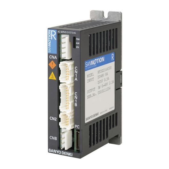
1. Preface Part names of servo amplifier 1.5 Part names 1) Servo amplifier Front view POW: LED for indication control Connector for inputting power supply power established ALM:LED for alarm CNA: Plug-side model number STA:LED for status Housing:VHR-5N Contact:SVH-21T-P1.1 or Connector A for I/O signal for host equipment SVH-41T-P1.1 CN1A: Plug-side model number... -
Page 22: Servo Motor
1. Preface Part names of servo motor 2) Servo motor ■ Lead type R2□A04○○○△□◇ R2□A06○○○△□◇ Encoder Frame Shaft Flange Encoder cable Servo motor power cable Brake cable... - Page 23 2. Specification Servo motor ................................2-1 Common specification............................2-1 Servo motor external dimension, specification, and weight.................. 2-1 Mechanical specification, strength, and engineering precision ................2-1 Oil seal type ................................. 2-2 Holding brake............................... 2-3 Degree of decrease rating for R2AA Motor, depending on with or without oil seal/brake ........2-3 Motor encoder................................
-
Page 24: Specification
2. Specification Servo motor 2.1 Servo motor Common specification Series Servo motor series R2 Time rating Continuous Insulation Class F classification Dielectric strength AC1500V for 1minute voltage Dielectric resistance DC500V, over 10MΩ Fully closed, self-cooled Protection method Motor flange angle shall be 80 or less: IP67 (Except for motor passed-through part and cable tip.) Motor flange angle shall be 80 or less: none (Except for Oil sealing... -
Page 25: Oil Seal Type
2. Specification Servo motor Shock resistance ■ Servo motor shaft shall be installed in the horizontal direction as indicated in the figure below so that the shaft is tolerant of 98m/s of impact acceleration when being applied a vertical impact twice. -
Page 26: Holding Brake
2. Specification Servo motor Holding brake An optional holding brake is supplied with the servo motor. This brake shall not be used as braking except in emergency as this is designed to hold. Use “the timing signal output for holding brake” to turn on/off the brake excitation. -
Page 27: Motor Encoder
2. Specification Motor encoder 2.2 Motor encoder Serial encoder ■ Absolute Encoder for Incremental System Model Resolution Synchronization Transmission Transmission scheme scheme rate PA035S Divided into 131072 Start/stop Half duplex serial 2.5Mbps (17bit) synchronization communication Battery Backup Method Absolute Encoder ■... -
Page 28: Battery Specification
2. Specification Motor encoder and battery ■ Servo motor rotation direction and encoder signal pulses of pulse encoder Motor rotation direction and motor encoder signal phases are related as follows: Servo motor rotation direction-Normal Phase A pulse 90° Phase B pulse Phase Z Phase B is ahead of Phase A 90°... -
Page 29: Servo Amplifier
2. Specification Servo amplifier 2.3 Servo amplifier Common specification General specification ■ Control function Position control Control system MOS-FET:PWM control, sine wave drive Main circuit power DC48V<24V>±10% supply Control power supply DC5V±5% Operating ambient temperature 0 through 40 degree Celsius Operating storage temperature -20 through +65 degree Celsius Operating and storage humidity... -
Page 30: Input Command, Position Output Signal, General-Purpose Input Signal, And General-Purpose Output Signal
2. Specification Input command Input command, position output signal, general-purpose input signal, and general-purpose output signal Input command ■ 5M PPS Maximum input (reverse rotation + normal rotation pulse and code + pulse) pulse frequency 1.25M PPS (90°-phase-difference, two-phase pulse) Normal rotation + reverse rotation command pulse,code + Position Input pulse... - Page 31 2. Specification General-purpose input and output Position output signal ■ Encoder output N/32768 (N=1 through 32767),1/N(N=1 through 64) or 2/N(N=2 through 64) Pulse frequency dividing General-purpose input signal ■ Interactive photo coupler (sink, source connection):×8-input Externally supplied power:DC5V±5%/DC12V through DC24V±10%,more than 100mA (DC24V) Servo-on, alarm reset, torque limit, encoder-clear, forward rotation prohibit, Sequence input signal...
-
Page 32: Power Supply And Amount Of Heat Generation
2. Specification Power supply and amount of heat generation 2.4 Power supply and amount of heat generation Input current of main circuit power supply and control power supply Input current of Input current of Rated output main circuit power control power Servo amplifier Servo motor model supply... -
Page 33: Cautions On Load
2. Specification Cautions on load 2.5 Cautions on load Restrictions on acceleration time, deceleration time,and effective torque Motor acceleration time and deceleration time shall be subject to the restriction of momentary range of torque-rev characteristic of motor being operated together. Repetitions of motor operation and stop, and load torque are subject to the restriction of rated torque. -
Page 34: Position Signal Output
2. Specification Position signal output 2.6 Position signal output The amplifier outputs two (2) kinds of position signals: Serial signals and Pulse signals Positions signals by serial signals ■ The following serial encoders output absolute position data (encoder signal output -PS-) from the absolute encoder of the servo amplifier using serial signals. -
Page 35: Binary Code Output Format And Transfer Period
2. Specification Position signal output Binary code output format and transfer period Format ■ Data format ◆ 11bits 11bit 1bit 5bit 3bit 1bit 1bit Start bit Data bit Address bit Stop bit Parity bit Transfer format ◆ Start bit Data bit Address bit Parity bit Stop bit ・Data 1... -
Page 36: Ascii Decimal Code Output Format And Transfer Period
2. Specification Position signal output ASCII decimal code output format and transfer period Format ■ Data format ◆ 10bit 1bit 7bit 1bit 1bit Parity bit Start bit Data bit Stop bit Transfer format ◆ Data number Start bit Parity bit Stop bit Data 1 Show position data ”P”... -
Page 37: Position Signal Output From Pulse Signal
2. Specification Position signal output Position signal output from pulse signal Servo amplifier outputs “90°-phase difference two-phase pulse (phase A, phase B) and original phase ■ (phase Z)”. Pulse output can change the division ratio by parameter. Set the general parameter “Group C ID04 Encoder Output Pulse Division [ENRAT]” ―... -
Page 38: Specifications For Analog Monitor
2. Specification Analog monitor 2.7 Specifications for analog monitor Analog monitor box (an option) ■ Analog monitor can monitor by connecting analog monitor box to connector for analog monitor on the bottom of servo amplifier. Analog monitor box needs power supply of ±12V separately. Please be advised that this is user prepared item. -
Page 39: Specifications For Dynamic Brake
2. Specification Dynamic brake 2.8 Specifications for dynamic brake Allowable frequency, instantaneous tolerance, decreasing the rotation angle of the dynamic brake Allowable frequency of the dynamic brake (main circuit power ON/OFF) ■ Less than 10 times per hour and 50 times per day at maximum velocity within the applied load inertia moment. - Page 40 No Text on This Page.
- Page 41 Installation 3.1 Installation .................................. 3-1 1) Servo amplifier................................3-1 2) Unpacking................................... 3-2 3) Installation direction and position..........................3-3 4) Conditions on layout in control cabinet ........................3-3 5) Cooling conditions ..............................3-4 3.2 Servo motor ................................3-5 1) Precautions................................. 3-5 2) Unpacking...................................
-
Page 42: Installation
3. Installation Servo amplifier 3.1 Installation 1) Servo amplifier Fully observe the following precautions to perform installation. ■ Precautions Installation in flammable material or its vicinity causes fire. Do not put heavy things and get on top of servo amplifier. Operate within the scope of specified ambient conditions. -
Page 43: Servo Amplifier
3. Installation Servo amplifier 2) Unpacking The following items shall be checked when the product delivered. In the event that any abnormal items are found, please contact us. ■ Check servo amplifier model number to see if any discrepancies between ordered item and delivered item. -
Page 44: Installation Direction And Position
3. Installation Servo amplifier 3) Installation direction and position 4) Conditions on layout in control cabinet ■ Make space of over 50mm above and under servo amplifier not to prevent airflow from the interior of heat sink and servo amplifier. Create flow with cooling fan if heat remains in the vicinity of servo amplifier. -
Page 45: Cooling Conditions
✔ Perform measuring with the operating pattern requiring the strictest load condition. ✔ Recommended FAN motors are as follows: Manufactured by Sanyo Denki Co., Ltd.: DC San series Ace, square type: 60mm, 80mm (General model) Manufactured by Sanyo Denki Co., Ltd.: San Ace series L, square type: 60mm, 80mm (Long-life model) Please contact our sales department if you use FAN motor. -
Page 46: Servo Motor
3000min 3φ-・ CI.F IP40 SER No.090206001 2002 SANYO DENKI MADE IN JAPAN 00482921-01 Serial number 3) Installation The following items shall be checked on installation location and method. Servo motor is designed to be used indoors. Install servo motor indoors. -
Page 47: Water And Dust Proofing
3. Installation Servo motor 4) Installation ■ Installation in horizontal direction, on the axis ends, and downward is available. ■ Horizontal or downward placement is recommended, for reducer with lubricant agent like oil or grease applied onto its output shaft, or output shaft exposing to liquid. Even in the case of models with oil seal (optional extras) attached on the output shaft side, oil may invade internal motor and this causes malfunction, due to worn oil seal and respiratory operation under the circumstance oil seal lip constantly exposures to oil when shaft installed upward. -
Page 48: Protective Cover Placement
3. Installation Servo motor 6) Protective cover placement ■ Place protective cover as indicated in the figure below in the environment that motor constantly exposure to liquid. ■ Direct connector (lead outlet) downward at the range of angle indicated in the figure below. ■... - Page 49 3. Installation Servo motor ■ Perform final centering for motor shaft and mating machine as indicated in the figure below correctly. Be aware of risk of damages to output shaft due to minor misalignment of shaft, when using rigid boy coupling. The difference between maximum and minimum value shall be 3/100mm or less, by measuring 4 points on the whole...
-
Page 50: Allowable Load For Bearing
3. Installation Servo motor ■ Use exclusive removal jig to remove gear or pulley. Tapered Removal jig Allowable load for bearing ■ Allowable load for servo motor is as indicated in the table below. Do not apply excessive thrust or radial load to servo motor. When performing belt drive, make sure axis conversion value of belt tension shall not exceed the allowable values in the table below. -
Page 51: Cable Installation And Its Related Cautions
3. Installation Servo motor 9) Cable installation and its related cautions ■ Be careful not to apply excessive stress and damages onto cables. ■ When installing cables in the place servo motor can move, take sufficient inflective radius so as not to apply excessive stress onto cables. - Page 52 No Text on This Page.
- Page 53 Wiring 4.1 Wiring of main circuit power supply, control power supply, servomotor, and protective grounding....4-1 1) Name and function ..............................4-1 2) Electrical wire ................................4-1 3) Wire diameter - allowable current ..........................4-1 4) Terminal layout of connector CNA and CNB ....................... 4-2 5) Recommended wire diameter and cable length......................
-
Page 54: Wiring
4. Wiring Electrical wires 4.1 Wiring of main circuit power supply, control power supply, servomotor, and protective grounding. 1) Name and function Name Connector and pin number Remarks Main circuit power Pin 4 and 5 of CNA Inputs main circuit power apply (DC48V<24V>±10%) Control power Pin 2 and 3 of CNA Inputs control power supply (DC5V±5%) -
Page 55: Terminal Layout Of Connector Cna And Cnb
4. Wiring Terminal layout of connector CAN and CNB 4) Terminal layout of connector CNA and CNB Terminal layout of CNA ■ Terminal NO. Signal Description FG ( ) Frame ground (earth) Control power DC5V Control power common Main power DC48V<24V> Main power common Model number Applicable wire size... -
Page 56: Recommended Wire Diameter And Cable Length
4. Wiring Recommended wire diameter and cable length 5) Recommended wire diameter and cable length Recommended wire diameters for use in servo amplifier and motor are shown in the table ■ below. Motor input Main circuit power Control power Servo motor Servo amplifier (U・V・W・... -
Page 57: Example Of Wiring
4. Wiring Example of wiring 6) Example of wiring The following shows an example of external wiring. Example of layout ■ Power Servo motor Power input Power Power input Operation Operation Emergency stop Alarm CN1B 12 - 18, 20 (OUT1 - OUT8) DC5V, DC12V-24V ✔... -
Page 58: Wiring Connection Diagram To Host Equipment
4. Wiring Wiring connection to host equipment 4.2 Wiring connection diagram to host equipment 1) Name and pin number of signal CN1A and CN1B (wiring connection to host equipment) Terminal layout of connector interfacing with host equipment ■ CN1-A CN1-A F-PC ―... -
Page 59: Layout Of Connector Cn1-A
4. Wiring Wiring connection to host equipment 2) Layout of connector CN1-A CN1-A PADP-14V-1-S (cable-crimped side) ■ CN1-A Model NO. Applicable wire size Manufacturer Housing PADP-14V-1-S JST Mfg. Co., Ltd. Contact SPH-002GW-P0.5S AWG24 - AWG28 3) Name and its function of signal CN1-A Terminal NO. -
Page 60: Connection Circuit Of Terminal Cn1-A
4. Wiring Wiring connection to host equipment 4) Connection circuit of terminal CN1-A Terminal Mark Name Description Frame ground Connects shielded wire of cables between host controller of CN1-A and servo amplifier. Phase A pulse output Outputs (RS422-compliant) signal of phase A pulse, B pulse, and original phase Z pulse of motor encoder. - Page 61 4. Wiring Wiring connection to host equipment Terminal Mark Name Description F-PC Command pulse output Command pulse input is position command input ― ― ― ― (RS422-compliant). Command pulse output Command input pulse method shall be selected from 3 types. R-PC Command pulse output ―...
-
Page 62: Layout Of Connector Cn1-B
4. Wiring Wiring connection to host equipment 5) Layout of connector CN1-B CN1-B PADP-20V-1-S (cable-crimped side) ■ CN1-B Model NO. Applicable wire size Manufacturer Housing PADP-20V-1-S JST Mfg. Co., Ltd. Contact SPH-002GW-P0.5S AWG24 - AWG28 6) Signal name and its function Terminal Signal Description... -
Page 63: Terminal Connection Circuit
4. Wiring Wiring connection to host equipment 7) Terminal connection circuit Terminal Mark Name Description Frame ground Connects shielded wire of cables between host controller of CN1-A and servo amplifier. CONT-COM General-purpose input General-purpose input circuit shall connect to relay or power supply Open collector transistor circuit. - Page 64 4. Wiring Wiring connection to host equipment Terminal Mark Name Description OUT-PWR For general-purpose General-purpose circuit is connected to photo coupler and relay output power circuit. [NPN-output (sink output)] OUT1 General-purpose OUT-PWR (external power supply) specification output ± OUT2 General-purpose Power-supply voltage range:DC5V 5%,DC12Vthrough24V output...
-
Page 65: Wiring Of Motor Encoder
4. Wiring Wiring of motor encoder 4.3 Wiring of motor encoder 1) Name and function of connector CN2 Battery backup absolute encoder ■ Servo amplifier Servo motor Signal Description Note) lead color for Terminal NO. Power supply Twisted pair Black Power supply common Brown Twisted pair... -
Page 66: Terminal Number On Servo Amplifier Side
4. Wiring Wiring of motor encoder Battery-less absolute encoder ■ Servo amplifier Servo motor Signal Description Note1) lead color for Terminal NO. Power supply Twisted pair Black Power supply common Brown Serial data signal Twisted pair Blue N.C. Unconnected N.C. N.C. -
Page 67: Recommended Specification Of Encoder Cable
4. Wiring Wiring of motor encoder 3) Recommended specification of encoder cable Shielded many-to cable (AWG24 or equivalent) Cable rating 80°C 30V 4) Encoder cable length Maximum cable length according to conductor size of power (5V, SG) wire Battery-back up absolute encoder Conductor Absolute encoder for incremental Battery-less absolute encoder... - Page 68 No Text on This Page.
- Page 69 Operation 5.1 How to change servo motor to be combined......................5-1 1) Change and verify servo motor with use of setup software ..................5-1 5.2 System parameters ..............................5-2 1) Specification confirmation............................5-2 2) System parameters list .............................. 5-4 3) Confirmation and settings of system parameters....................... 5-4 4) Change and verify system parameters (settings for motor encoder specification).............
-
Page 70: How To Change Servo Motor To Be Combined
5.Operation How to change servo motor to be combined 5.1 How to change servo motor to be combined Change and verify servo motor to be combined with servo amplifier you use by using AC servo system supportive tool, “setup software.” Refer to separate operating manual M0008363 for more details on setup software operation. -
Page 71: System Parameters
5.Operation System parameters / Specification confirmation 5.2 System parameters 1) Specification confirmation Confirm specification, combination of servo amplifier and motor encoder by using AC servo system supportive tool “setup software.” Procedure Item and Contents Confirmation of servo amplifier specifications ■ Confirm that the specifications of the product purchased are the same as that of the machine being used. - Page 72 5.Operation System parameters / Specification confirmation Procedure Item and Contents Main circuit power supply voltage Code Main circuit power supply voltage display 03 (04) 48V <24V> Confirm that the main circuit power supply voltage of the connector CNA is displayed. ■...
-
Page 73: System Parameters List
5.Operation System Parameters List, Confirmation and Settings (Servo Amplifier) 2) System parameters list The following is system parameters list. Settings vary depending on system you use. So please confirm 3) and 4) and later to surely and properly set. Contents Control Cycle Main Circuit Power Input Type Reserve... - Page 74 5.Operation Confirmation and Settings (Servo Amplifier) Contents Control Mode Selection ■ Set the control mode of the servo amplifier used as follows: Selection Description Position Position Control Mode Position Control Selection ■ Select the function Position Control Mode. Selection Description Standard Standard Model1...
-
Page 75: Change And Verify System Parameters (Settings For Motor Encoder Specification)
5.Operation Confirmation and Settings (Motor Encoder) 4) Change and verify system parameters (settings for motor encoder specification) Set motor encoder you use. Items to be set vary depending on encoder you use. Parameters you need to set are listed below. Please set values for each motor encoder after checking the list in the following pages. - Page 76 5.Operation Confirmation and Settings (Motor Encoder) The following shows the setting when you use serial encoder for motor as incremental system. ■ Motor encoder used for CN2 PA035S: Absolute encoder for incremental system Resolution per 1 rotation: 131072(17bits) Motor encoder specification Transmission method: Half-duplex start/stop synchronization 2.5Mbps (standard) Setting value for system parameter ID04 “Serial Encoder Function Selection”...
- Page 77 5.Operation Confirmation and Settings (Motor Encoder) The following shows the setting when you use serial encoder for motor as absolute system. ■ Motor encoder used for CN2 PA035C: Battery backup method absolute encoder Resolution per 1 rotation: 131072(17bits) Motor Encoder Specification Transmission method: Half-duplex start/stop synchronization 2.5Mbps(standard) Setting value for system parameter ID04 “Serial Encoder Function Selection”...
-
Page 78: Default Set Values At Factory
5.Operation Factory Default Parameter Setting Values 5) Default set values at factory The following table shows the defaults for parameter settings at factory. Servo amplifier model number : RF2G(H)##A0□# ■ Name Setting value Control Cycle 00: _ Standard_Sampling Main Circuit Power Input Type 02: _DC Serial Encoder Function Selection 00: PA_S_2.5M... -
Page 79: Test Operation
5.Operation Test Operation (Confirmation of installation and wiring) 5.3 Test operation 1) Confirmation of installation and wiring Confirm installation and wiring of servo amplifier and motor. The connector of CN1A and CN1B is described as CN1 to represent the two in the following table. Procedure Item and contents Installation... -
Page 80: Confirmation Of Input-Output Signal
5.Operation Test Operation (Confirmation of input-output signal) 3) Confirmation of input-output signal Settings for multi-purpose I/O signals (CN1) are defaults at factory. Procedure Item and contents Confirmation of I/O signal ■ Select function you use from general parameters Group9 and allocate CONT1 - CONT8. Default setting value at shipment Input CN1pin... -
Page 81: Confirmation Of Device Operation
5.Operation Test Operation (Confirmation of input-output signal) Procedure Item and contents Command input Input position command pulse. ■ Confirm that the shaft of the servo motor rotates in the right direction. ■ ■ If the shaft of the servo motor command input from the upper device does not rotate, confirm that the command is input with the monitor function. -
Page 82: Servo Amplifier Status Display
5.Operation Servo Amplifier Status Display 5.4 Servo amplifier status display Servo amplifier status is identified by means of 3 LEDs on the front of amplifier as follows: 1) Default display [STA] LED Description Status code Marking Control power supply established. Extinction Control power supply (5V) is established and amplifier (RDY) is ON. -
Page 83: Operation Sequence
5.Operation Operation Sequence (Power ON) 5.5 Operation sequence 1) Operational sequence from power-on through power-off in standard setting at factory Power ON → Servo ON ■ Control power supply on Control power supply 2sec (Max) Power on enabling signal 0msec (Min) Main circuit power supply on Main circuit power supply 100ms... - Page 84 5.Operation Operation Sequence (Power OFF) Servo OFF → Power OFF ■ Control power supply Control power supply OFF 0msec (Min) Main circuit power supply Main circuit power supply OFF Power ON signal Power ON output OFF Operation setup completion signal S-RDY S-RDY2 Servo ON signal Servo OFF...
-
Page 85: Stop Sequence When Alarm Activated
5.Operation Operation Sequence (At Alarm) 2) Stop sequence when alarm activated When an alarm activated, servo motor is stopped by either dynamic brake or servo brake. The selection of brake to use is depending on the alarm activated. Refer to “Section 7.2 Warning and alarm list.”... - Page 86 5.Operation Operation Sequence (At Alarm) Stop by servo brake when alarm activated (With safeguard circuit) ■ Power-on enabling signal Power ON permission OFF Main power supply OFF Main circuit power supply Operation setup completion signal S-RDY S-RDY2 Servo ON signal Servo ON Dynamic brake ON Dynamic brake signal...
- Page 87 5.Operation Operation Sequence (At Alarm) Stop by servo brake when alarm activated (With safeguard circuit) ■ Power-on enabling signal Power ON permission OFF Main circuit power supply Main power supply OFF Operation setup completion signal S-RDY S-RDY2 Servo ON Servo ON signal Dynamic brake ON Dynamic brake signal Motor stop detected...
-
Page 88: Sequence When Alarm Reset
5.Operation Operation Sequence (Alarm Reset) 3) Sequence when alarm reset Alarm can be reset by inputting alarm reset signal via general input. Power-on enabling signal Power ON permission Main circuit power supply Main power supply ON 100ms Power ON signal S-RDY Operation setup completion signal S-RDY2... -
Page 89: Sequence When Power Is Turned Off During Operation (During Servo On)
5.Operation Operation Sequence (Power OFF During Operation) 4) Sequence when power is turned OFF during operation (during servo ON) Control power supply Control power supply OFF Main circuit power supply Main circuit power supply OFF Power ON signal Power ON output OFF S-RDY S-RDY2 Operation setup completion signal Servo ON signal... -
Page 90: Monitor Function
5.Operation Monitor Function 5.6 Monitor function 1) Monitor function Symbol Name Unit STATUS Servo amplifier status monitor WARNING1 Warning status 1 monitor WARNING2 Warning status 2 monitor CONT8-1 General Purpose Input CONT8 - 1 monitor OUT8-1 General Purpose Output OUT8 - 1 monitor INC-E MON Pulse encoder signal monitor VMON... -
Page 91: Description Of Monitor
5.Operation Monitor Function 2) Description of monitor Contents Servo amplifier status monitor [STATUS] Code Status Power OFF status (P-OFF) Power ON status (P-ON) Servo ready status (S-RDY) Servo ON status (S-ON) Emergency stop status (EMR) Alarm status and power OFF (ALARM_P-OFF) Alarm status and power ON (ALARM_P-ON) - Page 92 5.Operation Monitor Function Contents Pulse encoder signal monitor [INC-E MON] ■ Displays pulse encoder signal status. 1 or ON shows an incoming signal level “H” state. Motor encoder Motor encoder Motor encoder Function Z phase signal B phase signal A phase signal External encoder External encoder External encoder...
- Page 93 5.Operation Monitor Function Contents Torque command monitor [TCMON] ■ Displays the torque command value. Display range Unit -499.9 - 499.9 Position deviation monitor [PMON] Displays the position deviation value. ■ The values are given in decimal on the display of setup software. ◆...
- Page 94 5.Operation Monitor Function Contents Position command pulse frequency monitor [FMON1] Displays entered command pulse frequency. ■ Unit Display range -6000 - 6000 kPulse/s U-phase electric angle monitor [CSU] Displays U-phase electric angle. Always displayed excluding encoder errors. ■ Unit Display range 0 - 359 Serial encoder PS data monitor [ABSPS] Displays position data of serial encoder.
-
Page 95: Analog Monitor And Digital Monitor
5.Operation Analog Monitor, Digital Monitor Contents Load Inertia Moment Ratio monitor [JRAT MON] Displays actual Load Inertia Moment Ratio. ■ Value can be confirmed when changing gain and at Auto-tuning function. Position Loop Proportional Gain monitor [KP MON] ■ Displays actual Position Loop Proportional Gain. Value can be confirmed when changing gain and at Auto-tuning function. -
Page 96: Setting Of Parameters
5.Operation Parameters List 5.8 Setting of parameters 1) Parameters list The following is parameters list. Parameters are grouped and listed in the order of ID. Store “system parameters,” “general parameters,” and “motor parameters” in servo amplifier by performing parameter backup function so that you can restore the parameters when needed. Refer to separate manual M0008363 for operating setup software. - Page 97 5.Operation Parameters List General parameters Group1 “Basic control parameter settings” ■ Standard Symbol Name Unit Setting range value Position Command Smoothing PCSMT 0.0 - 500.0 Constant PCFIL Position Command Filter 0.0 - 2000.0 Position Loop Proportional Gain 1 1 - 3000 Position Loop Integral Time TPI1 1000.0...
- Page 98 5.Operation Parameters List General parameters Group3 “ Model following control settings" ■ Symbol Name Standard value Unit Setting range Model Control Gain 1 1 - 3000 OSSFIL Overshoot Suppressor Filter 1500 1 - 4000 ANRFRQ1 Model Control Antiresonance Frequency 1 80.0 10.0 - 80.0 RESFRQ1...
- Page 99 5.Operation Parameters List General parameters Group8 “Control system settings” ■ Symbol Name Standard value Unit Setting range Position, Velocity, Torque Command 00:PC+_VC+ CMDPOL 00 - 07 Input Polarity _TC+ 00:F-PC_ PMOD Position Command Pulse Selection 00 - 02 R-PC Position Command Pulse Count PCPPOL 00:Type1 00 - 03...
- Page 100 5.Operation Parameters List General parameters Group9 “Function enabling condition settings” ■ Setting Symbol Name Standard value range F-OT Positive Over Travel Function 0D:CONT6_OFF 00 - 27 R-OT Negative Over Travel Function 0B:CONT5_OFF 00 - 27 AL-RST Alarm Reset Function 10:CONT8_ON 00 - 27 ECLR Encoder Clear Function...
- Page 101 5.Operation Parameters List General parameters GroupB “Sequence/Alarms related settings” ■ Symbol Name Standard value Unit Setting range JOGVC JOG Velocity Command 0 - 32767 DBOPE Dynamic Brake Operation 04:SB_Free 00 - 05 00:CMDINH_ ACTOT Over-Travel Action 00 - 06 SB_SON 00:SERVO- ACTEMR Emergency Stop Operation...
-
Page 102: Parameter Functions
5.Operation Group 0 Auto-tuning settings 5.9 Parameter functions Each parameter function is explained below. Group0 “Auto-tuning settings” ■ Contents Tuning Mode Setting range Unit Selection [TUNMODE] 00 - 02 00:AutoTun Set the validity, invalidity of Auto-tuning, and Load inertia moment ratio estimation. ■... - Page 103 5.Operation Group 0 Auto-tuning settings Contents Auto-Tuning Characteristic Setting range Unit Standard value [ATCHA] 00 - 06 00:Positioning1 ■ Sets the Auto-Tuning Characteristic best fits to the servo system. Selection Contents Positioning1 Positioning Control 1 (General Purpose) Positioning2 Positioning Control 2 (High Response) Positioning3 Positioning Control 3 (High Response, FFGN Manual Setting) Positioning4...
- Page 104 5.Operation Group 0 Auto-tuning settings Contents Auto-Tuning Response Setting range Unit Standard value [ATRES] 1 - 30 ■ Sets the Auto-Tuning Response. The larger the set value, the higher the response. ◆ Caution, if the response is set too high, the machine may oscillate. ◆...
- Page 105 5.Operation Group 1 Basic Control Parameter Settings Group1 “Basic control parameter settings” ■ Contents Position Command Smoothing Constant Setting range Unit Standard value [PCSMT] 0.0 - 500.0 This moving low-pass filter smoothes the position command pulse. ■ Sets time constants. Applies gradient to the step condition positioning pulse.
- Page 106 5.Operation Group 1 Basic Control Parameter Settings Contents Position Command Filter Setting range Unit Standard value [PCFIL] 0.0 - 2000.0 This low-pass filter suppresses any sudden change of the position control pulse. ■ Sets time constants. This parameter setting is valid when the value of Group1ID04 Higher Tracking Control ◆...
- Page 107 5.Operation Group 1 Basic Control Parameter Settings Contents Feed Forward Gain Setting range Unit Standard value [FFGN] 0 - 100 ■ Sets feed forward compensation gain to position control system. Model control system compensates for feed forward to Model following system when Position Control Selection is at Model following control.
- Page 108 5.Operation Group 1 Basic Control Parameter Settings Contents Velocity Feedback Filter Setting range Unit Standard value [VDFIL] 1 - 4000 1500 ■ First low-pass filter to eliminate ripples caused by encoder pulse included in the velocity control system feedback. Sets the cutoff frequency. When the encoder resolution is low, lowering the setting value and suppressor the ripples can ◆...
- Page 109 5.Operation Group 1 Basic Control Parameter Settings Contents Setting range Unit Standard value Load Inertia Moment Ratio 1 [JRAT1] 0 - 15000 Sets inertia moment of the loading device to the servo motor inertia moment. ■ Setting value=J ×100% ◆ : Load inertia moment : Motor inertia moment Automatically saved by Auto-tuning result saving.
- Page 110 5.Operation Group 1 Basic Control Parameter Settings Contents Torque Command Filter 1 Setting range Unit Standard value [TCFIL1] 1 - 4000 ■ Low-pass filter to eliminate high frequency component included in the torque command. Sets cutoff frequency. Automatically saved by Auto-tuning result saving. ◆...
- Page 111 5.Operation Group 2 “FF (Feed Forward) Vibration Suppressor Control / Notch Filter / Disturbance Observer Settings Group2 “FF (Feed Forward) vibration suppressor control/ Notch filter/ Disturbance observer ■ settings” Contents FF Vibration Suppressor Frequency 1 Setting range Unit Standard value [SUPFRQ1] 5 - 500 Sets the frequency of the machine vibration to be suppressed by FF vibration suppressor...
- Page 112 5.Operation Group 2 “FF (Feed Forward) Vibration Suppressor Control / Notch Filter / Disturbance Observer Settings Contents Torque Command Notch Filter A Setting range Unit Standard value [TCNFILA] 100 - 4000 4000 Notch filter to eliminate sympathetic vibration element included in torque command. ■...
- Page 113 5.Operation Group 2 “FF (Feed Forward) Vibration Suppressor Control / Notch Filter / Disturbance Observer Settings Contents Torque Command Notch Filter B Setting range Unit Standard value [TCNFILB] 100 - 4000 4000 Torque Command Notch Filter C Setting range Unit Standard value [TCNFILC] 100 - 4000...
- Page 114 5.Operation Group 2 “FF (Feed Forward) Vibration Suppressor Control / Notch Filter / Disturbance Observer Settings Contents Observer Characteristic Setting range Unit Standard value [OBCHA] 00 - 02 00:Low Select frequency characteristic of the disturbance observer ■ Selection Contents For Low Frequency Middle For Middle Frequency High...
- Page 115 5.Operation Group 2 “FF (Feed Forward) Vibration Suppressor Control / Notch Filter / Disturbance Observer Settings Contents Observer Output Notch Filter Setting range Unit Standard value [OBNFIL] 100 - 4000 4000 Notch filter to eliminate arbitrarily selected frequency from observer compensation. ■...
- Page 116 5.Operation Group 3 Model Following Control Settings Group3 “Model following control settings” ■ Contents Model Control Gain 1 Setting range Unit Standard value [KM1] 1 - 3000 Proportional gain for model position controller. ■ Set within the range of 15 - 315 (1/s) when operating with Model following vibration ◆...
- Page 117 5.Operation Group 4 Gain Switching Control/ Vibration Suppressor Frequency Switching Setting Group4 “Gain switching control/ vibration suppressor frequency switching setting” ■ Contents Model Control Gain 2 Setting range Unit Standard value [KM2] 1 - 3000 Model Control Gain 3 Setting range Unit Standard value [KM3]...
- Page 118 5.Operation Group 4 Gain Switching Control/ Vibration Suppressor Frequency Switching Setting Contents Setting range Unit Standard value Velocity Loop Integral Time Constant 2 [TVI2] 0.3 - 1000.0 20.0 Velocity Loop Integral Time Constant 3 Setting range Unit Standard value [TVI3] 0.3 - 1000.0 20.0 Velocity Loop Integral Time Constant 4...
- Page 119 5.Operation Group 4 Gain Switching Control/ Vibration Suppressor Frequency Switching Setting Contents Gain Switching Filter Setting range Unit Standard value [GCFIL] 0 - 100 Low-pass filter to change gain moderately when switching. ■ Sets time constant. When the mechanical system is shocked by the change of gain resulted from gain ◆...
- Page 120 5.Operation Group 5 High Setting Control Settings Group5 “High setting control settings” ■ Contents Command Velocity Low-pass Filter Setting range Unit Standard value [CVFIL] 1 - 4000 1000 First low-pass filter to eliminate high frequency elements such as ripples included in the ■...
- Page 121 5.Operation Group 8 Control System Setting Group8 “Control system settings” ■ Contents Position, Velocity, Torque Command Input Polarity Setting range Unit Standard value [CMDPOL] 00 - 07 00:PC+_VC+_TC+ Select the combination of each command polarity for position command pulse from the list ■...
- Page 122 5.Operation Group 8 Control System Setting Contents Setting range Unit Standard value Position Command Pulse Selection [PMOD] Control power reactivation after setting. 00 - 02 00:F-PC_R-PC ■ Set the Position control command pulse type. Select from below to match with the upper device specifications. ◆...
- Page 123 5.Operation Group 8 Control System Setting Contents Position Command Pulse Count Polarity Setting range Unit Standard value [PCPPOL] Control power reactivation after setting. 00 - 03 00:Type1 Select the Position Command Pulse Count Polarity from the list below: ■ Select to match with the upper device. ◆...
- Page 124 5.Operation Group 8 Control System Setting Contents Electronic Gear 1 Numerator Setting range Unit Standard value [B-GER1] 1 - 2097152 Electronic Gear 1 Denominator Setting range Unit Standard value [A-GER1] 1 - 2097152 Electronic Gear 2 Numerator Setting range Unit Standard value [B-GER2] 1 - 2097152...
- Page 125 5.Operation Group 8 Control System Setting Example 2. When the encoder resolution is changed by the motor exchange. ■ To change a servo motor with 2000[P/R] pulse encoder,to a servo motor with 8576[P/R] serial encoder without changing upper controller position resolution. Use the calculation formula below and calculate Electronic gear numerator and denominator.
- Page 126 5.Operation Group 8 Control System Setting Contents Positioning Methods Setting range Unit Standard value [EDGEPOS] Control power a reactivation after setting. 00 - 01 00:Pulse_Interval ■ Select the Encoder pulse positioning. Positioning accuracy is improved by selecting Edge positioning when the encoder ◆...
- Page 127 5.Operation Group 8 Control System Setting Contents Deviation Clear Selection Setting range Unit Standard value [CLR] 00 - 03 00:Type1 ■ Sets ON/OFF of position deviation clear during servo OFF, and deviation clear signal treatment. Selects operation during servo OFF. Deviation clear/ Deviation NOT clear ◆...
- Page 128 5.Operation Group 8 Control System Setting Contents Velocity Compensation Command Input Selection Setting range Unit Standard value [VCOMSEL] 02:V-COMP ■ Select Velocity compensation command input. Selection Contents Preset velocity compensation command is used when velocity V-COMP compensation function is valid. Preset Velocity Compensation Command Setting range Unit...
- Page 129 5.Operation Group 8 Control System Setting Contents Setting range Unit Standard value Velocity Command Acceleration Time Constant [TVCACC] 0 - 16000 Velocity Command Deceleration Time Constant Setting range Unit Standard value [TVCDEC] 0 - 16000 ■ These are parameters to limit acceleration and deceleration commands given to internal velocity addition and JOG operation.
- Page 130 5.Operation Group 8 Control System Setting Contents Torque Compensation Command Setting range Unit Standard value Input Selection 02:T-COMP [TCOMSEL] Select Torque compensation command input from the list below: ■ Selection Contents When Torque compensation function in valid, Preset torque T-COMP compensation command 1 or 2 is used.
- Page 131 5.Operation Group 8 Control System Setting Contents Torque Limit Input Selection Setting range Unit Standard value [TLSEL] 00 - 02 00:TCLM ■ Only internal torque limit in limit value input system can be used when torque command limit function-enabled. Selection Contents Forward side (forward direction): Use internal torque...
- Page 132 5.Operation Group 8 Control System Setting Contents Setting range Unit Standard value Forward Direction Internal Torque Limit Value [TCLM-F] 10.0 - 500.0 100.0 Reverse Direction Internal Torque Limit Value Setting range Unit Standard value [TCLM-R] 10.0 - 500.0 100.0 Limits the Torque output at the setting value when Preset torque limit value is valid. ■...
- Page 133 5.Operation Group 8 Control System Setting Contents Torque attainment function selection Setting range Unit Standard value [TASEL] 00 - 01 Selects torque attainment setting method. ■ Selection Contents Sets percentage to rated torque. TA/TR (100% for rated torque) Sets percentage to torque limit value. TA/TCLM Torque attainment setting Setting range...
- Page 134 5.Operation Group 8 Control System Setting Contents Near Range Setting range Unit Standard value [NEAR] 1 - 2147483647 Pulse ■ Sets the output range of near range (near in-position) signal. Outputs Near range signal when the Position deviation counter is set lower that this set ◆...
- Page 135 5.Operation Group 8 Control System Setting Contents Position command pulse after position directive smoothing Near range = 500Pulse In-Position Window = 100Pulse Position deviation monitor NEAR INPZ INPZ is a state signal turned on when the position directive pulse after position directive ◆...
- Page 136 5.Operation Group 8 Control System Setting Contents Velocity Zero Range Setting range Unit Standard value [ZV] 50 - 500 ■ Setting value for detecting Zero-velocity status (motor stop). When the velocity becomes lower than this value, Zero-velocity status is out. ◆...
- Page 137 5.Operation Group 8 Control System Setting Contents Velocity Matching Unit Selection Setting range Unit Standard value [VCMPUS] 00 - 01 00:min ■ Selects Velocity Matching Unit setting method. Selection Contents Sets by unit [min Uses the setting value of ID46 [VCMP] Velocity Matching Range Sets the ratio to velocity command by [%] unit Percent Uses the setting value of ID47 [VCMPR] Velocity Matching...
- Page 138 5.Operation Group 8 Control System Setting By combining with Group9, Condition Settings for Enabling Functions, the functions of Group9 ■ are valid for ID42 - ID47. Selection Contents Function is valid during low velocity status (velocity is LOWV_IN lower than the LOWV Setting Value). Function is valid during not low velocity status (velocity LOWV_OUT is lower than the LOWV Setting Value).
- Page 139 5.Operation Group 9 Function Enabling Condition Settings Group9 “Functions enabling condition settings” ■ Maximum input Setting Contents Standard value time when range function-enabled Positive Over Travel Function [F-OT] 00 - 27 0D:CONT6_OFF 20ms Negative Over Travel Function [R-OT] 00 - 27 0B:CONT5_OFF 20ms Alarm Reset Function [AL-RST]...
- Page 140 5.Operation Group 9 Function Enabling Condition Settings Group 9 “Function enabling condition list” ■ Keeping the function always valid or invalid Selection Contents Always_Disable Function is always invalid Always_Enable Function is always valid ■ Using function with the generic input signals Selection Contents CONT1_ON...
- Page 141 5.Operation Group 9 Function Enabling Condition Settings ■ Activating the functions using the positioning signals Selection Contents NEAR_IN Function is valid during Near status NEAR_OUT Function is valid during not Near status Function is valid during In-Position status INP_IN (position deviation < INP) Function is valid during not In-Position status INP_OUT (position deviation <...
- Page 142 5.Operation Group A General Output terminal Output Condition / Monitor Output Selection/ Serial Communication Settings GroupA “General output terminal output condition/ Monitor output selection/ Serial ■ communication settings” Contents Setting range Unit Standard value General Purpose Output 1 [OUT1] 00 - 5F 18:INP_ON General Purpose Output 2 [OUT2] 00 - 5F...
- Page 143 5.Operation Group A General Output terminal Output Condition / Monitor Output Selection/ Serial Communication Settings When positioning signal is to be output. ◆ During In-Position Status 18:INP_ON 19:INP_OFF During Near Range Status 1A:NEAR_ON 1B:NEAR_OFF During In-Position with Position 5A:INPZ_ON 5B:INPZ_OFF Command 0 Status When Warning signal is to be output ◆...
- Page 144 5.Operation Group A General Output terminal Output Condition / Monitor Output Selection/ Serial Communication Settings Contents Setting range Unit Standard value Analog Monitor Select Output 1 [MON1] 00 - 1C,1F 05:VMON_2mV/min Analog Monitor Select Output 2 [MON2] 00 - 1C,1F 02:TCMON_2V/TR Select output signals to output to Analog monitor 1 and 2 from the list below: ■...
- Page 145 5.Operation Group A General Output terminal Output Condition / Monitor Output Selection/ Serial Communication Settings Contents Analog Monitor Output Polarity Setting range Unit Standard value [MONPOL] 00 - 08 00:MON1+_MON2+ Select Output polarity of Analog monitor output, MON1and MON2 ■ For both MON1 and MON2, set from any of the followings: ◆...
- Page 146 5.Operation Group A General Output terminal Output Condition / Monitor Output Selection/ Serial Communication Settings Contents Setting range Unit Standard value Serial Communication Axis Number [COMAXIS] Control power reactivation after setting 01 - 0F 01:#1 Select Axis number from below for Serial communication (RS-232C/RS-422A) with PC or ■...
- Page 147 5.Operation Group B Sequence/Alarm Related Setting GroupB “Sequence/Alarm related settings” ■ Contents Setting range Unit Standard value JOG Velocity Command [JOGVC] 0 - 32767 ■ Set velocity command value for JOG operation. This value is set as initial setting value for JOG Velocity Command for Setup software. ◆...
- Page 148 5.Operation Group B Sequence/Alarm Related Setting Contents Setting range Unit Standard value Over-Travel Action [ACTOT] 00 - 06 00:CMDINH_SB_SON Select operations at over-travel action ■ Selection Contents When in Over-travel action, Command input is invalid and servo brake stops servo motor. CMDINH_SB_SON After servo motor stops, servo is ON.
- Page 149 5.Operation Group B Sequence/Alarm Related Setting Contents Setting range Unit Standard value Delay Time of Engaging Holding Brake (Holding Brake Holding Delay time) [BONDLY] 0 - 1000 Sets holding-brake-activation delay time from when power distribution to holding brake ■ stops till when holding torque generated. While shifting from servo ON to servo OFF, during the setting time, Excitation command 0 ◆...
- Page 150 5.Operation Group B Sequence/Alarm Related Setting About Holding Brake ■ Holding brake → Servo motor with holding brake function is usually used with one axis, which is always affected by gravity and external forces In order to avoid moving parts falling-off from its position Gravity-falling when main circuit power is OFF, or servo OFF.
- Page 151 5.Operation Group B Sequence/Alarm Related Setting Contents Setting range Unit Standard value Selection to detect main circuit power decrease [MPESEL] 00 - 01 Selects enabling/disabling of main circuit power decrease detection. ■ Selection Contents MPE_DIS Doesn’t detect Main power under voltage Alarm MPE_ENA Detect Main power under voltage Alarm When “Detect main circuit power decrease”...
- Page 152 5.Operation Group C Encoder Related Settings GroupC “Encoder related settings” ■ Contents Setting range Unit Standard value Motor Pulse Encoder Digital Filter [ENFIL] 00 - 07 01:220nsec ■ This parameter can be set only when you use pulse encoder. Sets Digital filter to motor Pulse encoder. Pulse lower than the set value is eliminated as noise when noise superposition occurs in encoder signals.
- Page 153 5.Operation Group C Encoder Related Settings Contents External Pulse Encoder Polarity Selection Setting range Unit Standard value [EX-ENPOL] Control power reactivation after 00 - 07 00:Type1 setting This parameter can be set only when you use fully closed control function. ■...
- Page 154 5.Operation Group C Encoder Related Settings Contents Setting range Unit Standard value Encoder Output Pulse Division 1/1 - 1/64 [ENRAT] 2/3 - 2/64 1/32768 - 32767/32768 Sets ratio of Encoder output pulse division. ■ When the numerator of the dividing ratio is 1, setting range of the denominator is 1 (not ◆...
- Page 155 5.Operation Group C Encoder Related Settings Contents Encoder Output Pulse Divide Resolution Selection Setting range Unit Standard value [PULOUTRES] Control power reactivation after setting 00 - 01 00:32768P/R This parameter can be set only when you use serial encoder. ■ Sets resolution of encoder output pulse divided.
- Page 156 5. Operation Control Block Diagram/ Without using Model Control 5.10 Control block diagram Auto-tuning Without using Model control Position command pulse TUNMODE ATRES frequency monitor 1 [G0-00] [G0-02] PMOD [Feed forward control] ATCHA ATSAVE [G8-10] Position [G0-01] [G0-03] FFFIL command FFGN PCPPOL [G1-06]...
- Page 157 5. Operation Control Block Diagram/ Using Model Control Position command Position command pulse frequency pulse frequency [Feed forward control] monitor 2 Using model following control monitor 1 Analog monitor FFGN FFFIL [G1-05] [G1-06] FF Vibration suppressor Auto-tuning control TRCPGN PMOD [G1-04] TLSEL [G8-10]...
- Page 158 5. Operation Control Block Diagram/ Model following vibration suppressor control [Feed forward control] Position command Position command Using Model following vibration suppressor control pulse frequency pulse frequency FFGN FFFIL monitor 1 monitor 2 [G1-05] [G1-06] FF Vibration (Analog monitor) [Machine model] suppressor [Used when adjustment] control...
- Page 159 Adjustment 6.1 Servo tuning functions and basic adjustment procedure ..................6-1 1) Servo tuning functions ..............................6-1 2) Selection of tuning method ............................6-2 6.2 Automatic Tuning ............................... 6-3 1) Parameters for use in automatic tuning........................6-3 2) Parameters automatically adjusted during automatic tuning ..................6-6 3) Adjustable parameters when auto-tuning in progress ....................
-
Page 160: Servo Tuning Functions And Basic Adjustment Procedure
6. Adjustment Tuning method selection 6.1 Servo tuning functions and basic adjustment procedure Adjustments to servo gain and control system configuration are required to operate servo motor and machines by using servo amplifier. Generally, machine response can be improved by increasing servo gain, except that response performance of machines with low rigidity cannot be improved because of vibrations when servo gain is increased to excess. -
Page 161: Selection Of Tuning Method
6. Adjustment Tuning method selection 2) Selection of tuning method Selecting procedure of tuning method is shown in the flowchart below. Start tuning. Do you manually adjust servo gain? Do you automatically adjust servo gain? “Manual tuning” “Auto-tuning” Refer to automatic tuning function. Refer to use of manual tuning. - Page 162 6. Adjustment Automatic tuning 6.2 Automatic Tuning 1) Parameters for use in automatic tuning. Parameters list ■ Use the following parameters when performing automatic tuning. ◆ Group0 ID00 [Tuning Mode] 00:_AutoTun Automatic Tuning 01:_AutoTun_JRAT-Fix Automatic Tuning [JRAT manual setting] 02:_ManualTun Manual Tuning ◆...
- Page 163 6. Adjustment Automatic tuning Contents Auto-Tuning Characteristic [ATCHA] ■ Auto-Tuning Characteristic to fit the mechanical requirements and movements are provided. Parameters that can be adjusted vary depending on each auto-tuning characteristic. Set the parameters based on the situation. ■ [Positioning control (Positioning)] Positioning control is a control method used to reach the servo motor quickly to target a position from the present position by disregarding the trajectory between the positions.
- Page 164 6. Adjustment Automatic tuning Auto-Tuning Characteristic [ATCHA] (cont'd) Selection Description Positioning 4 Positioning control 4(High Response, Horizontal Axis Limited) Select this mode when the machine movement is on a horizontal axis and receives no ◆ disturbing influence from external sources. Positioning time may be shortened compared to “Positioning Control 2”.
-
Page 165: Parameters Automatically Adjusted During Automatic Tuning
6. Adjustment Automatic tuning 2) Parameters automatically adjusted during automatic tuning Parameters automatically adjusted during automatic tuning are shown below. Parameters automatically adjusted shall not be reflected to motor operation if you change ser values. Provided that some parameters are manually adjustable, depending on selected “automatic tuning mode”... -
Page 166: Unstable Functions During Auto-Tuning
6. Adjustment Automatic tuning General parameter Group4 ■ [Gain switching control/Vibration suppressor frequency switching settings] Code Name SUPFRQ2 FF Vibration Suppressor Frequency 2 SUPFRQ3 FF Vibration Suppressor Frequency 3 SUPFRQ4 FF Vibration Suppressor Frequency 4 General parameter Group5 [High setting control setting] ■... -
Page 167: Auto-Tuning Characteristic Selection Flowchart
6. Adjustment Automatic tuning 5) Auto-Tuning Characteristic selection flowchart Start tuning Set tuning mode 00:_AutoTun AutomaticTuning Can JRAT be estimated automatically? Change tuning mode to 01:_AutoTun_JRAT-Fix Automatic Tuning [JRAT Manual Setting] Set JRAT1 Do you have any problems with response or setting time? Do you match the characteristics between the axes? Do you use trajectory control? Change Auto-Tuning Characteristic... -
Page 168: Adjustment Method For Auto-Tuning
6. Adjustment Automatic tuning 6) Adjustment method for auto-tuning Auto-tuning is a function where the servo amplifier automatically tunes to the best servo gain in real time. ■ To estimate load inertia moment ratio with use of servo amplifier in real time and automatically adjust servo gain, set [00: _AutoTun Automatic Tuning] to [Tuning Mode]. -
Page 169: Monitoring Servo Gain Adjustment Parameters
6. Adjustment Automatic tuning 7) Monitoring servo gain adjustment parameters Parameters automatically adjusted while auto-tuning is used can be monitored by setup software. Symbol Name Unit JRAT MON Load Inertia Moment Ratio monitor KP MON Position Loop Proportional Gain monitor KVP MON Velocity Loop Proportional Gain monitor TVI MON... -
Page 170: Automatic Tuning Of Notch Filter
6. Adjustment Automatic tuning of notch filter 6.3 Automatic tuning of notch filter Notch filter can suppress high frequency resonance caused by mechanical coupling and rigidity. Automatic tuning of notch filter can easily search mechanical resonance frequency by operating servo amplifier and motor in a short time. 1) Operation method Start to operate from auto-tuning mode in setup software. -
Page 171: Automatic Tuning Of Ff Vibration Suppression Frequency
6. Adjustment Automatic tuning of FF vibration suppression frequency 6.4 Automatic tuning of FF vibration suppression frequency Set value of FF vibration suppression frequency to suppress low frequency vibration such as machine end vibration. Automatic tuning of FF vibration suppression frequency can easily set FF vibration suppression frequency by operating servo amplifier and motor in a short time. -
Page 172: Use Of Manual Tuning
6. Adjustment Manual tuning 6.5 Use of manual tuning When sufficient adjustment was not achieved by using automatic tuning, use manual tuning mode to manually adjust all the gains. Set the tuning mode to manual tuning. General parameter Group0 ID00: tuning mode [TUNMOD] ■... - Page 173 6. Adjustment Manual tuning Feed forward gain [FFGN] ■ Increase this gain to improve following performance for position command. Set the gain 30%-40% for positioning control as a guide. ✔ When advanced following control position compensation gain set to other than 0%, this parameter shall be automatically set.
-
Page 174: Basic Manual Tuning Method For Velocity Control
6. Adjustment Manual tuning 2) Basic manual tuning method for velocity control Set velocity loop proportional gain [KVP1] as high value as possible within the range that motor ■ does not vibrate, oscillate, and operate safely. When vibration occurs decrease the set value. Set velocity loop constant in integral [TVI1] by referring to “TVI =1000/KVP .”... - Page 175 6. Adjustment Model-following control 6.6 Model-following control Model control is a control method configuring model control system including mechanical system in servo amplifier and operating actual servo motor so as to follow model control system to enhance response performance. Select “Position control” in “Control mode selection” and “Model-following control”...
-
Page 176: Manual Tuning Method Of Model-Following Control
6. Adjustment Model-following control 2) Manual tuning method of model-following control Set velocity loop proportional gain [KVP1] as high as possible in the range that machine does ■ not vibrate and oscillate, and stable operates. When vibrations occurred, decrease the set value. - Page 177 6. Adjustment FF vibration suppression control and model-following vibration suppression control 6.7 Tuning to suppress vibration 1) FF vibration suppression control Use ”FF vibration suppression control” to suppress vibrations occurred at the end of machine. Adjust gain in the same procedure as basic position control tuning procedure. ■...
- Page 178 6. Adjustment Model-following vibration suppression control Adjustable parameters with model-following control ■ ◆ General parameter Group3 “Setting of model-following control“ Code Name Unit Setting range Model Control Gain 1 15-315 OSSFIL Overshoot Suppressor Filter 1-4000 ANRFRQ1 Model Control Anti-resonance Frequency 1 10.0-80.0 RESFRQ1 Model Control Resonance Frequency 1...
-
Page 179: Tuning Method
6. Adjustment Model-following vibration suppression control 3) Tuning method Select ”01: _Model_1 model–following control” of system parameter ”ID0A: position control ■ selection” in advance, and then perform automatic tuning by ”model–following control” to tune to optimum servo gain for machine. Refer to “Automatic tuning method for model-following control”... -
Page 180: Use Of Disturbance Observer Functions
6. Adjustment Disturbance observer 6.8 Use of disturbance observer functions Disturbance observer is a function to suppress external load torque impacts as follows: When external load torque is applied to servo motor, disturbance observer estimates load torque inside servo amplifier, adds compensation for load torque to torque command. Set ”Group9 ID33: disturbance observer function [OBS]”... - Page 181 7. Maintenance 7.1 Troubleshooting ................................7-1 7.2 Warning and alarm list ..............................7-3 1) Warning list .................................. 7-3 2) Alarm List..................................7-4 7.3 Troubleshooting when alarm activated ........................7-7 7.4 Encoder-clear and alarm-reset procedure ......................7-22 1) Motor encoder model..............................7-22 2) Alarm code activated ..............................
-
Page 182: Maintenance
7. Maintenance Troubleshooting 7.1 Troubleshooting When any failures occur without any alarm code display, refer to the following items and then examine causes and take appropriate corrective actions. When alarm code displayed, take corrective actions indicated in “Troubleshooting when alarm activated.” ■... - Page 183 7. Maintenance Troubleshooting ■ Servo motor momentarily operates but will not operate after that. Check item Probable cause and corrective action ■ Any of servo motor power lines are disconnected. Check servo motor power line. Check setting of motor to be combined. ■...
-
Page 184: Warning And Alarm List
7. Maintenance Warning and alarm list 7.2 Warning and alarm list Warning, alarm, description, stoppage when failures detected, and alarm reset procedure are described below. 1) Warning list Warning Description ■ Effective torque has exceeded “overload warning Overload warning level.” Load system ■... -
Page 185: Alarm List
7. Maintenance Alarm list 2) Alarm List Operation at detecting: "DB" performs the slowdown stop of the servo motor in dynamic brake operation when the alarm generating. Operation at detecting: "SB" performs the slowdown stop of the servo motor with sequence current limiting value. When dynamic brake is selected by Emergency Stop Operation selection, the servo motor is decelerating stopped for the dynamic brake operation regardless of the operation when detecting it. - Page 186 7. Maintenance Alarm list Alarm code Detection Alarm Alarm name Alarm contents 3 bits output PY compatible code Operations Clear Display Bit7 Bit6 Bit5 ALM8 ALM4 ALM2 ALM1 ■ Pulse encoder (A, B, Z) signal line break Encoder Connector 1 Disconnection ■...
- Page 187 7. Maintenance Alarm list Alarm code Detection Alarm Alarm name Alarm contents 3 bits output PY compatible code Operations Clear Display Bit7 Bit6 Bit5 ALM8 ALM4 ALM2 ALM1 ■ Motor rotation velocity is 120 % more than the highest Over-velocity velocity limit ■...
-
Page 188: Troubleshooting When Alarm Activated
7. Maintenance Troubleshooting when alarm activated 7.3 Troubleshooting when alarm activated ■ Alarm code 21 (Main circuit power device error) Cause State when alarm activated ✔ ✔ Activated when turning on control power. ✔ ✔ ✔ Activated when inputting servo-on. ✔... - Page 189 7. Maintenance Troubleshooting when alarm activated ■ Alarm code 23 (Electrical current detection error 1) ■ Alarm code 24 (Electrical current detection error 2) Cause State when alarm activated ✔ ✔ Activated during operation. ◆ Corrective action Cause Check item and action ■...
- Page 190 7. Maintenance Troubleshooting when alarm activated Alarm code 45 (Excessive continuous revolution velocity) ■ Cause State when alarm activated ✔ Activated during operation. ◆ Corrective action Cause Check item and action ■ Average revolution velocity exceeds maximum ■ Review operation conditions. ■...
- Page 191 7. Maintenance Troubleshooting when alarm activated ■ Alarm code 61 (Overvoltage) Cause State when alarm activated ✔ Activated when turning on control power. ✔ ✔ Activated when turning on main circuit power. ✔ ✔ Activated at servo motor start-up and stop. ◆...
- Page 192 7. Maintenance Troubleshooting when alarm activated ■ Alarm code 81 (Encoder connector 1 disconnected) ■ Alarm code 83 (Encoder connector 2 disconnected) ■ Alarm code 87 (CS disconnected) Cause State when alarm activated ✔ ✔ ✔ ✔ ✔ Activated when turning on control power. ✔...
- Page 193 7. Maintenance Troubleshooting when alarm activated ■ Alarm code 85 (Encoder initial process error) Cause State when alarm activated ✔ ✔ ✔ ✔ ✔ Activated when turning on control power. ◆ Corrective action Cause Check item and action ■ In motor encoder wiring, ■...
- Page 194 7. Maintenance Troubleshooting when alarm activated ■ Alarm code A1 (Serial encoder internal error 1) Cause State when alarm activated ✔ ✔ Activated when turning on control power. ✔ ✔ Activated during operation. ◆ Corrective action Cause Check item and action ■...
- Page 195 7. Maintenance Troubleshooting when alarm activated ■ Alarm code A3 (Serial encoder internal error 3) Cause State when alarm activated ✔ ✔ Activated when turning on control power. ✔ ✔ Activated during servo motor stop. ✔ ✔ ✔ Activated while servo motor rotates. ◆...
- Page 196 7. Maintenance Troubleshooting when alarm activated ■ Alarm code A9 (Serial encoder internal error 9) Cause State when alarm activated ✔ ✔ Activated when turning on control power. ✔ ✔ Activated during servo motor stop. ✔ ✔ Activated while servo motor rotates. ◆...
- Page 197 7. Maintenance Troubleshooting when alarm activated ■ Alarm code C2 (Velocity control error) Cause State when alarm activated ✔ ✔ Activated on servo-on. ✔ ✔ ✔ Activated on inputting command. ✔ Activated at servo motor start-up and stop. ◆ Corrective action Cause Check item and action ■...
- Page 198 7. Maintenance Troubleshooting when alarm activated ■ Alarm code C5 (Model-following vibration suppression control error) Cause State when alarm activated ✔ ✔ ✔ Activated after inputting position command pulse. ◆ Corrective action Cause Check item and action ■ Setting of model control gain is high. ■...
- Page 199 7. Maintenance Troubleshooting when alarm activated ■ Alarm code D2 (Position command pulse frequency error 1) Cause State when alarm activated ✔ Activated after inputting position command pulse. ◆ Corrective action Cause Check item and action ■ Decrease command pulse input ■...
- Page 200 7. Maintenance Troubleshooting when alarm activated ■ Alarm code E1 (EEPROM error) Cause State when alarm activated Activated during operating displayed keys or setup ✔ software. ◆ Corrective action Cause Check item and action ■ Servo amplifier internal circuit error. ■...
- Page 201 7. Maintenance Troubleshooting when alarm activated ■ Alarm code E5 (System parameter error 1) Cause State when alarm activated ✔ ✔ Activated when turning on control power. ◆ Corrective action Cause Check item and action ■ Check servo amplifier model number. Confirm system parameter setting ■...
- Page 202 7. Maintenance Troubleshooting when alarm activated ■ Alarm code EE (Motor parameter auto-setting error 1) Cause State when alarm activated Activated after performing motor parameter auto-setting ✔ ✔ function. ◆ Corrective action Cause Check item and action ■ Encoder connected does not support ■...
-
Page 203: Encoder-Clear And Alarm-Reset Procedure
7. Maintenance Encoder clear and alarm reset 7.4 Encoder-clear and alarm-reset procedure “Encoder-clear” and “alarm-reset” procedures vary depending on motor encoder you use. Perform “encoder clear, alarm reset” corresponding to “motor encoder” you use by referring to “2) Alarm code activated.” Make sure to perform “encoder clear, alarm reset” after alarm causes eliminated. - Page 204 7. Maintenance Encoder clear and alarm reset ■ Alarm code A4 (Serial encoder internal error 4) ◆ Motor encoder you use and “encoder-clear” and “alarm-reset” method. Model Method PA035S “Alarm-reset” after “encoder-clear” or “Re-turn on control power supply.” PA035C RA035C ■...
-
Page 205: Inspection
7. Maintenance Inspection 7.5 Inspection 1) Items to be checked and corrective actions for operation error Servo amplifier and motor do not employ any wear components, so ordinary simple inspections are sufficient for the maintenance. Refer to the following items to perform inspections. Inspection condition Point of Item to be... -
Page 206: Service Parts
7. Maintenance Service parts 7.6 Service parts 1) Parts to be inspected Standard Part replacement Action/condition of use cycle Lithium battery for serial 3-year Required to replace with a new one. encoder [ER3V] Required to replace with a new one. Electrolytic capacitor other Condition of use: full-year average than capacitors for... - Page 207 Fully-closed control 8.1 Illustration of system configuration ......................... 8-1 8.2 Internal block diagram ............................... 8-2 8.3 Wiring ..................................8-4 1) Connector name and its function ..........................8-4 2) Terminal numbers on servo amplifier side ........................8-6 8.4 Fully closed control-related parameters ........................8-7 1) System parameter setting............................
-
Page 208: Fully-Closed Control
8.1 Illustration of system configuration Fully-closed control is not available on our standard model servo amplifier. When you would like to use fully-closed control, please cosult us in advance. SANMOTION R ADVANCED MODEL Direct current power (Low voltage-input type) supplyDC5V... -
Page 209: Internal Block Diagram
8. Fully-closed control Block diagram not using model control 8.2 Internal block diagram [Auto-tuning] Position command pulse No model control performed. PMOD Frequency monitor 1 [G8-10] [Feed forward control] ATRES TUNMODE PCPPOL Position [G0-02] [G0-00] [G8-11] command pulse FFGN FFFIL [G1-05] PCPFIL [G1-06]... - Page 210 8. Fully-closed control Block diagram not using model control Position command pulse Model following vibration suppression control performed. frequency monitor Position command pulse [Feed forward control] (Analog monitor) frequency monitor 1 FFGN FFFIL [G1-05] [G1-06] [FF vibration [Auto-tuning] TRCPGN suppressor control] PMOD TLSEL [G1-04]...
-
Page 211: Wiring
8. Fully-closed control Wiring 8.3 Wiring 1) Connector name and its function Connector model No. Manufacturer 3240-10P-C HIROSE ELECTRIC Co.,LTD. Battery backup method absolute encoder ■ Servo Servo motor Servo motor Amplifier CN2 Cannon plug Signal name Description Cable color Terminal No. - Page 212 8. Fully-closed control Wiring Battery less absolute encoder ■ Servo Servo motor Servo motor Amplifier CN2 Cannon plug Signal name Description Cable color Terminal No. pin No. Power supply Twisted pair Power supply Black common Brown Serial data signal Twisted pair Blue N.C.
-
Page 213: Terminal Numbers On Servo Amplifier Side
8. Fully-closed control Wiring External encoder ■ Terminal Signal Description Note1) Note 3) Twisted pair Power supply common Note4) Phase A pulse output Twisted pair Phase B pulse output Twisted pair Phase C pulse output Twisted pair N.C. Unconnected Twisted pair N.C. -
Page 214: Fully Closed Control-Related Parameters
8. Fully-closed control System parameter setting 8.4 Fully closed control-related parameters To operate under fully-closed control, set the parameters as follows: 1) System parameter setting The following restrictions on system parameters shall be observed for operation under fully-closed control. Fully-closed control becomes valid when control mode “position control” is selected. Operation under fully-closed control is not supported in mode selections other than “position control form.”... -
Page 215: Servo Motor Rotation Direction Setting
8. Fully-closed control Servo motor rotation direction setting 2) Servo motor rotation direction setting Servo motor rotation direction shall be determined according to command and external pulse encoder polarity under fully-closed control. Description Position, velocity, and torque command input polarity “Group 8 ID00” ■... -
Page 216: External Encoder Resolution Setting
8. Fully-closed control External encoder resolution setting 3) External encoder resolution setting “Re-supply control power after setting” - “System parameter ID0C” - external pulse encoder resolution ■ Input the number of pulse converted into 1 rotation of motor axis. Setting range Unit 500 through 99999 (1 multiplier) -
Page 217: Remarks
8. Fully-closed control Remarks 8.5 Remarks 1) Timing to power-on external pulse encoder Please be advised the power supply for external pulse encoder shall be user-prepared. ■ Power on prior to or at the same time of servo amplifier control power supply on. If there is more ■... - Page 218 No Text on This Page.
- Page 219 9 Selection 9.1 Servo motor volume selection ..........................9-1 1) Servo motor capacity selection flowchart........................9-1 2) Create operation pattern............................. 9-2 3) Calculate motor axis-converted load inertia moment (J )................... 9-2 4) Calculate motor axis-converted load torque (T )......................9-3 5) Calculate acceleration torque (T ).
-
Page 220: Selection
9. Selection Servo motor capacity selection 9.1 Servo motor volume selection Selection of servo motor capacity is to calculate servo motor capacity needed for mechanical specification (configuration). A basic is shown below. calculating formula 1) Servo motor capacity selection flowchart (1) Create operation pattern. -
Page 221: Create Operation Pattern
9. Selection Servo motor selection 2) Create operation pattern. velocity [min time [s] Acceleration time Deceleration time Constant-velocity time Downtime 1 cycle 3) Calculate motor axis-converted load inertia moment (J Inertia moment of moving part ■ × L ππ× ρ× D ×... -
Page 222: Calculate Motor Axis-Converted Load Torque (T L )
9. Selection Servo motor selection 4) Calculate motor axis-converted load torque (T Ball screw (horizontal) ■ (F+μW) × × [N・m] × η 2π When motor stops (horizontal) ◆ × [N・m] × × η 2π Ball screw (vertical) ■ When motor drives upward ◆... - Page 223 9. Selection Servo motor capacity selection Belt pulley (horizontal) ■ (F+μW) × [N・m] × × η When motor stops (horizontal) ◆ × [N・m] × × η Belt pulley (vertical) ■ When motor drives upward ◆ (F+(μ+1)W) × × [N・m] × η...
-
Page 224: Calculate Acceleration Torque (T A )
9. Selection Servo motor capacity selection 5) Calculate acceleration torque (T ) × (J 2π(N +J [N・m] 60×ta Servo motor revolution velocity after accelerated [min Servo motor revolution velocity before acceleration [min Load inertia moment [kg・m Servo motor rotor inertia moment [kg・m 6) Calculate deceleration torque (T ) ×... -
Page 225: Remarks On Regeneration
Remarks on regeneration 9.2 Remarks on regeneration Regenerative circuit and regenerative resistance are not built in SANMOTION R low-voltage -input servo amplifier. You can use the amplifier as it is when actual system you use is in the condition no regenerative energies occur. However, some coping processes are needed as regenerative energies can occur depending on combines motor, load conditions, and operation patterns. - Page 226 9. Selection Remarks on regeneration Vertical axis drive (When gravity load added.) ■ In operation pattern in vertical axis drive, regenerative energy occurs during work-lifting & velocity reduction time t , work-falling & constant velocity period t , and work-falling & velocity reduction time.
-
Page 227: Coping Process For Regenerative Energy
9. Selection Coping process for regenerative energy 2) Coping process for regenerative energy Voltage at main circuit power input P-N (DC48V<24V>) of servo amplifier increases when regenerative energy occurs. Main circuit voltage increase shall be less than DC60V to protect internal circuit of servo amplifier. - Page 228 9. Selection Coping process for regenerative energy (3) Occurred regenerative energy and increasing voltage on main circuit have the following relational expression: × × )・・・・・Formula (2) (C: Capacity amount according to formula (1)) -V (4) Increasing voltage V of main circuit when regenerative energy occurred can be calculated according to formula (2).
-
Page 229: Specification For Regenerative Unit
9. Selection Specification for regenerative unit 9.3 Specification for regenerative unit 1) Specification Regenerative RF1BB unit model NO. <24V> Power supply Power supplied by main circuit power (DC48V Regenerative initiation voltage 55V<28V>±1.5V Hysteresis width 2V±0.5V Regenerative Built-in regenerative resistance 30Ω±5% performance Allowable absorbed power for... -
Page 230: Regenerative Unit Front View
9. Selection Regenerative unit front view 3) Regenerative unit front view 1.DC power input connector (CNA) This is input connector connected to power line of servo amplifier main power <24V> supply (DC48V Input terminal P and N are located 2 parts respectively. 2.Alarm output connector (CNB) This is output connector of thermostat for detecting built-in regenerative resistance overheating. -
Page 231: Connection Diagram Of Regenerative Unit
9. Selection Connection diagram of regenerative unit 4) Connection diagram of regenerative unit Regenerative unit Note 1) RF1BB00 Main circuit <24V> (DC48V Note 2) Alarm output Note 3) Note 4) External regenerative R-in resistance R-ext Note 1) Terminal P and N by two respectively are provided to CNA. Note 2) Thermal guard (OHD5R-110B, NEC/TOKINproduct) is built in the unit as a overheat detection for built-in regenerative resistance Thermal guard specification:... - Page 232 9. Selection Connection diagram of regenerative unit Example of amplifier-regenerative unit connection ■ Power power input Servo amplifier ALM-output Servo amplifier Power power input ALM-output Operation-ON Operation-OFF Emergency stop Alarm Regenerative unit Alarm output ✔ Regenerative unit shall be connected to plural servo amplifiers’ main circuit powers (P, N). ✔...
-
Page 233: Calculation Of Regenerative Effective Electrical Power
9. Selection Calculation of regenerative effective electrical power 5) Calculation of regenerative effective electrical power Review system connected to regenerative unit to see if resistance built in regenerative unit can absorb regenerative energy. Calculation of regenerative effective electrical power ■ Calculate regenerative energy EM occurred in all the servo amplifiers connected to regenerative unit according to “Section9.2, calculation of regenerative energy EM.”... - Page 234 No Text on This Page.
- Page 235 Appendix 10.1 Conformance to standards............................ 10-1 1) Conformance to standards ............................10-1 2) Overvoltage category, Ingress Protection code, and degree of contamination ............10-1 3) Connection and installation............................10-2 4) UL-file number ................................10-2 10.2 Conformance to EU Directive..........................10-3 1) Conformity verification test ............................
-
Page 236: Appendix
10. Appendix Conformance standards 10.1 Conformance to standards We perform global standard conformance testing via certification organization, and then certification marking according to certificates issued by the certification organization. 1) Conformance to standards We perform the following overseas standard conformance tests. ■... -
Page 237: Connection And Installation
✔ We obtained standard approvals for servo amplifier and regenerative unit with the following forced cooling for FAN performed. Model number Manufacturer Specification 109P0624S702 SANYO DENKI Air volume: 0.3m /min 4) UL-file number Servo amplifier and motor UL-file number are as follows. You can check them on UL’s website, http://www.ul.com/database/. -
Page 238: Conformance To Eu Directive
Conformance to EU Directive 10.2 Conformance to EU Directive SANYO DENKI performed conformance verification test for low-voltage-Directive and EMC-Directive via certification organization, and then perform CE-marking for servo amplifier in accordance with certificates issued by the certification organization so as to ease your CE-marking obtaining. -
Page 239: Emc Installation Requirements
10. Appendix Conformance to EU Directive 2) EMC installation requirements Installation requirements vary depending on your machines and equipment configuration, so we perform verification test in the following installation method and countermeasure. CE marking shall be applied on servo amplifier in accordance with this conformance verification test result and certificates issued by accreditation organizations. -
Page 240: Outline Dimensional Drawing Of Servo Motor
10. Appendix Outline dimensional drawing of servo motor 10.3 Outline dimensional drawing of servo motor Flange size 40mm, 60mm ■ Oil seal QE Tap (Option) Depth LT Note1 Teflon Wire Teflon Wire (Fixing) (Fixing) Shield Cable (fixing) (Motor, Earth uses) (Sensor uses) (Brake uses) Note2... -
Page 241: Servo Motor Data Sheet
10. Appendix Servo motor data sheet 10.4 Servo motor data sheet 1) Characteristics Servo amplifier model number RF2G21A△A□□ Servo motor model number/< >Flange size R2GA 04003F 04005F 04008D 06010D 06020D < 40> < 40> < 40> < 60> < 60> Item Condition Code... -
Page 242: Velocity-Torque Characteristic
10. Appendix Velocity-torque characteristic 2) Velocity-torque characteristic Velocity-torque characteristic of R2GA servo motor shows the value when input power is DC48V. When power voltage drops, impedance on power input line is high, or cable between amplifier and servo motor is relatively long, high-velocity revolution in momentary range shall decrease, so please consider sufficient margins for these values when selecting servo motor. -
Page 243: Overload Characteristics
10. Appendix Overload characteristics 4) Overload characteristics R2GA Motor overload characteristics are indicated below. Overload characteristic Overload characteristic Overload characteristic R2GA04003F R2GA04005F R2GA04008D 10000 10000 10000 Maximum rotational velocity At stoppage At stoppage 1000 1000 1000 Output current ratio (I/IR) Output current ratio (I/IR) Output current ratio (I/IR) Overload characteristic... -
Page 244: Outline Dimensional Drawing Of Servo Amplifier
10. Appendix Outline dimensional drawing of servo amplifier 10.5 Outline dimensional drawing of servo amplifier RF2G(H)□1□A ■ 10-9... -
Page 245: Optional Items
10. Appendix Optional item 10.6 Optional items The following optional items are available. 1) Regenerative unit, RF1BB (A) 00 Outline dimensional drawing ■ 10-10... -
Page 246: Analog Monitor Box
10. Appendix Option item 2) Analog monitor box SANYO DENKI offers monitor box for use in monitoring operating wave profile with measuring equipment. Analog monitor box Q-MON-5 model number externally-supplied Power supply ±12V±5%, (Power supply is user-prepared.) Monitor channel Analog×2CH, digital 2CH, signal is to be selected according to setup software. -
Page 247: Connecting Cable
10. Appendix Optional item 3) Connecting cable Connector code Description Model number Cable connected to PC AL-00490833-01 Power input AL-00745943-01 Motor input AL-00745944-01 CN1A, CN1B For I/O (set of 20-pin/14-pin) AL-00745949-01 For absolute encoder AL-00745946-01 For pulse encoder AL-00745945-01 Cable connected to PC (AL-00490833-01) ■... - Page 248 10. Appendix Optional item Motor input cable (AL-00745944-01) ■ Yellow (green) Black White Heat shrinkable tube 熱収縮チューブ Code Connector NO. Pin NO. Wire color Connector NO. (Name) Phase U Phase V White Phase W Black Frame ground Yellow (green) ✔ Leads are cut off on the opposite side of connectors, so please connect these leads to motor. Cable for encoder (AL-00745945-01 (for pulse encoder),AL-00745946-01(for absolute ■...
- Page 249 10. Appendix Optional item I/O cable(AL-00745949-01) ■ ◆ For CN1-A Heat shrinkable tube ◆ For CN1-B Heat shrinkable tube Connector Code Wire Connector Code Wire (Name) color (Name) color Blue IN-COM Blue Twisted wire White CONT1 Yellow Twisted wire Green CONT2 White Twisted wire...
-
Page 250: External Regenerative Resistor
10. Appendix Optional item 4) External regenerative resistor REGIST-080W ■ 122±0.4 6±1 6±1 φ4.3 Silicon rubber glass braided wire (0.5mm/ white) 2 シリコンゴムガラス編組線0.5mm 白 (サーモスタット) (Thermostat) Silicon rubber glass braided wire (0.75mm/ black) 2 シリコンゴムガラス編組線0.75mm 黒 REGIST-120W ■ 172±0.4 6±1 6±1 φ4.3 2... -
Page 251: Lithium Battery
10. Appendix Optional item REGIST-220W ■ 220±0.4 6±1 6±1 φ4.3 2 シリコンゴムガラス編組線0.5mm 白 Silicon rubber glass braided wire (0.5mm/white) (サーモスタット) (Thermostat) Silicon rubber glass braided wire (0.75mm/black) 2 黒 シリコンゴムガラス編組線0.75mm 5) Lithium battery Model number Remarks AL-00494635-01 ER3VLY + Red - Black (24.5) 50±3... - Page 252 No Text on This Page.
- Page 253 Release Revision A Jul. 2010 Revision B Jan. 2011 Revision C Mar. 2012...
- Page 254 ■ ECO PRODUCTS Sanyo Denki's ECO PRODUCTS are designed with the concept of lessening impact on the environment in the process from product development to waste. The product units and packaging materials are designed for reduced environmental impact. We have established our own assessment criteria on the environmental impacts applicable to all processes, ranging from design to manufacture.
Need help?
Do you have a question about the Sanmotion R and is the answer not in the manual?
Questions and answers
Identificazione allarme 84.4