Table of Contents
Advertisement
Quick Links
Advertisement
Table of Contents

Related Manuals for GRE KWOV436


Summary of Contents for GRE KWOV436
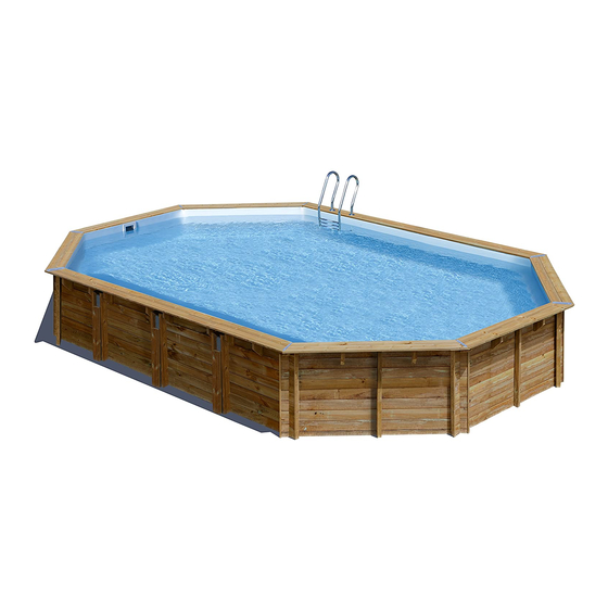
- Page 1 Instruction manual Ref. KWOV436 8 panels 4,36 x 3,36 x H 1,19 m Ref. KWOV551 8 panels 5,51 x 3,51 x H 1,19 m Ref. KWOV637 8 panels 6,37 x 4,12 x H 1,33 m www.gre.es Take the reference number of your pool into account when you do the assembly.
- Page 3 ATTENTION! Carefully read this information and keep it for later consultations. Congratulations on your choice. The model you have chosen has been especially designed for simple and rapid installation, but some precaution is necessary for the good use of your pool. Before starting with the installation and assembly of your pool, consider the current local regulation about on ground and in ground pools.
- Page 4 Any reclamation against guarantee should be made by pool). an online declaration, via with GRE Postvent Department, You should keep the label with the serial number of the together with receipt of purchase. liner that is on the product and on its packaging. This You may be asked for photographs to justify the claim.
- Page 5 BEFORE ASSEMBLY STORAGE PRECAUTIONS IN GROUND POOLS While the pool is disassembled, it is sensitive to variations AND SPECIFIC REGULATIONS of temperature and humidity. Therefore, certain precautions For on ground pools, we recommend protecting should be taken for storage. access to the pool by one standardized protection When you receive the packets, store the pieces of wood element.
- Page 6 Learn about wood WOOD: A LIVING MATERIAL Wood is a natural product, the fissures visible on the edges of the wood are completely normal and do not modify the resistance characteristics of the same. Wood is always a malleable material (from 3% to 4% of dimensional variations) with humidity and temperature oscillations. Therefore, small cracks can appear and in order to limit later deformations, the technical criteria have been respected regarding the design, the choice of sections, and of packaging and the fixing methods.
-
Page 7: Table Of Contents
• 1 screwdriver (with Torx point No. Location of the refilling fitting T15, T20, T25) Fixing of the liner fixing profiles ref. KWOV436 • 1 drill with bits for wood Ø4, Ø6 Fixing of the liner fixing profiles ref. KWOV551 and Ø10, for concrete Ø10 and for... -
Page 8: Previsions
Previsions... 1 FILTER GROUP The filter group and especially the electric pump should necessarily be located at a distance of at least 3.5 metres from the bowl (electricity regulation NFC-100). 2 WATER EVACUATION: Maintenance and wintering of the filter requires water evacuation. The evacuation should be foreseen when installing the filter group. - Page 9 Ground layout 4530 mm Ref. KWOV436 50 cm Figure 3 Surrounding area 25 cm 4024 mm 90° Ref. KWOV551 50 cm Interior dimensions Figure 3 5524 mm 50 cm Concrete slab: Provide for an additional 25 cm in length and 50 cm in width.
-
Page 10: Preparing The Land
The concrete slab is not included. Dosing 350 kg/m3 (standardized type C125 430). Ref. KWOV436 L: 4,53 x W: 4,03 x H: 0,10 m - 2,74 m of concrete. L: 5,53 x W: 4,03 x H: 0,15 m - 3,34 m of concrete. - Page 11 PARTIAL OR COMPLETELY IN-GROUND INSTALLATION According to the nature of the land, you should install a peripheral drainage and connect it to a decompression well. The well will be excavated before the construction of the pool to avoid that the excavations fill with water during the works. It should be near the pool, a few centimetres lower than the deepest point of the same and reach up to the surface.
- Page 12 Boards Ref. KWOV436 IDENTIFICATION OF THE BOARDS Figure 7 IDENTIFICATION DENOMINATION REFERENCIA Standard board L1500 - Cut D45°/G45° - V 778717 Standard board L2500 - Cut D45°/G45° - V 778724 Split board - L1500 - Cut D45°/G45° - V 778718...
- Page 13 Protective ground blanket Ref. KWOV436 After having done the installation and preparation of the ground you can start with assembling the pool. Start by laying the protective blanket, which should be cut from the roll included*, on the floor. Scrupulously respect the indicated measures to cut the roll.
- Page 14 Boards Ref. KWOV551 IDENTIFICATION OF THE BOARDS Figure 7 IDENTIFICATION DENOMINATION REFERENCE Standard board L1500 - Cut D45°/G45° - V 778717 Standard board L3500 - Cut D45°/G45° - V 784648 Split board - L1500 - Cut D45°/G45° - V 778718 Board with cut-out for the lower part of the skimmer - L1500 - Cut 778719 D45°/G45°...
- Page 15 Protective ground blanket Ref. KWOV551 After having done the installation and preparation of the ground you can start with assembling the pool. Start by laying the protective blanket, which should be cut from the roll included*, on the floor. Scrupulously respect the indicated measures to cut the roll. •...
- Page 16 Boards Ref. KWOV637 IDENTIFICATION OF THE BOARDS Figure 7 IDENTIFICATION DENOMINATION REFERENCE Standard board L1750 - Cut D45°/G45° - V 779959 Standard board L4000 - Cut D45°/G45° - V 784731 Split board - L1750 - Corte D45°/G45° - V 779964 Board with cut-out for the lower part of the skimmer - L1750 - Cut 779961 D45°/G45°...
- Page 17 Protective ground blanket Ref. KWOV637 After having done the installation and preparation of the ground you can start with assembling the pool. Start by laying the protective blanket, which should be cut from the roll included*, on the floor. Scrupulously respect the indicated measures to cut the roll. •...
- Page 18 Assembly of the structure Ref. KWOV436 Figure 11 ABOVE GROUND INSTALLATION LAYOUT OF THE BOARDS Prepare the boards «as a trial», forming the silhouette of the pool. INSTALLATION OF THE FIRST LAYER OF BOARDS as shown by figure 12.
- Page 19 2ND LAYER OF BOARDS • Install the second layer of boards as shown in figure 14. • There is a wooden wedge in the structure packet to correctly assemble the boards. • Never directly hit against the boards.. You would damage the pegs and would weaken the structure.
- Page 20 Ref. KWOV436 LAYOUT OF THE COLUMNS support columns installed with drill after laying the second layer of boards. Tighten the columns well around the entire layer of boards. Figure 15 Figure 16 Figure 17 • • Position the columns • Vertically drill the layer •...
- Page 21 SPECIFIC BOARDS: Refilling fitting: • Place the specific board for the refilling fitting situating the larger diameter on the external side of the pool. nozzle skimmer location location larger diameter on exterior board or 7 board Figure 19 Skimmer: Place the specific boards for the skimmer facing the prevailing winds.
- Page 22 Assembly of the structure Ref. KWOV551 Figure 11 ABOVE GROUND INSTALLATION LAYOUT OF THE BOARDS Prepare the boards «as a trial», forming the silhouette of the pool. INSTALLATION OF THE FIRST LAYER OF BOARDS as shown by figure 12. • Build the first layer placing boards Figure 12 •...
- Page 23 2ND LAYER OF BOARDS • Install the second layer of boards as shown in figure 14. • There is a wooden wedge in the structure packet to correctly assemble the boards. • Never directly hit against the boards.. You would damage the pegs and would weaken the structure.
- Page 24 Ref. KWOV551 LAYOUT OF THE COLUMNS support columns installed with drill after laying the second layer of boards. Tighten the columns well around the entire layer of boards. Figure 15 Figure 16 Figure 17 • Position the columns at • Vertically drill the layer •...
- Page 25 SPECIFIC BOARDS: Refilling fitting: • Place the specific board for the refilling fitting situating the larger diameter on the external side of the pool. skimmer location nozzle location larger diameter on exterior board Figure 19 Skimmer: • Place the specific boards for the skimmer facing the prevailing winds.
- Page 26 Assembly of the structure Ref. KWOV637 Figure 11 ABOVE GROUND INSTALLATION LAYOUT OF THE BOARDS Prepare the boards «as a trial», forming the silhouette of the pool. INSTALLATION OF THE FIRST LAYER OF BOARDS Build the first layer placing boards as shown by figure 12.
- Page 27 2ND LAYER OF BOARDS • Install the second layer of boards as shown in figure 13. • There is a wooden wedge in the structure packet to correctly assemble the boards. • Never directly hit against the boards.. You would damage the pegs and would weaken the structure.
- Page 28 Ref. KWOV637 LAYOUT OF THE COLUMNS support columns installed with drill after laying the second layer of boards. Tighten the columns well around the entire layer of boards. Figure 14 Figure 15 Figure 16 Figure 17 • •osition the columns at •...
- Page 29 SPECIFIC BOARDS: Refilling fitting: • Place the specific board for the refilling fitting situating the larger diameter on the external side of the pool. skimmer location nozzle larger diameter location on exterior board Figure 19 Skimmer: • Place the specific boards for the skimmer facing the prevailing winds.
-
Page 30: Wooden Blocks, Reinforcements And Trimmings
Systematically check that the upper part of the wooden block. • Make sure that the head of the screw is level with the surface of the wood. baguettes sans feutre de paroi Ref. KWOV436 Ref. KWOV551 Ref. KWOV637 The wooden blocks are designed to support the edges. - Page 31 TRIMMINGS L • Position the L trimming on the ends of the boards. • Cut off the excess part of the trimming according to the height of the pool if necessary (figure 21). • Fix trimming L using 3 screws 4 x 60 uniformly distributed over the height of the piece (figure 22). Figure 21 Figure 22 This finishes the assembly of the structure.
-
Page 32: Wooden Stepladder
Wooden ladder Check the drawings at the end of this manual. The wooden stepladder is included for access to the pool. Do not use for anything else. Assemble the wooden stepladder and use it as a template to define the separation of the wooden blocks that support it. In the case that the pool ahs an elongated shape, the stepladder will be positioned on a small side. - Page 33 88 mm For safety reasons, you should Admitted maximum weight = 150 kgs. respect these dimensions whatever 235 mm ...
-
Page 34: Protective Wall Blanket
Protective wall blanket There are two possibilities to install the wall protecting blanket TWO FACED ADHESIVE TAPE (NOT INCLUDED) • Stick the two-faced adhesive tape panel by panel, aligning it with the upper part of the top boards (figure 27). If the wood is slightly humid and dusty, it can be smoothened using sandpaper to facilitate adherence. -
Page 35: Installation Of The Liner
Liner profiles INSTALLATION OF THE LINER HOOKING PROFILE Fixing the pre-cut Ref. KWOV436 Fixing the profile by 5 screws profile by 2 screws Do not previously drill the boards. Figure 31 ADJUSTMENT AND FIXING OF THE PROFILES Position the profile trying to place it at 20 mm from the axis. - Page 36 Liner profiles INSTALLATION OF THE LINER HOOKING PROFILE Fixing the pre-cut Ref. KWOV551 Fixing the profile by 5 screws profile by 2 screws Do not previously drill the boards. Figure 31 ADJUSTMENT AND FIXING OF THE PROFILES Position the profile trying to place it at 20 mm from the axis. ...
- Page 37 Liner profiles INSTALLATION OF THE LINER HOOKING PROFILE Fixing the pre-cut Ref. KWOV637 Fixing the profile by 5 screws profile by 3 screws Do not previously drill the boards. Figure 31 ADJUSTMENT AND FIXING OF THE PROFILES Position the profile trying to place it at 20 mm from the axis. ...
- Page 38 Previous check before installing the liner • Clean the inside structure of the pool (grains of sand, screws...) use a vacuum cleaner if necessary. • Check that the skimmer seal is in its place. • Position the trap door inside the skimmer. •...
- Page 39 To move the already installed liner, slide it along the profile. If this is difficult the liner can be removed by lifting it to not damage it. Make sure that the liner is well positioned both on the floor as on the walls, uniformly adjust the tension of the same (with your foot, push the liner by its angles towards the corners of the walls) (figure 38).
- Page 40 Landfill (for fully or partially in-ground pools) In fully or partially in-ground pools, a gravel landfill is necessary to favour perfect draining. The landfill of a pool can seem a mere formality, because a first sight there are no special technical difficulties. Nevertheless, it is a more delicate operation than what it seems, for which certain precautions are necessary.
- Page 41 INFORMATION The drainage allows the continuous evacuation of water, at the foot of the pool and, therefore limits the rising of water by capillary attraction towards the upper part of the works, where air and soil interact to produce fungi or rot (lower diagram) The absence of draining causes water to ascend by capillary action that can be important and permanent, which favours the attacks of air / water interaction (lower diagram).
- Page 42 REFILLING FITTING REFILLING FITTING Install the • The liner should be well-tensed. Continue with the installation until the water reaches 10 filter before cm below the refilling fitting. continuing with cutting Cutting of the liner: the liner. • From outside of the pool, locate the centre of the nozzle and mark it using a cutter. •...
- Page 43 SKIMMER Figure 44 • The liner should be well-tensed. Continue with the installation until the water reaches 10 cm below the skimmer. • Before continuing, make sure that the skimmer flap is well positioned. • Mark the position of the fixing screws on the liner with a felt-tip pen. •...
- Page 44 Filter ASSEMBLY SUGGESTIONS: • The filter should be located at least 3.50 m from the pool. The following diagrams explain the movement direction of the water. Check the manual that comes with the filter group for the assembly instructions. The multi-directional flap determines the flow direction.
-
Page 45: Land-Filling
All the threaded connections should be assembled with the watertight Teflon The installation of all tape included (represented in green in the following diagrams), except the the electrical systems connection with O rings. The Teflon should be wound round the thread in a counter should comply with the clockwise direction. - Page 46 • La ubicación de los tornillos esta indicada en el siguiente esquema. PIECE UNDER THE EDGES • Position the pieces of wood under the edges at the angles and fix them with 4 screws (4x40). Reference KWOV436 does not include «corner trimmings».
-
Page 47: Edges Ref. Kwov551
PLAYAS Ref. KWOV551 EDGES The edge consists of 2 pieces, an inside one and an outside one. Check the drawings at the end of this manual. PREPARATION • Before fixing the edge, position all the pieces as a trial, checking the installation drawings at the end of the manual, without screwing them, to uniformly distribute the sets. -
Page 48: Edges Ref. Kwov637
PLAYAS Ref. KWOV637 EDGES The edge consists of 2 pieces, an inside one and an outside one. Check the drawings at the end of this manual. PREPARATION • Before fixing the edge, position all the pieces as a trial, checking the installation drawings at the end of the manual, without screwing them, to uniformly distribute the sets. - Page 49 Stainless steel ladder Do not use the stepladder for other needs different to those indicated in this manual. Admitted maximum weight: 150 kg. Figure 45 Figure 46 • Assemble the upper handrail and lower introducing one into the other (figure 39). Fix the steps into the handrails using the bolts , the washers...
-
Page 50: Putting Into Service
Putting into service During the first use, you should wash the filter (check the filer system maintenance). Filtering is a mechanical treatment that allows cleaning the pool water by means of eliminating the impurities and contaminating particles. The hydraulic circuit and water purifying group is an essential element for the optimal operation of the filtering system. The filtering system should be coherent: The filter dimensions should be proportionate to the volume of water in the pool and to the pump performance. - Page 51 Maintenance of the filtering system CLEANING THE FILTER Perform this procedure each time you need to clean the filter. When the pressure increases 0.2 bar regarding the starting pressure you need to clean as follows. Make sure that you have correctly installed the emptying tube (not included) in the collector of the multi-directional flap, so that it allows water evacuation when the sand or filer is cleaned.
-
Page 52: Sand Filter
Sand Filter This is the oldest of filtering systems. The filtered water passes through the sand (calibrated silicon) that retains all impurities. This type of filter is equipped with a multi-directional flap that allows easy manipulations and cleaning. DIFFERENT POSITIONS OF THE MULTI-DIRECTIONAL FLAP (4 OR 6)*: When you perform changes the position of the multi-directional flap that pump should always be stopped, without risking seriously damaging the filter and cancelling the guarantee. -
Page 53: Wintering
4. EMPTYING POSITION / DRAIN (OR WASTE): Position to evacuate the water or for emptying the pool. In this case, the water does not pass through the filter, it goes directly to the drain. Skimmer 5. CLOSED POSITION: This position does not allow the water to pass and is used to put the pool into complete wintering when the filtering stops. Skimmer 6. - Page 54 MAINTENANCE AND USE RESPECT THE ENVIRONMENT DO NOT TAKE APART THE POOL UNLESS IT IS STRICTLY NECESSARY. IF YOU DO SO, PLEASE REUSE THE WATER. WATER IS A SCARCE GOOD. - Switch on the filter system once a day in to insure a complete water volume renewal and never do it when somebody is in the pool (see filter manual).
- Page 55 - Chlorine treatments: Consist in increasing the chlorine level until approximatively 20 ppm to eliminate germs and seaweeds. This process has to be done only when the pool water comes from rivers or ponds, … or if it stayed a long time without any treatments. - Checking: Check at least once a week the chlorine levels (use a chlorine and pH analyser).
- Page 56 Installation drawing Ref. KWOV436 Dimensions in mm IDENTIFICATION DENOMINATION REF. ACCORDING TO MODEL Edge L2390- Cut D 22.5º / G 22.5º 778482 ...
- Page 57 You should respect all these Ref. KWOV436 dimensions to perfectly adjust the liner and the Dimensions in mm Renfort 68x46 edges. 1500 Corbelet 1252 3024 3116 Wooden Large blocks reinforcements...
- Page 58 Installation drawing Ref. KWOV551 Dimensions in mm 3505 Répère Désignation Référence Quantité Margelle Intérieure L3331 - Coupe D22.5° / G22.5° - V 784652 Margelle Extérieure L3452 - Coupe D22.5° / G22.5° - V 784653 Margelle Intérieure L1331 - Coupe D22.5° / G22.5° - V 784650 Margelle Extérieure L1452 - Coupe D22.5°...
- Page 59 You should respect all these Ref. KWOV551 dimensions to perfectly adjust the liner and the Dimensions in mm edges. 1500 1252 3024 3116 Large Wooden Small reinforcements blocks reinforcements...
- Page 60 Installation drawing Ref. KWOV637 Dimensions in mm 4109 IDENTIFICATION DENOMINATION REF. ACCORDING TO MODEL Répère Désignation Référence Quantité Inside edge L1581- Cut D 22.5º / G 22.5º 784733 Margelle Intérieure L1581 - Coupe D22.5° / G22.5° - V 784733 Outside edge L1702- Cut D 22.5º / G 22.5º 784734 Margelle Extérieure L1702 - Coupe D22.5°...
- Page 61 You should respect all these Ref. KWOV637 dimensions to perfectly adjust the liner and the Dimensions in mm edges. 1750 1502 3627 3719 Large Wooden Small reinforcements blocks reinforcements...
- Page 62 The equipment should be connected to a voltage, with earth connection, protected by a residual current device (RCD) having a rated residual operating current not exceeding 30 mA. Read the instructions carefully and keep for future reference. IF YOU HAVE ANY PROBLEM, ..¡CONTACT US! CONTACT TELEPHONE: +34 946 741 844 e-mail: aacha@gre.es - web: www.gre.es...
- Page 63 CUSTOMER CARE SERVICE MANUFACTURAS GRE, S.A. Aritz bidea nº 57, Trobika Auzotegia - Apartado 69, 48100 Munguía (Vizcaya) - España Tel: (34) 946 741 844 - Fax: (34) 946 740 321 e-mail: aacha@gre.es - web: www.gre.es...
- Page 64 DISTRIBUTED BY MANUFACTURAS GRE S.A. ARITZ BIDEA 57, BELAKO INDUSTRIALDEA 48100 MUNGIA (VIZCAYA) ESPAÑA Tlf. 946 741 116 Nº REG. IND.: 48-06762 MADE IN EUROPA www.gre.es...
Need help?
Do you have a question about the KWOV436 and is the answer not in the manual?
Questions and answers