Table of Contents
Advertisement
Quick Links
Advertisement
Table of Contents

Related Manuals for Janome Magnolia 7312


Summary of Contents for Janome Magnolia 7312
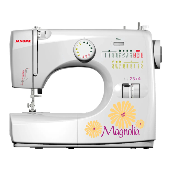
- Page 1 SERVICE MANUAL MODEL 7312...
-
Page 2: Table Of Contents
TABLE OF CONTENTS PAGE 0. Dismantling the rear cover 1. Upper shaft end play 2. Cam stack gear mesh 3. Needle bar height 4. Shuttle timing 5. Needle position 6. Zeroing the needle 7. Feed dog height 8. Feed lifting cam 9. -
Page 3: Dismantling The Rear Cover
0. DISMANTLING THE REAR COVER 1. Unscrew the screws: a. b. c. d. e. f. 2. Open face cover and shuttle cover and pull out the spool p i n s . 3. Remove the rear cover in direction of arrow. spool pins face cover shuttle cover... -
Page 4: Upper Shaft End Play
1. UPPER SHAFT END PLAY (ALL MODELS) Check : 1. Hold clamp of stop motion by hand , check play that push in and pull out on upper shaft. According with above method, recheck upper shaft play at any point during the revolution. Adjustment : 1. -
Page 5: Cam Stack Gear Mesh
2. CAM STACK GEAR MESH (ALL MODELS) Check : 1. Remove rear cover. 2. Place machine in straight stitch. 3. Check at three different points in a full revolution, zero or very slight play is acceptable. Adjustment : 1. Loosen set screw (E). 2. -
Page 6: Needle Bar Height
3. NEEDLE BAR HEIGHT (ALL MODELS) Check : 1. Take out bobbin case and shuttle race cap. 2. Select zigzag and max , width stitch. 3. Rotate hand wheel until needle is full down in right position. 4. Then , slowly raise needle bar to (a) position , the distance shall be 1 mm. -
Page 7: Shuttle Timing
4. SHUTTLE TIMING (ALL MODELS) Check : 1. Take out bobbin case and shuttle race cap. 2. Select zigzag and max, width stitch. 3. Rotate hand wheel until needle is full down in the left needle position. 4. The point of shuttle shall be 3.2 mm to the left of needle. -
Page 8: Needle Position
5 mm 5. NEEDLE POSITION (ALL MODELS) Check : 1. Set machine for zigzag max, width. 2. Turn machine by hand and observe needle as it enters the needle plate , left and right entry should be equal distance from the edge of the needle plate hole (A). -
Page 9: Zeroing The Needle
6. ZEROING THE NEEDLE (ALL MODELS) Check : 1. Select straight stitch position. 2. Sewing a line straight stitch. 3. Shall be no or minimul movement below 0.3 mm. Adjustment : 1. Remove rear cover. 2. Select straight stitch position. 3. -
Page 10: Feed Dog Height
7. FEED DOG HEIGHT (ALL MODELS) Check : 1. Bring feed dog to it's highest point. 2. The top or the feed dog should be 0.8-1.0 mm above the surface of the needle plate. Adjustment : 1. Remove rear cover. 2. -
Page 11: Feed Lifting Cam
8. FEED LIFTING CAM (ALL MODELS) Check : 1. Turn the hand wheel to make needle point position about above needle plate. 2. At this time, teeth of feed dog are required to keep same height with that of needle plate surface. -
Page 12: Stretch Stitch Selector Cam 1
9. STRETCH STITCH SELECTOR CAM MODEL : JANOME 7312 Check : 1. Set pattern selector dial at (A) and (D). 2. Sewing (A) and (D) pattern. 3. Sewn-out look (A) and (D), stitch length must be same. Adjustment : 1. Remove rear cover. -
Page 13: Belt Adjusting
10. V BELT ADJUSTING (ALL MODELS) Check : 1. Remove rear cover and front cover. 2. Belt about parallel of two side during pressure 300g use spring gauge measured. Adjustment : 1. Remove rear cover and front cover . 2. Loosen two screw of motor (B). 3. -
Page 14: Bobbin Winder
11. BOBBIN WINDER (ALL MODELS) Clamp stop motion washer Check: 1. loosen clamp stop motion large screw (A) and run machine. 2. Hand wheel (C) should rotate freely without needle bar moving up or down. 3. Tighten clamp stop motion large screw (A) and sew over heavy seam (6 ply denim or equivalent). - Page 15 0.8~1.5mm...
-
Page 16: Take-Up Spring Replacement And Setting
12.TAKE-UP SPRING REPLACEMENT AND SETTING (ALL MODELS) Check : 1. Open face cover. 2. Check to this "take-up spring", in normal it should touch to (A) , and take-up spring should be 1~1.5 mm (B). 3. When this spring in operation (Lift in arrow direction) tension be 6g~12g. -
Page 17: Bobbin Case Tension
13. BOBBIN CASE TENSION (ALL MODELS) Adjustment : 1. Remove bobbin case. 2. Insert a fully wound bobbin in case and thread normally. 3. Remove shuttle race cap. 4. Tie race cap to thread from bobbin case. 5. Hold bobbin case upside down without touching tension spring. -
Page 18: Stretch Stitch Sewing
14. STRETCH STITCH SEWING MODEL: JANOME 7312 Check : 1. Set the pattern selector at ( 2. Sewn-out patterns look not like (a) patterns are too far and (c) patterns are overlap. Adjustment : 1. Remove rear cover . 2. Loosen nut (F). -
Page 19: Electrical Connections
16. ELECTRICAL CONNECTIONS Switch Light Motor 120V (FDM TYPE) Motor 230V (FDM TYPE)
Need help?
Do you have a question about the Magnolia 7312 and is the answer not in the manual?
Questions and answers