Table of Contents
Advertisement
Available languages
Available languages
Advertisement
Table of Contents

Related Manuals for ESAB EPP-362


Summary of Contents for ESAB EPP-362
- Page 1 EPP-362 Plasma Power Source Instruction Manual 0558011594 07/2013...
-
Page 2: User Responsibility
Be sure thIs InforMatIon reaches the operator. You can get extra copIes through Your supplIer. cautIon these InstructIons are for experienced operators. If you are not fully familiar with the principles of operation and safe practices for arc welding and cutting equipment, we urge you to read our booklet, “precautions and safe practices for arc Welding, cutting, and gouging,”... -
Page 3: Table Of Contents
EPP-362 J1 (RAS) - Interface Diagram........ - Page 4 taBle of contents...
-
Page 5: Safety Precautions
sectIon 1 safetY precautIons safety precautions safety - english WarnIng: These Safety Precautions are fIres anD explosIons -- heat from for your protection. They summarize pre- flames and arcs can start fires. hot cautionary information from the references slag or sparks can also cause fires and listed in Additional Safety Information sec- explosions. - Page 6 sectIon 1 safetY precautIons 1. Be sure the power source frame (chassis) is con- 3. Welders should use the following procedures to nected to the ground system of the input power. minimize exposure to EMF: 2. Connect the workpiece to a good electrical A.
- Page 7 sectIon 1 safetY precautIons 5. WarnIng: this product, when used for welding 1. Always have qualified personnel perform the instal- or cutting, produces fumes or gases lation, troubleshooting, and maintenance work. which contain chemicals known to Do not perform any electrical work unless you are the state of california to cause birth qualified to perform such work.
- Page 8 sectIon 1 safetY precautIons 5. AWS C5.5 - "Recommended Practices for Gas Tung- sten Arc Welding“ 6. AWS C5.6 - "Recommended Practices for Gas Metal Arc Welding"“ 7. AWS SP - "Safe Practices" - Reprint, Welding Hand- book. 8. ANSI/AWS F4.1, "Recommended Safe Practices for Welding and Cutting of Containers That Have Held Hazardous Substances."...
-
Page 9: Safety - Spanish
seccIon 1 segurIDaD safety - spanish La escoria puede estar caliente y desprenderse con velocidad. Personas cercanas deberán usar gafas aDVertencIa: Estas Precauciones de Se- de seguridad y careta protectora. guridad son para su protección. Ellas hacen resumen de información proveniente de las fuego Y explosIones -- el calor de referencias listadas en la sección "Información Adi- las flamas y el arco pueden ocacionar... - Page 10 seccIon 1 segurIDaD 1. Asegúrese de que el chasis de la fuente de poder 3. Los soldadores deberán usar los siguientes proced- esté conectado a tierra através del sistema de imientos para minimizar exponerse al EMF: electricidad primario. 2. Conecte la pieza de trabajo a un buen sistema de A.
- Page 11 seccIon 1 segurIDaD 5. aDVertencIa-- este producto cuando se uti- 1. Siempre tenga personal cualificado para efec- liza para soldaduras o cortes, tuar l a instalación, diagnóstico, y mantenimiento produce humos o gases, los del equipo. No ejecute ningún trabajo eléctrico a cuales contienen químicos menos que usted esté...
- Page 12 seccIon 1 segurIDaD sIgnIfIcaDo De los sIMBolos -- según usted avanza en la lectura de este folleto: los símbolos sig- nifican ¡atención! ¡esté alerta! se trata de su seguridad. significa riesgo inmediato que, de no ser evadido, puede resultar inmediatamente en serio daño personal o la muerte.
-
Page 13: Safety - French
sectIon 1 sÉcurItÉ safety - french IncenDIes et explosIons -- la chaleur provenant des flammes ou de aVertIsseMent : Ces règles de sécurité l'arc peut provoquer un incendie. le ont pour but d'assurer votre protection. Ils laitier incandescent ou les étincelles récapitulent les informations de précaution provenant des références dans la section peuvent également provoquer un... - Page 14 sectIon 1 sÉcurItÉ 1. Assurez-vous que le châssis de la source 3. Les soudeurs doivent suivre les procédures suivantes d'alimentation est branché au système de mise à pour minimiser l'exposition aux champs électriques la terre de l'alimentation d'entrée. et magnétiques : 2.
- Page 15 sectIon 1 sÉcurItÉ 5. aVertIsseMent : ce produit, lorsqu'il est utilisé entretIen De l'ÉQuIpeMent -- un équipe- dans une opération de soudage ou de ment entretenu de façon défectueuse ou coupage, dégage des vapeurs ou des inadéquate peut causer des blessures gaz contenant des chimiques consid- graves ou mortelles.
- Page 16 sectIon 1 sÉcurItÉ sIgnIfIcatIon Des sYMBoles ce symbole, utilisé partout dans ce manuel, signifie "attention" ! soyez vigilant ! Votre sécurité est en jeu. Danger signifie un danger immédiat. la situation peut entraîner des blessures graves ou mortelles. aVertIsseMent signifie un danger potentiel qui peut entraîner des blessures graves ou mortelles.
-
Page 17: Description
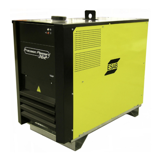
Description The EPP-362 power source is designed for mechanized plasma cutting and marking applications. It can be used with other ESAB products such as the PT-36 torch along with the m3 gas interface, a computerized gas regulation and switching system. -
Page 18: Dimensions
sectIon 2 DescrIptIon Dimensions 23.75” 47.25” (603.25 mm) (1200 mm) 40.75” (1035 mm) -
Page 19: Installation
sectIon 3 InstallatIon Installation general faIlure to folloW InstructIons coulD leaD to Death, In- JurY or DaMageD propertY. folloW these InstructIons WarnIng to preVent InJurY or propertY DaMage. You Must coM- plY WIth local, state anD natIonal electrIcal anD safetY coDes. -
Page 20: Input Power Connection
sectIon 3 InstallatIon Input power connection electrIc shocK can KIll! WarnIng proVIDe MaxIMuM protectIon agaInst electrIcal shocK. Before anY connectIons are MaDe InsIDe the MachIne, open the lIne Wall DIsconnect sWItch to turn poWer off. 3.4.1 primary power Three-phase input power must be provided from a line (wall) disconnect switch that contains fuses or circuit breakers in accordance to local or state regulations. - Page 21 sectIon 3 InstallatIon 3.4.2 Input conductors • Customer supplied • May consist either of heavy rubber covered copper conductors (three power and one ground) or run in solid or flexible conduit. • Sized according to the chart. 3.4.3 Input connection procedure IMproper grounDIng can result In Death or InJurY.
-
Page 22: Coolant Connection Procedure
With the torch connected, fill the reservoir with the specially formulated torch coolant (approx 4 gallons). Do not use regular anti-freeze solutions, such as for an automobile, as the additives will harm the pump and torch. ESAB P/N 0558004297 is recommended for service down to 12° F (-11° C). ESAB P/N 156F05 is recommended for service below 12°... -
Page 23: Delivery Pressure Adjustment
sectIon 3 InstallatIon Delivery pressure adjustment Delivery pressure is controlled by the relief valve mounted next to the pump in the tank compartment. Turn- ing the pressure adjustment screw clockwise increases pressure on the spring and raises the delivery pressure. Turning it counterclockwise reduces pressure on the spring and reduces the delivery pressure. -
Page 24: Output Connections
sectIon 3 InstallatIon output connections electrIc shocK can KIll! Dangerous Voltage anD current! anY tIMe WorKIng arounD a plasMa poWer source WIth coVers reMoVeD: WarnIng • DIsconnect poWer source at the lIne (Wall) DIsconnect. • haVe a QualIfIeD person checK the output Bus Bars (posItIVe anD negatIVe) WIth a VoltMeter. - Page 25 sectIon 3 InstallatIon 3.7.2 output connection procedure 1. Open access panel on the lower front of the power source by removing four M6 screws. 2. Thread output cables through the openings at the bottom of the power source immediately behind the front panel.
-
Page 26: Interface Cable Connectors
sectIon 3 InstallatIon Interface cable connectors can connector This is the CAN communication bus connector. The cable from this connector is tied to the CNC/process controller. J1 (ras) This is a connector for interfacing with Remote Arc Starter (RAS) unit. The cable from this connector carries signals such as: Mark Mode and Hi-Frequency ON. - Page 27 sectIon 3 InstallatIon 3.8.1 J1 (ras) Interface cable 3.8.2 can cables...
- Page 28 sectIon 3 InstallatIon 3.8.3 analog Interface cable...
-
Page 29: Operation
Dangerous Voltages anD current! electrIc shocK can KIll! WarnIng Before operatIon, ensure InstallatIon anD grounDIng pro- ceDures haVe Been folloWeD. Do not operate thIs eQuIp- Ment WIth coVers reMoVeD. epp-362 Block Diagram 1 ~ T2 200/230/380/ Input Fuse 400/460/575V... - Page 30 4 operatIon 4.1.1 epp-362 coolant flow Diagram As soon as the power source is supplied with input power, the coolant pump motor turns ON. Coolant pumps out to the torch and returns back to the coolant tank through the radiators, filter, flow sensor, and IGBTs cold plate respectively.
-
Page 31: Display Panel
sectIon 4 operatIon Display panel a - power light This indicator illuminates when input power is applied to the power supply. B - fault light Whenever there is a fault, this indicator illuminates. This may stay ON continuously or flash with 50% ON/OFF intervals depending on the type of fault. -
Page 32: Modes Of Operation
sectIon 4 operatIon Modes of operation Plasma unit can be operated in Cutting Mode or Marking Mode. The command to operate the machine in Cut- ting or Marking mode can be received from the CNC or Process controller through CAN (digital) communication or through analog communication. -
Page 33: Epp-362 J1 (Ras) - Interface Diagram
4 operatIon epp-362 J1 (ras) - Interface Diagram... -
Page 34: Sequence Of Operation
The EPP-362 has no power switch installed in the unit. The wall breaker is the power disconnect for this power supply. Once the wall breaker is closed, the following events occur: 1. Power is applied to the control transformer T2. This supplies power to the circuit boards - PCB1 the Con- trol board and PCB2 the Driver board. - Page 35 7. After the 5 minutes timer timed out, main fan turns off and K1 opens. Now, if a start signal is sent, the EPP-362 will perform the sequence of operations - steps 1 through 6. In case of MARKING, CNC/Process Controller will send the marking mode ON signal to power source via CAN Communication.
- Page 36 sectIon 4 operatIon...
-
Page 37: Maintenance
sectIon 5 MaIntenance Maintenance general electrIc shocK can KIll! WarnIng shut off poWer at the lIne (Wall) DIsconnect Before at- teMptIng anY MaIntenance. eYe haZarD When usIng coMpresseD aIr to clean. WarnIng • Wear approved eye protection with side shields when cleaning the power source. - Page 38 sectIon 5 MaIntenance flow sensor RotorFlow Sensor is used to monitor the flow rate of the coolant. Operation: The rotor reacts to turbulence, pulsation, entrained air, and other flow anomalies induced in the flow stream by other process hardware. For optimum performance, install RotorFlow units where nominal flow condi- tions exist, with ports located at the top.
- Page 39 CNC/Process controller by the power supply through CAN communication. THE INFORMATION CONTAINED IN THIS DRAWING IS THE SOLE PROPERTY 411 S. Ebenez OF ESAB WELDING & CUTTING. ANY REPRODUCTION IN PART OR AS A Florence, SC WHOLE WITHOUT THE WRITTEN PERMISSION OF ESAB WELDING & CUTTING IS PROHIBITED.
- Page 40 sectIon 5 MaIntenance...
-
Page 41: Troubleshooting
sectIon 6 trouBleshootIng troubleshooting electrIc shocK can KIll! WarnIng Do not perMIt untraIneD persons to Inspect or repaIr thIs eQuIpMent. electrIcal WorK Must Be perforMeD BY an experIenceD electrIcIan. stop work immediately if power source does not work properly. cautIon have only trained personnel investigate the cause. -
Page 42: Help Codes
200 msec. satisfy the threshold limit with in specified time. Check the consumables, distance between torch and plate. If this error activates every time please contact ESAB’s service department. AMBIENT TEMP Ambient temperature exceeded 75° C in The thermister on the Control Board (PCB1) has detected tem- control enclosure. -
Page 43: Help Codes Cont'd
This error board. requires the reset of power to the power supply. If the error isn’t cleared after the reset of power then contact ESAB’s service department. EEPROM FAILURE EEPROM Failed, replace Control Board. -
Page 44: Fault Isolation
sectIon 6 trouBleshootIng fault Isolation 6.3.1 fan not Working problem possible cause action This is normal when unit is in idle None mode for more than 5 minutes. Broken or disconnected wire in fan Repair wire. motor circuit. Fan does not turn ON Faulty fan(s) Replace fans Check relay connection and/or replace... -
Page 45: Replacement Parts
To ensure proper operation, it is recommended that only genuine ESAB parts and products be used with this equipment. The use of non-ESAB parts may void your warranty. Replacement parts may be ordered from your ESAB Distributor. - Page 46 notes...
-
Page 47: Revision History
reVIsIon hIstorY Original release -... - Page 48 Welding & cutting products, florence, sc coMMunIcatIon guIDe - custoMer serVIces CUSTOMER SERVICE QUESTIONS: Telephone: (800)362-7080 / Fax: (800) 634-7548 Hours: 8:00 AM to 7:00 PM EST Order Entry Product Availability Pricing Order Information Returns ENGINEERING SERVICE: Telephone: (843) 664-4416 / Fax : (800) 446-5693...
Need help?
Do you have a question about the EPP-362 and is the answer not in the manual?
Questions and answers