Table of Contents
Advertisement
Quick Links
HM-60190-7
Closed Loop Stepping Motor and Driver Package
AR Series
DC power input Built-in Controller Type
USER MANUAL
Thank you for purchasing an Oriental Motor product.
This Operating Manual describes product handling procedures and safety precautions.
• Please read it thoroughly to ensure safe operation.
• Always keep the manual where it is readily available.
Advertisement
Chapters
Table of Contents
Troubleshooting

Related Manuals for Orientalmotor AR Series FLEX DC

Summary of Contents for Orientalmotor AR Series FLEX DC
-
Page 1: User Manual
HM-60190-7 Closed Loop Stepping Motor and Driver Package AR Series DC power input Built-in Controller Type USER MANUAL Thank you for purchasing an Oriental Motor product. This Operating Manual describes product handling procedures and safety precautions. • Please read it thoroughly to ensure safe operation. •... -
Page 2: Table Of Contents
1 Introduction 3 Operation type and setting Introduction ........... 8 Adjustment and setting ......60 1.1 Resolution............ 60 Operating Manuals for the AR Series ..9 1.2 Operating current......... 61 Overview of the product ......10 1.3 Standstill current .......... 61 System configuration ........12 1.4 Acceleration/deceleration rate and Safety precautions ........ - Page 3 4 Method of control via I/O 10 Detection of communication errors ..160 10.1 Communication errors ......160 10.2 Alarms and warnings ........ 160 Guidance ............ 106 11 Timing charts ..........161 Operation data ........... 108 Parameter ........... 109 6 Method of control via 3.1 Parameter list ..........109 industrial network 3.2 I/O parameter ..........110 3.3 Motor parameter ........
- Page 4 7 Inspection, troubleshooting and remedial actions Inspection ..........198 Alarms and warnings ........ 199 2.1 Alarms ............199 „ Alarm reset ............199 „ Alarm records ..........199 „ Alarm list ............200 2.2 Warnings ........... 204 „ Warning records ..........204 „ Warning list ............204 2.3 Communication errors ....... 205 „ Communication error records ......205 „ Communication error list ........205 Troubleshooting and remedial actions ... 206 8 Appendix Accessories (sold separately) ....
- Page 5 Specification Change of Driver Some specifications have been changed in this product. There are differences in data setting range, etc. between the product after the change and before the change. For the driver before the specification change, contact your nearest Oriental Motor sales office.
- Page 6 2. The upper limit of the alarm output has been changed The maximum speed for push-motion operation has been changed. If push-motion operation is started after setting higher speed than 30 r/min in the driver which is before the specification change, an operation data error alarm will generate. • Maximum speed for push-motion operation Before the specification change ...
- Page 7 1 Introduction This part explains the composition of the operating manuals, the product overview, specifications and safety standards as well as the name and function of each part and others. Table of contents 1 Introduction ........8 2 Operating Manuals for the AR Series ..........
-
Page 8: Introduction
Introduction 1 Introduction „ Before use Only qualified personnel should work with the product. Use the product correctly after thoroughly reading the section "5 Safety precautions" on p.13. The product described in this manual has been designed and manufactured for use in general industrial equipment. Do not use for any other purpose. -
Page 9: Introduction
2 Operating Manuals for the AR Series Operating manuals for the AR Series FLEX DC power input built-in controller type are listed below. The "USER MANUAL" does not come with the product. For details, contact your nearest Oriental Motor sales office or download from Oriental Motor website download page. -
Page 10: Overview Of The Product
The operation data and parameters can be set using the accessory OPX-2A (sold separately) or MEXE02, or via RS- 485 communication. Provide the OPX-2A or MEXE02 as necessary. „ Related products The AR Series FLEX DC power input built-in controller type can be used via various network when connecting to a network converter. Network converter... - Page 11 Overview of the product „ Function list Main functions • 2-sensor mode • Push-mode Return-to-home operation • 3-sensor mode • Data setting mode (Position preset) [Setting by parameters] • Positioning operation Operation function Starting method Motor operation Single-motion operation Data number selecting operation Linked-motion operation Direct positioning operation [Setting by operation data...
-
Page 12: System Configuration
System configuration 4 System configuration OPX-2A PC in which the MEXE02 (sold separately) has been installed Connect to CN6 or CN7 Master controller Connect when controlling The PC must be supplied by the the system via RS-485 customer. Use the communication communication. -
Page 13: Safety Precautions
Safety precautions 5 Safety precautions The precautions described below are intended to prevent danger or injury to the user and other personnel through safe, correct use of the product. Use the product only after carefully reading and fully understanding these instructions. Handling the product without observing the instructions that accompany a "Warning"... - Page 14 Safety precautions General • Do not use the motor and driver beyond its specifications. Doing so may result in injury or damage to equipment. • Keep your fingers and objects out of the openings in the motor and driver. Failure to do so may result in fire or injury.
- Page 15 Safety precautions „ Handling the battery Be sure to observe the following instructions when using the accessory battery (sold separately). Handling the battery without observing the instructions may cause the liquid leakage, heat generation and explosion, etc., which may result in injury or damage to equipment.
-
Page 16: Precautions For Use
Precautions for use 6 Precautions for use This section covers limitations and requirements the user should consider when using the product. • Always use the cable (supplied or accessory) to connect the motor and driver. Be sure to use the cable (supplied or accessory) to connect the motor and driver. In the following condition, an appropriate accessory cable must be purchased separately. - Page 17 Precautions for use • Rotation direction of the gear output shaft The relationship between the rotation direction of the motor shaft and that of the gear output shaft changes as follows, depending on the gear type and gear ratio. Rotation direction Type of gear Gear ratio (relative to the motor rotation direction)
-
Page 18: General Specifications
General specifications 7 General specifications Motor Driver IP65 (Excluding the motor mounting surface and connectors) Degree of protection IP10 IP20 (Double shaft type, models including "S" in the motor identification of motor name.) −10 to +50 °C (+14 to +122 °F) (non-freezing) ∗... -
Page 19: Ce Marking
CE Marking 8 CE Marking „ Low Voltage Directives Because the input power supply voltage of this product is 24 VDC/48 VDC, it is not subject to the Low Voltage Directive but install and connect this product as follows. This product is designed and manufactured to be installed within another device. Install the product in an enclosure. For the driver power supply, use a DC power supply with reinforced insulation on its primary and secondary sides. -
Page 20: Preparation
Preparation 9 Preparation This chapter explains the items you should check, as well as the name and function of each part. 9.1 Checking the product Verify that the items listed below are included. Report any missing or damaged items to the branch or sales office from which you purchased the product. -
Page 21: Combinations Of Motors And Drivers
Preparation 9.3 Combinations of motors and drivers • indicates A (single shaft), B (double shaft) or M (with electromagnetic brake). • For AR14S and AR15S , indicates A (single shaft) or B (double shaft). For geared type, indicates A (single shaft) or M (with electromagnetic brake). •... -
Page 22: Names And Functions Of Parts
Preparation 9.4 Names and functions of parts „ Driver RS-485 communication connectors (CN6/CN7) Function setting switches (SW3) POWER/ALARM LED C-DAT/C-ERR LED Address number setting switch (SW1) Data edit connector (CN3) Transmission rate setting switch (SW2) Battery connector (CN4) Output signal connector (CN9) Motor connector (CN2) Input signal connector (CN8) Electromagnetic brake terminals (CN1) - Page 23 Preparation Name Description Page − POWER LED (Green) This LED is lit while the power is input. This LED will blink when an alarm generates. It is possible to check the generated ALARM LED (Red) p.199 alarm by counting the number of times the LED blinks. This LED will blink or illuminate steadily when the driver is communicating with −...
- Page 24 Preparation „ Motor (Example: ARM66SMK) Protective Earth Terminal (M4) Motor Mounting holes (4 locations) Electromagnetic brake Output shaft Motor cable Pilot Electromagnetic brake cable −24− 1 Introduction...
-
Page 25: 2 Installation And
2 Installation and connection This part explains the installation method of the product, the mounting method of a load and the connection method as well as I/O signals. Table of contents 1 Installation ........26 3 Explanation of I/O signals ....39 Location for installation ...... -
Page 26: Installation
Installation 1 Installation This chapter explains the installation location and installation methods of the motor and driver, along with load installation. The installation and wiring methods in compliance with the EMC Directive are also explained. 1.1 Location for installation The motor and driver has been designed and manufactured to be installed within another device. Install them in a well-ventilated location that provides easy access for inspection. -
Page 27: Installing A Load
Installation 1.3 Installing a load When connecting a load to the motor, align the centers of the motor output shaft and load shaft. Flexible couplings are available as accessories. Note • When coupling the load to the motor, pay attention to the centering of the shafts, belt tension, parallelism of the pulleys, and so on. -
Page 28: Permissible Radial Load And Permissible Axial Load
Installation 1.4 Permissible radial load and permissible axial load Note • If the radial load or axial load exceeds the specified allowable value, repeated load applications may cause the bearing (ball bearings) or output shaft of the motor to undergo a fatigue failure. •... -
Page 29: Installing The Driver
Installation Permissible radial load [N (lb.)] Permissible axial Type Model Gear ratio Distance from the tip of motor output shaft [mm (in.)] load [N (lb.)] 0 (0) 5 (0.2) 10 (0.39) 15 (0.59) 20 (0.79) − AR24 100 (22) 135 (30) 175 (39) 250 (56) 140 (31) -
Page 30: Installing The Battery
Installation Removing from DIN rail Pull the DIN lever down until it locks using a flat tip screwdriver, and lift the bottom of the driver to remove it from the rail. Use force of about 10 to 20 N (2.2 to 4.5 lb.) to pull the DIN lever to lock it. Excessive force may damage the DIN lever. - Page 31 Installation „ Wiring the power supply cable and I/O signal cable Use a shielded cable for the power supply cable and I/O signal cable, and keep it as short as possible. To ground a shielded cable, use a metal cable clamp or similar device that will maintain contact with the entire circumference Shielded cable of the cable.
-
Page 32: Connection
Connection 2 Connection This chapter explains how to connect the motor, I/O signals and power supply to the driver, as well as grounding method. 2.1 Connection example (electromagnetic brake motor) Wiring the CN5/CN8/CN9 connector Button of the orange color Insert the lead wire while pushing the button of the orange color with a screwdriver. - Page 33 Connection „ Power supply current capacity Power supply current capacity Input power Model supply voltage Standard type Electromagnetic brake type − AR14 0.4 A or more − AR15 0.5 A or more 24 VDC±5% AR24 1.3 A or more 1.37 A or more AR26 AR46 1.72 A or more...
- Page 34 Connection „ Connecting to a current sink output circuit (NPN specifications) Controller Driver 12 to 24 VDC 10 mA or less OUT0 OUT1 OUT2 Output saturated OUT3 voltage 3 V max. OUT4 OUT5 OUT-COM 4.4 kΩ 1 kΩ 4.4 kΩ 1 kΩ...
- Page 35 Connection „ Connecting to a current source output circuit (PNP specifications) Controller Driver 12 to 24 VDC 10 mA or less OUT0 OUT1 OUT2 Output saturated OUT3 voltage 3 V max. OUT4 OUT5 OUT-COM 24 VDC 4.4 kΩ 1 kΩ 4.4 kΩ...
-
Page 36: Grounding The Motor And Driver
Connection 2.2 Grounding the motor and driver „ Grounding the motor Be sure to ground the Protective Earth Terminal of the motor. (It is no need to ground when the driver power supply voltage is 24 VDC.) Grounding wire: AWG18 (0.75 mm ) or more Tightening torque: 1.2 N·m (170 oz-in) When grounding, use a round terminal and secure it with a mounting screw with a... -
Page 37: Connecting The Rs-485 Communication Cable
Connection 2.4 Connecting the RS-485 communication cable Connect this cable if you want to control your product via RS-485 communication. Connect the RS-485 communication cable to CN6 or CN7 on the driver. You can use the vacant connectors to connect a different driver. A driver link cable is available as an accessory (sold separately). -
Page 38: Connecting And Charging The Battery
Connection 2.5 Connecting and charging the battery Connect an accessory battery set BAT01B (sold separately) for the absolute-position backup system. When the battery is connected to the battery connector (CN4) of the driver Battery power supply GND and the power is turned on, the battery will start charging. Battery power supply input It takes approximately 32 hours to fully charge the battery [at an ambient Not used... -
Page 39: Explanation Of I/O Signals
Explanation of I/O signals 3 Explanation of I/O signals In this manual, I/O signals are described as follows. • Direct I/O: I/O signals accessed via input signal connector (CN8) and output signal connector (CN9) • Network I/O: I/O signals accessed via RS-485 communication Set the following parameters using the OPX-2A, MEXE02 or RS-485 communication. -
Page 40: X84; Changing The Logic Level Setting Of Input Signals
Explanation of I/O signals Assignment No. Signal name Function General signals. Use these signals when controlling the system via RS-485 communication. Select the operation data No. using these six bits. Related parameters Parameter name Description Initial value IN0 input function selection 3: HOME IN1 input function selection 4: START... -
Page 41: X84; Assignment To The Output Terminals
Explanation of I/O signals „ Assignment to the output terminals The output signals shown below can be assigned to the output terminals OUT0 to OUT5 of CN9 by setting parameters. For details on output signals, refer to p.52. Direct I/O signal name Initial value Direct I/O signal name Initial value... - Page 42 Explanation of I/O signals Assignment No. Signal name Function MOVE Output when the motor operates. Output when the positioning operation is completed. HOME-P Output when the motor is in home position. Output when the load is outside of the motor torque range. Output once every 7.2°...
-
Page 43: Assignment Of Network I/O
Explanation of I/O signals 3.2 Assignment of network I/O Assign the I/O function via RS-485 communication. „ Assignment of input signals The input signals shown below can be assigned to the NET-IN0 to NET-IN15 of the network I/O by setting parameters. - Page 44 Explanation of I/O signals Assignment No. Signal name Function Setting range 0: OFF Select the operation data No. using 1: ON these six bits. See p.48 for details on the (Operation data No.0 to 63 can combination. be selected.) Related parameters Parameter name Description Initial value...
-
Page 45: X84; Assignment To The Output Terminals
Explanation of I/O signals „ Assignment to the output terminals The output signals shown below can be assigned to the NET-OUT0 to NET-OUT15 of the network I/O by setting parameters. See each command description for the assignment of the NET-OUT0 to NET-OUT15. Assignment No. - Page 46 Explanation of I/O signals Assignment No. Signal name Function Data read 0: Motor operating Output when the positioning operation is 1: Motor operating completed. completion 0: Not home position HOME-P Output when the motor is in home position. 1: Home position Output when the load is outside of the motor 0: Inside torque range torque range.
-
Page 47: Input Signals
Explanation of I/O signals 3.3 Input signals The input signals of the driver are photocoupler inputs. • Direct I/O ..I/O for normally open: "ON: Current-carrying", "OFF: Not current-carrying" I/O for normally closed: "ON: Not current-carrying", "OFF: Current-carrying" • Network I/O .."ON: 1", "OFF: 0" „... - Page 48 Explanation of I/O signals „ M0 to M5 input Select a desired operation data number for positioning operation or continuous operation based on the combination of ON/OFF states of the M0 to M5 inputs. Operation Operation data No. data No. „...
- Page 49 Explanation of I/O signals „ SSTART input This signal starts the sequential positioning operation. Positioning operation based on the next operation data No. will be performed every time the SSTART input turns ON. This function is useful when multiple positioning operations must be performed sequentially, because there is no need to repeatedly select each operation data No.
- Page 50 Explanation of I/O signals Parameter name Description Setting range Initial value Sets whether or not to concurrently SLIT detection with home- use the SLIT input for return-to-home seeking operation. 0: Disable 1: Enable Sets whether or not to concurrently TIM signal detection with use the TIM signal for return-to-home home-seeking operation.
- Page 51 Explanation of I/O signals „ FREE input When the FREE input is turned ON, the motor current will be cut off. The motor will lose its holding torque, and the output shaft can be turned manually. When an electromagnetic brake motor is used, the electromagnetic brake will be released.
-
Page 52: Output Signals
Explanation of I/O signals 3.4 Output signals The output signals of the driver are photocoupler/open-collector output. • Direct I/O ..I/O for normally open: "ON: Current-carrying", "OFF: Not current-carrying" I/O for normally closed: "ON: Not current-carrying", "OFF: Current-carrying" • Network I/O .."ON: 1", "OFF: 0" „... - Page 53 Explanation of I/O signals „ WNG output When a warning generates, the WNG output turns ON. See p.204 for warning. Related parameters Parameter name Description Setting range Initial value 40 to 85 °C Sets the temperature at which a main circuit Overheat warning (104 to 185 °F) overheat warning generates.
- Page 54 Explanation of I/O signals „ END output When the motor has completed its movement, the END output will turn ON. When the motor was converged in a position of the "position completion signal range" parameter against the command position while the MOVE output is in an OFF status, the END output turns ON.
- Page 55 Explanation of I/O signals „ TIM output The TIM output will turn ON every time the motor output shaft rotates by 7.2°. If the command speed is faster than 30 r/min, TIM output will not be output correctly. When the resolution is Pulse set to 1000 P/R Motor output shaft...
-
Page 56: Sensor Input
Explanation of I/O signals 3.5 Sensor input „ Internal input circuit 4.4 kΩ +LS input 1 kΩ 4.4 kΩ -LS input 1 kΩ 4.4 kΩ HOMES input 1 kΩ 4.4 kΩ SLIT input 1 kΩ IN-COM2 „ +LS input, −LS input These signals are input from the applicable limit sensors. -
Page 57: General Signals (R0 To R15)
Explanation of I/O signals 3.6 General signals (R0 to R15) R0 to R15 are general signals that enable control via RS-485 communication. Using R0 to R15, I/O signals for the external device can be controlled by the master controller via the driver. The direct I/O of the driver can be used as an I/O unit. - Page 58 −58− 2 Installation and connection...
- Page 59 3 Operation type and setting This part explains the operation functions and the details of parameters. Table of contents 1 Adjustment and setting ....60 „ Operation sequence ...........81 „ Position preset ...........86 Resolution ..........60 Continuous operation ......86 Operating current ........
-
Page 60: Adjustment And Setting
Adjustment and setting 1 Adjustment and setting This chapter explains how to adjust/set the motor and driver functions. When a parameter is changed, the timing the new value becomes effective varies depending on the parameter. See p.97 for details. 1.1 Resolution When the "electronic gear A"... -
Page 61: Operating Current
Adjustment and setting 1.2 Operating current The maximum driver operating current can be changed using the "RUN current" parameter. If the load is small and there is an ample allowance for torque, the motor temperature rise can be suppressed by setting a lower operating current. -
Page 62: Smooth Drive
Adjustment and setting 1.5 Smooth drive You can achieve lower vibration and smoother movement using the smooth drive function. You may feel vibration in the low speed range when this function is set to "disable." Set the function to "enable" under normal conditions of use. -
Page 63: Moving Average Filter
Adjustment and setting 1.7 Moving average filter The motor response can be adjusted when setting the "Filter selection" parameter to "moving average filter" and setting the value for the "moving average time" parameter. The positioning time can be shortened by suppressing the residual vibration for the positioning operation. -
Page 64: Position Loop Gain, Speed Loop Gain, Speed Loop Integral Time Constant
Adjustment and setting 1.10 Position loop gain, speed loop gain, speed loop integral time constant These items are effective in the current control mode. Vibration that occurs while the motor is accelerating/decelerating or at standstill can be adjusted to an optimal value. (The optimal value varies depending on the equipment and operating conditions.) Related parameter Parameter name... -
Page 65: Operation
Operation 2 Operation This chapter explains the types of operation and timing charts. Operation [Setting by operation data and parameters] Positioning operation Operating function • Single-motion operation • Linked-motion operation Speed Speed Operation Operation Operation Operation Starting method data No.0 data No.1 data No.0 data No.1... -
Page 66: Positioning Operation
Operation 2.1 Positioning operation Positioning operation is one in which motor operating speed, position (travel amount) and other items are set as operation data and then executed. When the positioning operation is executed, the motor begins at the starting speed and accelerates until the operating speed is reached. Then, once the operating speed is reached, that speed is maintained. -
Page 67: X84; Starting Method Of Positioning Operation
Operation • Operation modes The following two operation modes are available: Absolute (ABS) mode The position (distance) from home is set [Absolute Home Starting point -3000 1000 3000 positioning]. Example: When positioning operation is performed with Travel amount Travel amount setting the starting point to 1000 and setting the destination to -4000 2000... - Page 68 Operation Operating method 1) Check the READY output is ON. 2) Select the operation data No. by a combination of the M0 to M5 inputs and turn the START input ON. 3) The motor starts positioning operation. 4) Check that the READY output has been turned OFF and turn the START input OFF. 5)...
- Page 69 Operation • Sequential positioning operation In sequential positioning operation, whenever turning the SSTART input ON, the positioning operation for the following operation data No. will be performed. This function is useful when multiple positioning operations must be performed sequentially, because there is no need to select each data number. When the “sequential positioning”...
- Page 70 Operation When the operating patterns are multiple 1) After selecting the operation data No.3 that is the starting point for the sequential positioning operation, the positioning operation will be performed by turning the START input ON. 2) After the operation 1) is completed, when turning the SSTART input ON again, the positioning operation for the operation data No.4 will be performed.
-
Page 71: X84; Operation Function; Single-Motion
Operation Key points about sequential positioning operation When performing any of the following operations while sequential positioning operation is performed, the starting point for sequential positioning will be changed to the operation data No.0. And the current operation data No. is set to "−1". -
Page 72: X84; Operation Function; Linked-Motion Operation
Operation „ Operation function; Linked-motion operation When the “operation function” is set to “linked-motion” using operation data, positioning operation based on the next data number will be performed without stopping the motor. If operation data includes data for which “single-motion” or “push-motion” is set, the motor will stop after the positioning with respect to the “single”... -
Page 73: X84; Operation Function; Linked-Motion Operation2
Operation Operating method 1) Check the READY output is ON. 2) Select the operation data No.1 by turning the M0 input ON and turn the START input ON. 3) The motor starts the positioning operation in which the operation data No.1 and No.2 are linked. 4)... - Page 74 Operation Operating method 1) Check the READY output is ON. 2) Select the operation data No.1 by turning the M0 input ON and turn the START input ON. 3) The motor starts the positioning operation for the operation data No.1. 4)...
-
Page 75: X84; Operation Function; Push-Motion Operation
Operation Operating method 1) Check the READY output is ON. 2) Select the operation data No.1 by turning the M0 input ON and turn the START input ON. 3) The motor starts the positioning operation in which the operation data from No.1 to No.3 are linked. 4)... - Page 76 Operation Example of push-motion operation Operation Operating Operation Operation Dwell Push Sequential Position Acceleration Deceleration data speed mode function time current positioning Push- No.1 5000 Not used Not used Not used Not used motion Operation example (when it had pressed against the load) Push-motion status Speed Operating speed of No.1: 500...
- Page 77 Operation Operation example (when it had not pressed against the load) Speed Operating speed of No.1: 500 Operation data No.1 5000 Position Operating method 1) Check the READY output is ON. 2) Select the operation data No.1 by turning the M0 input ON and turn the START input ON. 3)...
- Page 78 Operation Example of push-motion operation; When combining the linked-motion operation and the push-motion operation Operation Operating Operation Operation Dwell Push Sequential Position Acceleration Deceleration data speed mode function time current positioning Linked- No.1 5000 5000 1000 1000 Not used Not used Not used motion Push-...
-
Page 79: Return-To-Home Operation
Operation 2.2 Return-to-home operation Return-to-home is an operation in which the reference point of positioning (mechanical home position) is detected automatically. Return-to-home operation is performed to return to the home position from the current position when the power supply is turned on or the positioning operation is completed. Return-to-home operation can be performed in the following four modes: Item Description... -
Page 80: X84; Parameters Related To Return-To-Home Operation
Operation the "preset position" parameter. „ Parameters related to return-to-home operation Name Description Setting range Initial value 0: 2-sensor mode Home-seeking mode Set the mode for return-to-home operation. 1: 3-sensor mode 2: Push-mode Operating speed of home- Sets the operating speed for return-to-home 1 to 1,000,000 Hz 1000 seeking... -
Page 81: X84; Operation Sequence
Operation • Operating method 1) Check the READY output is ON. 2) Turn the HOME input ON. 3) Return-to-home operation will be started. 4) Check that the READY output has been turned OFF and turn the HOME input OFF. 5) When return-to-home operation is completed, the HOME-P output will be turned ON. Motor operation HOME input READY output... - Page 82 Operation When concurrently using the SLIT input and/or TIM signal After the HOME sensor is detected, the operation will continue until the external sensor (signal) will be detected. If the external sensor (signal) is detected while the HOME sensor is ON, the return-to-home operation will complete. Starting direction of return-to-home Starting direction of return-to-home Signal type...
- Page 83 Operation • 2-sensor mode • Explanation of labels VS: Starting speed of home-seeking VR: Operating speed of home-seeking VL: Last speed of return-to-home (When VS < 500 Hz: VS, When VS ≥ 500 Hz: 500 Hz) - - - Broken line indicates a home offset move. Starting position of Starting direction of return-to-home Starting direction of return-to-home...
- Page 84 Operation • Push-mode • Explanation of labels VS: Starting speed of home-seeking VR: Operating speed of home-seeking VL: Last speed of return-to-home (When VS < 500 Hz: VS, When VS ≥ 500 Hz: 500 Hz) - - - Broken line indicates a home offset move. Starting position of Starting direction of return-to-home Starting direction of return-to-home...
- Page 85 Operation When concurrently using the SLIT input and/or TIM signal When the moving part for the motor is pressed against a mechanical stopper etc., the motor will rotates in the reverse direction. After reversing, the motor will move 200 steps and stop once. Then, the motor operation will continue until the external sensor (signal) will be detected.
-
Page 86: X84; Position Preset
Operation „ Position preset When the P-PRESET input is turned ON, the command position is set as the value of the "preset position" parameter. However, the preset will not execute in the following conditions. • When the motor is operating •... -
Page 87: X84; Starting Method Of Continuous Operation
Operation Speed Operating speed Operation data No.0 Starting speed Time Starting speed Operation data No.0 Operating speed FWD input RVS input * The acceleration/deceleration for continuous operation can be set as follows using the "acceleration/deceleration type" parameter: Separate: The acceleration/deceleration set under the applicable operation data No. will be followed. (Each 64 data for acceleration and deceleration) Common: The setting of the "common acceleration"... - Page 88 Operation • Operating method; When combining the FWD input and RVS input 1) Check the READY output is ON. 2) Select the operation data No. by a combination of the M0 to M5 inputs and turn the FWD input ON. 3)...
-
Page 89: X84; Variable Speed Operation
Operation „ Variable speed operation • When acceleration/deceleration is "separate" • Acceleration/deceleration unit: ms/kHz When accelerating When decelerating FWD input FWD input Operation Operation No.1 No.2 No.1 No.2 data No. data No. • Acceleration/deceleration unit: s When accelerating When decelerating TAR2 TDR2 TAR1... - Page 90 Operation • When acceleration/deceleration is "common" • Acceleration/deceleration unit: ms/kHz When accelerating When decelerating FWD input FWD input Operation Operation No.1 No.2 No.1 No.2 data No. data No. • Acceleration/deceleration unit: s When accelerating When decelerating TAR2 TDR2 TAR1 TDR2 TDR2 TAR1 FWD input...
-
Page 91: Other Operation
Operation 2.4 Other operation „ JOG operation JOG operation is a function to perform positioning operation of the travel amount set in the "JOG travel amount" parameter. When the +JOG signal to ON, JOG operation is in the positive direction. When the −JOG signal to ON, JOG operation is in the negative direction. -
Page 92: X84; Test Operation
Operation „ Test operation Test operation is performed using the OPX-2A or MEXE02. JOG operation and teaching function can be performed. For details, refer to the operating manual for each product. • JOG operation Connection condition or operation status for the motor and driver can be checked using JOG operation. Example: When performing test operation with the OPX-2A Speed JOG operating speed... -
Page 93: X84; Stop Operation
Operation „ Stop operation • STOP action When the STOP input is turned ON or STOP is commanded via Speed RS-485 communication while the motor is operating, the motor will stop. The stopping mode is determined by the setting of the Motor operation “STOP input action”... -
Page 94: X84; Wrap Function
Operation • When the position origin has not been set If the "return-to-home incomplete alarm" parameter is set to "enable", positioning operations can be prohibited while the position origin has not been set. The return-to-home incomplete alarm will generate if the START input, SSTART input or the MS0 to MS5 inputs are turned ON while the position origin has not been set. - Page 95 Operation • Example for wrap function Example of operation when the positioning operation is performed in the following conditions. Wrap setting range: 3600 Resolution: 1000 P/R (electronic gear A=1, electronic gear B=1) Command position: 900 Electronic gear B × 1000 1 ×...
-
Page 96: Operation Data
Operation data 3 Operation data Up to 64 operation data can be set (data Nos.0 to 63). If the data is changed, a recalculation and setup will be performed after the operation is stopped. Name Description Setting range Initial value Position No.0 −8,388,608 to Sets the position (distance) for... -
Page 97: Parameter
Parameter 4 Parameter The parameters are saved in the RAM or non-volatile memory. The data saved in the RAM will be erased once the power supply is turned off. On the other hand, the parameters saved in the non-volatile memory will be retained even after the power supply is turned off. -
Page 98: I/O Parameter
Parameter • Electronic gear A • Positive software limit • Electronic gear B • Negative software limit Coordination parameters • Motor rotation direction • Preset position (p.3-44) • Software overtravel • Wrap setting • Wrap setting range • Data setter speed display Common parameters •... -
Page 99: Motor Parameter
Parameter Effective ∗ Name Description Setting range Initial value Sets the operation data No. MS3 operation No. selection corresponding to MS3 input. Sets the operation data No. MS4 operation No. selection 0 to 63 corresponding to MS4 input. Sets the operation data No. MS5 operation No. -
Page 100: Operation Parameter
Parameter 4.4 Operation parameter Effective ∗1 Name Description Setting range Initial value Sets the common acceleration rate or time in Common acceleration positioning operation and continuous operation. 1 to 1,000,000 (1=0.001 ms/kHz or 1000 Sets the common deceleration rate or time in 1=0.001 s) ∗2 Common deceleration positioning operation and continuous operation. -
Page 101: Alarm/Warning Parameter
Parameter 4.6 Alarm/warning parameter Effective ∗ Name Description Setting range Initial value Sets the condition in which an overload Overload alarm 1 to 300 (1=0.1 s) alarm generates. Sets the condition that an excessive Overflow rotation alarm 1 to 30000 position deviation alarm generates when during current on (1=0.01 rev) -
Page 102: I/O Function Parameter
Parameter 4.9 I/O function parameter Effective ∗ Name Description Setting range Initial value IN0 input function selection 3: HOME IN1 input function selection 4: START IN2 input function selection 48: M0 IN3 input function selection 49: M1 Function of input terminals IN0 See table next. -
Page 103: I/O Function [Rs-485] Parameter
Parameter 4.10 I/O function [RS-485] parameter Effective ∗ Name Description Setting range Initial value NET-IN0 input function selection 48: M0 NET-IN1 input function selection 49: M1 NET-IN2 input function selection 50: M2 NET-IN3 input function selection 4: START NET-IN4 input function selection 3: HOME NET-IN5 input function selection 18: STOP... -
Page 104: Communication Parameter
Parameter 4.11 Communication parameter Effective ∗ Name Description Setting range Initial value Sets the condition in which a communication Communication timeout timeout occurs in RS-485 communication. 0 to 10000 ms It is not monitored when the set value is 0. Sets the condition in which a RS-485 communication error alarm generates. - Page 105 4 Method of control via This part explains when the operation is controlled via I/O after setting the operation data and parameters by the OPX-2A or MEXE02. Table of contents 1 Guidance ......... 106 2 Operation data ........ 108 3 Parameter ........109 Parameter list ........
-
Page 106: Guidance
Guidance 1 Guidance If you are new to the AR Series FLEX DC power input built-in controller type, read this section to understand the operating methods along with the operation flow. Note Before operating the motor, check the condition of the surrounding area to ensure safety. - Page 107 Guidance STEP 3 Operate the motor Confirm that the motor rotates without problem. Master controller Turn the START input ON. STEP 4 Were you able to operate the motor properly? How did it go? Were you able to operate the motor properly? If the motor does not function, check the following points: •...
-
Page 108: Operation Data
Operation data 2 Operation data Up to 64 operation data can be set (data Nos.0 to 63). If the data is changed, a recalculation and setup will be performed after the operation is stopped. Name Setting range Initial value Position No.0 −8,388,608 to +8,388,607 step Position No.63 Operating speed No.0... -
Page 109: Parameter
Parameter 3 Parameter 3.1 Parameter list • STOP input action • Minimum ON time for MOVE output • Hardware overtravel • LS logic level • Overtravel action • HOMES logic level • Positioning completion signal range • SLIT logic level •... -
Page 110: I/O Parameter
Parameter 3.2 I/O parameter Effective ∗ Name Setting range Initial value 0: Immediate stop 1: Deceleration stop STOP input action 2: Immediate stop & Current OFF 3: Deceleration stop &Current OFF 0: Disable Hardware overtravel 1: Enable 0: Immediate stop Overtravel action 1: Deceleration stop Positioning completion signal range... -
Page 111: Operation Parameter
Parameter 3.4 Operation parameter Effective ∗1 Name Setting range Initial value Common acceleration 1 to 1,000,000 1000 (1=0.001 ms/kHz or 1=0.001 s) ∗2 Common deceleration Starting speed 0 to 1,000,000 Hz JOG operating speed 1 to 1,000,000 Hz 1000 1 to 1,000,000 Acceleration/deceleration rate of JOG 1000 (1=0.001 ms/kHz or 1=0.001 s) ∗2... -
Page 112: Alarm/Warning Parameter
Parameter 3.6 Alarm/warning parameter Effective ∗ Name Setting range Initial value Overload alarm 1 to 300 (1=0.1 s) Overflow rotation alarm during current on 1 to 30000 (1=0.01 rev) 0: Disable Return-to-home incomplete alarm 1: Enable Overflow rotation alarm during current off 1 to 30000 (1=0.01 rev) 10000 40 to 85 °C (104 to 185 °F) -
Page 113: I/O Function Parameter
Parameter 3.10 I/O function parameter Effective ∗ Name Setting range Initial value IN0 input function selection 3: HOME IN1 input function selection 4: START IN2 input function selection 48: M0 IN3 input function selection 49: M1 See table next. IN4 input function selection 50: M2 IN5 input function selection 16: FREE... -
Page 114: I/O Function [Rs-485] Parameter
Parameter 3.11 I/O function [RS-485] parameter Effective ∗ Name Setting range Initial value NET-IN0 input function selection 48: M0 NET-IN1 input function selection 49: M1 NET-IN2 input function selection 50: M2 NET-IN3 input function selection 4: START NET-IN4 input function selection 3: HOME NET-IN5 input function selection 18: STOP... -
Page 115: Timing Charts
Timing charts 4 Timing charts „ When the power supply is turned ON 10 s or more Main power supply 1 s or less 1 s or less Output signal Signal is output 1 s or more 1 s or less Input signal Input signal becomes effective 1.25 s or less... - Page 116 Timing charts „ STOP input • When the “STOP input action” parameter is immediate stop. 4 ms or more STOP input ∗ MOVE output ∗ END output 6 ms or less READY output ∗ Motor operation Motor excitation Excitation Electromagnetic brake Release * The specific time varies depending on the load, operating speed, speed filter and other.
- Page 117 Timing charts • When the “STOP input action” parameter is immediate stop + current off. 4 ms or more STOP input ∗ MOVE output ∗ END output 250 ms or less READY output ∗ Motor operation Delay time when the motor is not excited=220 ms or less 200 ms or less Motor excitation...
- Page 118 Timing charts „ FREE input 4 ms or more FREE input C-ON input 6 ms or less 250 ms or less 6 ms or less READY output 200 ms or less 200 ms or less 200 ms or less Motor excitation Excitation Not excitation 60 ms or less 60 ms or less...
- Page 119 Timing charts „ P-CLR input Power supply Absolute position error generates 4 ms or more P-CLR input 6 ms or less ALM output ∗ 6 ms or less READY output 6 ms or less Absolute position error alarm Reset Generate * ALM output is normally closed.
- Page 120 Timing charts „ Linked-motion operation (positioning operation) 4 ms or more START input 4 ms or more M0 to M5 input No.0 No.1 6 ms or less MOVE output ∗ 6 ms or less END output 6 ms or less READY output Motor operation * The specific time varies depending on the load, operating speed, speed filter and other.
- Page 121 Timing charts „ Push-motion operation • When the positioning operation is completed before turning to the "push-motion" status 4 ms or more 0 ms or more START input 4 ms or more M0 to M5 input No.0 No.1 No.2 6 ms or less 6 ms or less MOVE output ∗...
- Page 122 Timing charts „ Direct positioning operation 4 ms or more MS input 6 ms or less MOVE output ∗ 6 ms or less END output 6 ms or less READY output Motor operation * The specific time varies depending on the load, operating speed, speed filter and other. „...
- Page 123 Timing charts „ JOG operation 4 ms or more +JOG input (-JOG input) 6 ms or less MOVE output ∗ 6 ms or less END output 6 ms or less READY output Motor operation * The specific time varies depending on the load, operating speed, speed filter and other. „...
- Page 124 Timing charts „ Automatic return operation • When the automatic return operation is performed using the C-ON input Power supply C-ON input 6 ms or less READY output ∗ 250 ms or less MOVE output ∗ 250 ms or less END output 200 ms or less Motor excitation...
- Page 125 Timing charts • When the C-ON input is turned OFF while performing the automatic return operation C-ON input READY output ∗ 250 ms or less MOVE output ∗ 250 ms or less END output 200 ms or less 250 ms or less Motor excitation Not excitation Excitation...
- Page 126 −126− 4 Method of control via I/O...
- Page 127 5 Method of control via Modbus RTU (RS-485 communication) This part explains how to control from the master controller via RS-485 communication. The protocol for the RS-485 communication is the Modbus protocol. Table of contents 1 Guidance ......... 128 8 Register address list ...... 143 2 Communication specifications ..
-
Page 128: Guidance
(command). Each slave executes the requested process and returns a response message. If you are new to the AR Series FLEX DC power input built-in controller type, read this section to understand the operating methods along with the operation flow. - Page 129 Guidance STEP 3 Turn on the power and set the parameters Master controller For the following communication parameters, check whether the settings of driver and those of the master controller are the same. • Communication parity [Initial value: 1 (Even number)] •...
-
Page 130: Communication Specifications
Communication specifications 2 Communication specifications In conformance with EIA-485, straight cable Electrical Use a twisted pair cable (TIA/EIA-568B CAT5e or higher is recommended) and keep the characteristics total wiring distance including extension to 50 m (164 ft.) or less. Communication Half duplex, Asynchronous mode (data: 8 bits, stop bit: 1 bit/2 bits, parity: none/even mode number/odd number) -
Page 131: Setting The Switches
Setting the switches 3 Setting the switches No.1: Set the address number No.2: Set the protocol No.3: Not used No.4: Set the termination resistor (120 Ω) Function setting switch (SW3) Address number setting switch (SW1) Transmission rate setting switch (SW2) Note Be sure to turn off the driver power before setting the switches. - Page 132 Setting the switches „ Transmission rate Set the transmission rate using transmission rate setting switch (SW2). The transmission rate to be set should be the same as the transmission rate of the master controller. Factory setting 7 Transmission rate (bps) 9600 19200 38400...
-
Page 133: Setting The Rs-485 Communication
Setting the RS-485 communication 4 Setting the RS-485 communication Set parameters required to use via RS-485 communication beforehand. „ Parameters set with the OPX-2A or MEXE02 Set the following parameters using the OPX-2A or MEXE02 since they cannot be set via RS-485 communication. Parameter name Description Setting range... -
Page 134: Communication Mode And Communication Timing
Communication mode and communication timing 5 Communication mode and communication timing 5.1 Communication mode Modbus protocol communication is based on the single-master/multiple-slave method. Under this protocol, messages are sent in one of two methods. • Unicast mode The master sends a command to only one slave. The slave executes the Master Query process and returns a response. -
Page 135: Message
If the slave address is set to 0, the master can send a query to all slaves (broadcast mode). „ Function code The function codes and message lengths supported by the AR series FLEX DC power input built-in controller type are as follows. - Page 136 Message • Example of CRC-16 calculation (slave address: 02h, function code: 07h) The following table is a calculation example when setting the slave address of the first byte to 02h and setting the function code of the second byte to 07h. The result of actual CRC-16 calculation is calculated including the data on and after the third byte.
-
Page 137: Response
Message 6.2 Response Slave-returned responses are classified into three types: normal response, no response, and exception response. The response message structure is the same as the command message structure. Slave address Function code Data Error check 8 bits 8 bits N×8 bits 16 bits „... - Page 138 Message • Exception code This code indicates why the process cannot be executed. Exception Communication Cause Description code error code The process could not be executed because the function code was invalid. Invalid function · The function code is not supported. ·...
-
Page 139: Function Code
Function code 7 Function code 7.1 Reading from a holding register(s) This function code is used to read a register (16 bits). Up to 16 successive registers (16 × 16 bits) can be read. Read the upper and lower data at the same time. If they are not read at the same time, the value may be invalid. If multiple holding registers are read, they are read in order of register addresses. -
Page 140: Writing To A Holding Register
Function code 7.2 Writing to a holding register This function code is used to write data to a specified register address. However, since the result combining the upper and lower may be outside the data range, write the upper and lower at the same time using the “multiple holding registers (10h).”... -
Page 141: Diagnosis
Function code 7.3 Diagnosis This function code is used to diagnose the communication between the master and slave. Arbitrary data is sent and the returned data is used to determine whether the communication is normal. 00h (reply to query) is the only sub-function supported by this function code. -
Page 142: Writing To Multiple Holding Registers
Function code 7.4 Writing to multiple holding registers This function code is used to write data to multiple successive registers. Up to 16 registers can be written. Write the data to the upper and lower at the same time. If not, an invalid value may be written. Registers are written in order of register addresses. -
Page 143: Register Address List
Register address list 8 Register address list All data used by the driver is 32-bit wide. Since the register for the Modbus protocol is 16-bit wide, one data is described by two registers. Since the address assignment is big endian, the even number addresses become the upper and the odd number addresses become the lower. -
Page 144: Maintenance Commands
Register address list „ Driver output command (007Eh/007Fh) These are the driver output signals that can be received via RS-485 communication. See p.52 for each output signal. Address (Hex) Description of address bit15 bit14 bit13 bit12 bit11 bit10 bit9 bit8 −... -
Page 145: Monitor Commands
Register address list „ Configuration (018Ch) Configuration will be executed when all of the following conditions are satisfied: • An alarm is not present. • The motor is not operated. • The OPX-2A is in other modes than the test mode or copy mode. •... - Page 146 Register address list Register address Name Description Range 009Ch Warning record 3 (upper) 009Dh Warning record 3 (lower) 009Eh Warning record 4 (upper) 009Fh Warning record 4 (lower) 00A0h Warning record 5 (upper) 00A1h Warning record 5 (lower) 00A2h Warning record 6 (upper) 00A3h Warning record 6 (lower) Monitors the warning records.
- Page 147 Register address list Register address Name Description Range 00C2h Present selected data No. (upper) Monitors the operation data No. currently 0 to 63 selected. 00C3h Present selected data No. (lower) Monitors the operation data No. corresponding to the data used in the 00C4h Present operation data No.
-
Page 148: Parameter R/W Commands
Register address list 8.4 Parameter R/W commands Write or read parameters. All commands can be read and written (READ/WRITE). For details on parameters, see p.97 and later. „ Operation data If the data is changed, a recalculation and setup will be performed after the operation is stopped. Register address Initial Name... -
Page 149: X84; User Parameters
Register address list „ User parameters Register address Effective ∗1 Name Setting range Initial value 0: Immediate stop 0200h STOP input action (upper) 1: Deceleration stop 2: Immediate stop & Current OFF 3: Deceleration stop & 0201h STOP input action (lower) Current OFF 0202h Hardware overtravel (upper) - Page 150 Register address list Register address Effective ∗1 Name Setting range Initial value 4098 1002h MS1 operation No. selection (upper) 4099 1003h MS1 operation No. selection (lower) 4100 1004h MS2 operation No. selection (upper) 4101 1005h MS2 operation No. selection (lower) 4102 1006h MS3 operation No.
- Page 151 Register address list Register address Effective ∗1 Name Setting range Initial value 028Ah JOG starting speed (upper) 0 to 1,000,000 Hz 028Bh JOG starting speed (lower) Acceleration/deceleration type 028Ch (upper) 0: Common 1: Separate Acceleration/deceleration type 028Dh (lower) Acceleration/deceleration unit 028Eh (upper) 0: ms/kHz...
- Page 152 Register address list Register address Effective ∗1 Name Setting range Initial value TIM signal detection with home- 02CEh seeking (upper) 0: Disable 1: Enable TIM signal detection with home- 02CFh seeking (lower) Operating current of push-motion 02D0h home-seeking (upper) 0 to 1000 (1=0.1%) 1000 Operating current of push-motion 02D1h...
- Page 153 Register address list Register address Effective ∗1 Name Setting range Initial value 0390h Wrap setting range (upper) 1 to 8,388,607 step 1000 0391h Wrap setting range (lower) 03C0h Data setter speed display (upper) 0: Signed 1: Absolute value 03C1h Data setter speed display (lower) 03C2h Data setter edit (upper) 03C3h...
- Page 154 Register address list Register address Effective ∗1 Name Setting range Initial value OUT2 output function selection 4420 1144h (upper) 73: AREA1 OUT2 output function selection 4421 1145h (lower) OUT3 output function selection 4422 1146h (upper) 67: READY OUT3 output function selection 4423 1147h (lower)
- Page 155 Register address list Register address Effective ∗1 Name Setting range Initial value NET-IN10 input function selection 4468 1174h (upper) 10: MS2 NET-IN10 input function selection 4469 1175h (lower) NET-IN11 input function selection 4470 1176h (upper) 5: SSTART NET-IN11 input function selection 4471 1177h (lower)
- Page 156 Register address list Register address Effective ∗1 Name Setting range Initial value NET-OUT8 output function selection 4496 1190h (upper) 80: S-BSY NET-OUT8 output function selection 4497 1191h (lower) NET-OUT9 output function selection 4498 1192h (upper) 73: AREA1 NET-OUT9 output function selection 4499 1193h (lower)
- Page 157 Register address list • Setting range for function selection parameters IN input function selection parameter 0: Not used 8: MS0 18: STOP 35: R3 43: R11 51: M3 1: FWD 9: MS1 24: ALM-RST 36: R4 44: R12 52: M4 2: RVS 10: MS2 25: P-PRESET...
-
Page 158: Group Send
Group send 9 Group send Multiple slaves are made into a group and a query is sent to all slaves in the group at once. „ Group composition A group consists of one parent slave and child slaves and only the parent slave returns a response. „... - Page 159 Group send Start of positioning Start of positioning Master to slave operation for address 1 operation for address 2 Response Response Slave to master from address 1 from address 2 Motor operation at address 1 (parent slave) Motor operation at address 2 (child slave) Motor operation at address 3...
-
Page 160: Detection Of Communication Errors
Detection of communication errors 10 Detection of communication errors This function detects abnormalities that may occur during RS-485 communication. The abnormalities that can be detected include alarms, warnings and communication errors. 10.1 Communication errors A communication error record will be saved in the RAM. You can check the communication errors using the “communication error record”... -
Page 161: Timing Charts
Timing charts 11 Timing charts „ Communication start Power supply input 1 s or more ∗ Master Query Communication Response Slave * Tb2 (transmission waiting time) + C3.5 (silent interval) + command processing time „ Operation start ∗ Query ∗ Master Communication Response... - Page 162 Timing charts „ Configuration ∗2 Query ∗1 Master Query Communication Response Slave ∗4 ∗3 Internal processing Internal processing was in progress. *1 A message including a query for configuration via RS-485 communication. *2 Tb2 (transmission waiting time) + C3.5 (silent interval) + command processing time *3 Internal processing time + 1 s or less *4 Execute a query after the driver internal processing is completed.
-
Page 163: Method Of Control Via Industrial Network
6 Method of control via industrial network This part explains how to control via industrial network. This product can be controlled via CC-Link communication or MECHATROLINK communication in combination with a network converter (sold separately). Table of contents 1 Method of control via CC-Link Communication format ...... -
Page 164: Method Of Control Via Cc-Link Communication
Refer to "3 Details of remote I/O" on p.184 and "4 Command code list" on p.186 for remote I/O and command code. 1.1 Guidance If you are new to the AR Series FLEX DC power input built-in controller type, read this section to understand the operating methods along with the operation flow. - Page 165 Method of control via CC-Link communication STEP 2 Check the connection RS-485 communication cable NETC01-CC Driver Master controller Termination resistor (110 Ω 1/2 W) CC-Link communication cable Mail power supply Termination resistor (110 Ω 1/2 W) STEP 3 Check the termination resistor Termination resistor: ON SW3-No.4: ON Termination resistor: ON...
- Page 166 Method of control via CC-Link communication STEP 4 Turn on the power and check the setting Check that the LED condition has become as shown in the figures. Green Lit Green Lit Green Lit Green Lit Green Lit Green Lit Green Lit •...
-
Page 167: Setting The Switches
Method of control via CC-Link communication 1.2 Setting the switches When using the driver in combination with the network converter, set the switches before use. No.1: Set the address number No.2: Set the protocol No.3: Not used No.4: Set the termination resistor (120 Ω) Function setting switch (SW3) Address number... -
Page 168: Remote Register List
Method of control via CC-Link communication 1.3 Remote register list Remote register is common to 6-axes connection mode and 12-axes connection mode. "Monitor", "read and write of parameters" and "maintenance command" for the driver or NETC01-CC are executed using remote register. "n"... -
Page 169: X84; Input/Output Of Remote I/O
Method of control via CC-Link communication „ Input/output of remote I/O • Remote I/O input Driver Driver Driver NETC01-CC Address number 0 Address number 1 Address number 5 Address number 0 Address number 0 RYnF to RYn0 remote I/O input remote I/O input Address number 1 Address number 1... -
Page 170: X84; Details Of Remote I/O Assignment
Method of control via CC-Link communication „ Details of remote I/O assignment Command RY (Master to NETC01-CC) Response RX (NETC01-CC to master) Description ∗ Description ∗ Device No. Signal name Device No. Signal name RY (n) 0 NET-IN0 [M0] RX (n) 0 NET-OUT0 [M0_R] RY (n) 1... -
Page 171: Assignment For Remote I/O Of 12 Axes Connection Mode
Method of control via CC-Link communication Command RY (Master to NETC01-CC) Response RX (NETC01-CC to master) Description ∗ Description ∗ Device No. Signal name Device No. Signal name NETC01-CC − − − − control input/ RY (n+6) F RX (n+6) F status output RX (n+7) 0 −... -
Page 172: X84; Input/Output Of Remote I/O
Method of control via CC-Link communication „ Input/output of remote I/O • Remote I/O input Driver Driver Driver NETC01-CC Address number 0 Address number 1 Address number 11 Address number 0 Address number 0 RYn7 to RYn0 remote I/O input remote I/O input Address number 1 Address number 1... - Page 173 Method of control via CC-Link communication • Remote I/O output Driver Driver Driver NETC01-CC Address number 0 Address number 1 Address number 11 Address number 0 Address number 0 RXn7 to RXn0 remote I/O output remote I/O output Address number 1 Address number 1 RXnF to RXn8 remote I/O output...
-
Page 174: X84; Details Of Remote I/O Assignment
Method of control via CC-Link communication „ Details of remote I/O assignment Command RY (Master to NETC01-CC) Response RX (NETC01-CC to master) Description ∗ Description ∗ Device No. Signal name Device No. Signal name RY (n) 0 NET-IN0 [M0] RX (n) 0 NET-OUT0 [M0_R] RY (n) 1... - Page 175 Method of control via CC-Link communication Command RY (Master to NETC01-CC) Response RX (NETC01-CC to master) Description ∗ Description ∗ Device No. Signal name Device No. Signal name During execution of RY (n+6) 5 M-REQ5 Monitor request 5 RX (n+6) 5 M-DAT5 monitor 5 −...
-
Page 176: Method Of Control Via Mechatrolink Communication
Refer to "3 Details of remote I/O" on p.184 and "4 Command code list" on p.186 for remote I/O and command code. 2.1 Guidance If you are new to the AR Series FLEX DC power input built-in controller type, read this section to understand the operating methods along with the operation flow. - Page 177 Method of control via MECHATROLINK communication STEP 2 Check the connection RS-485 communication cable NETC01-M2 Driver Master controller MECHATROLINK-Ⅱ communication cable Mail power supply Termination resistor ∗ Termination resistor ∗ * It is not necessary for the NETC01-M3. STEP 3 Check the termination resistor Termination resistor: ON SW3-No.4: ON...
- Page 178 Method of control via MECHATROLINK communication STEP 4 Turn on the power and check the setting Check that the LED condition has become as shown in the figures. Green Lit Green Lit Green Lit Green Lit Green Lit • When C-ERR (red) of the driver or NETC01-M2 is lit: Check the transmission rate or address number of RS-485 communication.
-
Page 179: Setting The Switches
Method of control via MECHATROLINK communication 2.2 Setting the switches When using the driver in combination with the network converter, set the switches before use. No.1: Set the address number No.2: Set the protocol No.3: Not used No.4: Set the termination resistor (120 Ω) Function setting switch (SW3) Address number... -
Page 180: I/O Field Map For The Netc01-M2
Method of control via MECHATROLINK communication 2.3 I/O field map for the NETC01-M2 Update of remote I/O data (asynchronous) is executed by the “DATA_RWA” Command (50h). When the remote I/O occupied size is 16-bit mode and the number of transmission bytes is 32 bytes (initial value), I/O field map will be as follows. -
Page 181: I/O Field Map For The Netc01-M3
Method of control via MECHATROLINK communication 2.4 I/O field map for the NETC01-M3 Update of remote I/O data (asynchronous) is executed by “DATA_RWA” Command (20h). When the remote I/O occupied size is 16-bit mode and the number of transmission bytes is 32 bytes (initial value), I/O field map will be as follows. -
Page 182: Communication Format
Method of control via MECHATROLINK communication 2.5 Communication format Communication formats to the driver and NETC01-M2 (NETC01-M3) are as follows. „ Remote I/O input For details on remote I/O, refer to p.184. • 8 axes connection mode [16 bit mode] bit15 bit14 bit13... -
Page 183: X84; Remote Register Output
Method of control via MECHATROLINK communication „ Remote register output • Response [Driver to NETC01-M2 (NETC01-M3)] bit 7 bit 6 bit 5 bit 4 bit 3 bit 2 bit 1 bit 0 Command code STATUS TRIG_R DATA_R • Explanation of command Name Description Setting range... -
Page 184: Details Of Remote I/O
Details of remote I/O 3 Details of remote I/O This is common to NETC01-CC, NETC01-M2 and NETC01-M3. 3.1 Input signals to the driver The following input signals can be assigned to the NET-IN0 to NET-IN15 of remote I/O using the parameter. See the following table for the assignments of the NET-IN0 to NET-IN15. -
Page 185: Output Signals From The Driver
Details of remote I/O 3.2 Output signals from the driver The following output signals can be assigned to the NET-OUT0 to NET-OUT15 of remote I/O using the parameter. See the following table for the assignments of the NET-OUT0 to NET-OUT15. For details on parameter, refer to “I/O function [RS-485] parameter”... -
Page 186: Command Code List
Command code list 4 Command code list This is common to NETC01-CC, NETC01-M2 and NETC01-M3. 4.1 Group function The driver has a group function. Multiple slaves are made into a group and a operation command is sent to all slaves in the group at once. -
Page 187: Maintenance Command
Command code list This is a timing chart for when assigning the START signal to NET-IN3 (remote I/O) of the driver in the group. Address number 0 NETC01 to slave NET-IN3=ON Motor operation at address number 0 (parent slave) "Group" command: -1 Motor operation at address number 1 (child slave) "Group"... -
Page 188: Monitor Command
Command code list 4.3 Monitor command These commands are used to monitor the driver condition. Command Name Description code 2040h Present alarm Monitors the present alarm code. 2041h Alarm record 1 2042h Alarm record 2 2043h Alarm record 3 2044h Alarm record 4 2045h Alarm record 5... -
Page 189: Operation Data
Command code list Direct I/O and electromagnetic brake status (206Ah) Byte bit7 bit6 bit5 bit4 bit3 bit2 bit1 bit0 − − −LS SLIT HOMES − − − − OUT5 OUT4 OUT3 OUT2 OUT1 OUT0 − − − − − − −... -
Page 190: User Parameters
Command code list 4.5 User parameters The parameters are saved in the RAM or non-volatile memory. The data saved in the RAM will be erased once the power is turned off. On the other hand, the parameters saved in the non-volatile memory will be retained even after the power supply is turned off. -
Page 191: X84; Motor Parameter
Command code list „ Motor parameter Command code Effective ∗ Description Setting range Initial value Read Write 0120h 1120h RUN current 0 to 1000 (1=0.1%) 1000 0121h 1121h STOP current 0 to 500 (1=0.1%) 0122h 1122h Position loop gain 1 to 50 0123h 1123h Speed loop gain... -
Page 192: X84; Return-To-Home Parameter
Command code list „ Return-to-home parameter Command code Effective ∗1 Description Setting range Initial value Read Write 0: 2-sensor mode 0160h 1160h Home-seeking mode 1: 3-sensor mode 2: Push mode 0161h 1161h Operating speed of home-seeking 1 to 1,000,000 Hz 1000 Acceleration/deceleration of home- 1 to 1,000,000... -
Page 193: X84; Common Parameter
Command code list „ Common parameter Command code Effective ∗ Description Setting range Initial value Read Write 0: Signed 01E0h 11E0h Data setter speed display 1: Absolute value 01E1h 11E1h Data setter edit 0: Disable 1: Enable 01E2h 11E2h Absolute-position backup system * Indicates the timing for the data to become effective. -
Page 194: X84; I/O Function [Rs-485] Parameter
Command code list „ I/O function [RS-485] parameter Command code Effective ∗ Description Setting range Initial value Read Write 08B0h 18B0h NET-IN0 input function selection 48: M0 08B1h 18B1h NET-IN1 input function selection 49: M1 08B2h 18B2h NET-IN2 input function selection 50: M2 08B3h 18B3h... -
Page 195: X84; Communication Parameter
Command code list „ Communication parameter Command code Effective ∗ Description Setting range Initial value Read Write 0900h 1900h Communication timeout 0 to 10000 ms 0901h 1901h Communication error alarm 1 to 10 times * Indicates the timing for the data to become effective. (A: Effective immediately) −195−... - Page 196 −196− 6 Method of control via industrial network...
- Page 197 7 Inspection, troubleshooting and remedial actions This part explains the periodical inspection methods as well as confirmation items and remedial actions when problems have happened. Table of contents 1 Inspection ........198 2 Alarms and warnings ..... 199 Alarms ..........199 „...
-
Page 198: Inspection, Troubleshooting And Remedial Actions
Inspection 1 Inspection It is recommended that periodic inspections for the items listed below are conducted after each operation of the motor. If an abnormal condition is noted, discontinue any use and contact your nearest Oriental Motor sales office. „ During inspection •... -
Page 199: Alarms And Warnings
Alarms and warnings 2 Alarms and warnings The driver provides alarms that are designed to protect the driver from overheating, poor connection, error in operation, etc. (protective functions), as well as warnings that are output before the corresponding alarms generate (warning functions). -
Page 200: X84; Alarm List
Alarms and warnings „ Alarm list No. of Reset using Motor Code ALARM Alarm type Cause Remedial action the ALM- excitation ∗1 LED blinks RST input The internal temperature of Review the ventilation the driver exceeded 85 °C Main circuit overheat condition in the enclosure. - Page 201 Alarms and warnings No. of Reset using Motor Code ALARM Alarm type Cause Remedial action the ALM- excitation ∗1 LED blinks RST input • When one of the following conditions is satisfied while the "absolute-position backup system" parameter was "enable," this alarm was generated.
- Page 202 Alarms and warnings No. of Reset using Motor Code ALARM Alarm type Cause Remedial action the ALM- excitation ∗1 LED blinks RST input • Adjust the connection condition of the motor output shaft and load as well as the HOMES position so that at least one of the SLIT input or TIM output will turn ON while...
- Page 203 Alarms and warnings No. of Reset using Motor Code ALARM Alarm type Cause Remedial action the ALM- excitation ∗1 LED blinks RST input Transmission rate setting Communication Check the transmission rate switch (SW2) was out-of- Not possible switch setting error setting switch (SW2).
-
Page 204: Warnings
Alarms and warnings 2.2 Warnings When a warning generates, the WNG output will turn ON. The motor will continue to operate. Once the cause of the warning is removed, the WNG output will turn OFF automatically. „ Warning records Up to 10 generated warnings are saved in the RAM in order of the latest to oldest. Warning records saved in the RAM can be read or cleared when performing any of the following. -
Page 205: Communication Errors
Alarms and warnings 2.3 Communication errors Up to 10 communication errors are saved in the RAM in order of the latest to the oldest and you can check using the MEXE02 or via RS-485 communication. „ Communication error records Up to 10 communication errors are saved in the RAM in order of the latest to oldest. Communication error records saved in the RAM can be read or cleared when performing any of the following. -
Page 206: Troubleshooting And Remedial Actions
Troubleshooting and remedial actions 3 Troubleshooting and remedial actions During motor operation, the motor or driver may fail to function properly due to an improper speed setting or wiring. When the motor cannot be operated correctly, refer to the contents provided in this section and take appropriate action. -
Page 207: 8 Appendix
8 Appendix This part explains accessories (sold separately) that are used in combination with the products. Table of contents 1 Accessories (sold separately) ..208 „ Motor cable .............208 „ Data setter ............210 „ Communication cable for the data setting software ............210 „... -
Page 208: Accessories (Sold Separately)
Accessories (sold separately) 1 Accessories (sold separately) „ Motor cable This cable is needed to connect the motor and driver. When installing the motor on a moving part, use a flexible cable offering excellent flexibility. • Extending the wiring length •... - Page 209 Accessories (sold separately) • Extension cable set See the following for connector pin assignments of the cable. • Extension cable set • Extension cable set For electromagnetic brake motor ∗3 For standard motor Model ∗1∗2 Model ∗1 Length [m (ft.)] Length [m (ft.)] CC010VAF„2 CC010VAFBT2...
-
Page 210: X84; Data Setter
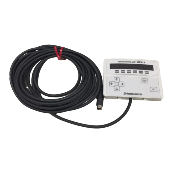
Accessories (sold separately) „ Data setter The data setter lets you set data and parameters for your AR Series DC power input built-in controller type with ease and also functions as a monitor. Model: OPX-2A „ Communication cable for the data setting software Be sure to purchase the communication cable for the data setting software when connecting a driver to the PC in which the MEXE02 has been installed. - Page 211 −211− 8 Appendix...
- Page 212 • Please contact your nearest Oriental Motor o ce for further information. Singapore Korea Technical Support Tel:(800)468-3982 Tel:1800-8420280 Tel:080-777-2042 8:30 to 5:00 , P.S.T. (M-F) A.M. P.M. www.orientalmotor.com.sg www.inaom.co.kr 7:30 to 5:00 , C.S.T. (M-F) A.M. P.M. www.orientalmotor.com Tel:1800-806161 Hong Kong Branch Tel:+55-11-3266-6018 www.orientalmotor.com.my...