Table of Contents
Advertisement
Quick Links
SIMEX
data logger
●
Loggy Soft v. 1.5.5 or higher
●
S-Toolkit v. 1.7.0 or higher
●
device type:
Read the user's manual carefully before starting to use the unit or software.
Producer reserves the right to implement changes without prior notice.
25.08.2008
®
USER MANUAL for
with 0/4 ÷ 20 mA inputs
SRD-99 - X100 - 1 - X - XX1
firmware version:
2.10 b972
or higher
V.2.06
Advertisement
Table of Contents

Related Manuals for Simex SRD-99

Summary of Contents for Simex SRD-99
- Page 1 ● Loggy Soft v. 1.5.5 or higher ● S-Toolkit v. 1.7.0 or higher ● SRD-99 - X100 - 1 - X - XX1 device type: 2.10 b972 firmware version: or higher Read the user's manual carefully before starting to use the unit or software.
-
Page 2: Table Of Contents
User manual for Data Logger and cooperating software CONTENTS I. USER MANUAL FOR “SRD-99” DATA LOGGER...........4 1. BASIC REQUIREMENTS AND USER SAFETY..................4 2. GENERAL CHARACTERISTICS........................5 3. TECHNICAL DATA............................6 4. DEVICE INSTALLATION..........................9 4.1. UNPACKING............................9 4.2. ASSEMBLY............................9 4.3. CONNECTION METHOD.........................12 4.4. MAINTENANCE..........................15 5. - Page 3 3.5.2.Configuring selected channels....................83 3.5.3.Configuring all channels......................83 3.6. UPDATING SOFTWARE OF SRD-99 DEVICE................84 Explanation of symbols used in the manual: - This symbol denotes especially important guidelines concerning the installation and operation of the device. Not complying with the guidelines denoted by this symbol may cause an accident, damage or equipment destruction.
-
Page 4: User Manual For "Srd-99" Data Logger
User manual for Data Logger and cooperating software I. USER MANUAL FOR “ SRD-99 ” DATA LOGGER 1. BASIC REQUIREMENTS AND USER SAFETY - The manufacturer is not responsible for any damages caused by inappropriate installation, not maintaining the proper technical condition and using the unit against its destination. -
Page 5: General Characteristics
Significant acceleration of data transfer is an additional advantage: data download can be 10 times faster than using RS-485 interface. WARNING! SRD-99 should work properly with any standard Flash Drives, but manufacturer can not guarantee proper cooperation with non-standard devices, or... -
Page 6: Technical Data
User manual for Data Logger and cooperating software • Wide range of power supply voltage and external sensor power supply The built-in pulse power supply allows power to be supplied to the unit with 85...230...260V AC/DC voltage or 16...24...35 AC, 19...24...50 DC voltage (depending on version). - Page 7 User manual for Data Logger and cooperating software Display LCD graphic display, 128 x 64 points, with backlight Data memory 2MB - version without USB Host 8MB - version with USB Host interface Protection level version without USB interface IP 65 (from front, after using waterproof cover) IP 40 (from front) IP 20 (housing and connection clips) version with USB interface IP 42 (from front, after using waterproof cover)
- Page 8 User manual for Data Logger and cooperating software Range of operating voltage Air gap [mm] Surface gap [mm] Up to 50V RMS or DC Up to 100V RMS or DC Up to 150V RMS or DC Up to 300V RMS or DC Tab.
-
Page 9: Device Installation
Attached with the unit please find: assembly brackets - 2 pieces, – warranty, – user’s manual for SRD-99 unit (device) – user’s manuals for cooperating software, – CD-ROM with the aforesaid manual in PDF format and installation files of cooperating –... - Page 10 User manual for Data Logger and cooperating software In order to assembly the unit, a 90,5 x 90,5 mm mounting hole (Fig. 4.1) must be prepared. The thickness of the material of which the panel is made must not exceed 5mm.
- Page 11 User manual for Data Logger and cooperating software GOOD back side of device connector WRONG back side of device connector Fig. 4.3. Connectors removing method 115 mm Fig. 4.4. Minimum distances when assembly of a number of units...
-
Page 12: Connection Method
User manual for Data Logger and cooperating software 4.3. CONNECTION METHOD Caution - Installation should be conducted by qualified personnel . During installation all available safety requirements should be considered. The fitter is responsible for executing the installation according to this manual, local safety and EMC regulations. - Page 13 User manual for Data Logger and cooperating software Use of screened signal cables is recommended. Signal cable screens should be connected to the earthing only at one of the ends of the screened cable. In the case of magnetically induced interference the use of twisted couples of signal cables (so-called “spirals”) is recommended.
- Page 14 User manual for Data Logger and cooperating software Depending on version: 85...230...260V AC/DC or 19...24...50V DC; 16...24...35V AC FUSE Fig. 4.7. Connection of power supply additional terminals (internally connected) 15 16 17 18 19 20 21 22 23 24 25 26 external 28 29 30 31 32 34 35 36 37 38...
-
Page 15: Maintenance
Fig. 4.10. Connection of digital input (depending on data recorder configuration) RS 485 12 13 RS232/485 interface Fig. 4.11. Connection of RS-485 transmission signals The SRD-99 device supports the following converters: USB / RS-485 converter (SRS-USB/4-Z45) – RS-232 / RS-485 converter ( SRS-2/4-Z45 ) – 4.4. MAINTENANCE The unit does not have any internal replaceable or adjustable components available to the user. -
Page 16: Front Panel Description
User manual for Data Logger and cooperating software 5. FRONT PANEL DESCRIPTION display programming pushbuttons Key designation and functions Symbols used in the manual: [ESC/MENU] and Functions: MENU MENU • go to main menu (press and hold by at least 2 sec.), •... -
Page 17: Principle Of Operation
User manual for Data Logger and cooperating software 6. PRINCIPLE OF OPERATION After turning the power supply on, the logo and basic unit data are showed on the display, then the unit goes to the measurement mode. 6.1. MEASUREMENT MODE In the measurement mode the unit executes the measurement of values of signals connected to current inputs, hereafter called measurement channels (the number of available channels depends on the unit version). - Page 18 User manual for Data Logger and cooperating software Values corresponding to the results of current measurement conducted for each channel can be recorded (stored in the non-volatile memory of the unit) for further analysis. The recording of measurement results for all channels is performed with the same frequency, defined by the user in the range between 1 record per second to 1 record per hour ("Rec.
-
Page 19: Modes Of Result Presentation
User manual for Data Logger and cooperating software Recording the measurement results in the non-volatile memory can be executed in two modes: "until full" or "cyclic" ("Write" parameter). The first mode enables the recording of such amounts of data as the unit's memory allows for, then the recording is stopped. In the second mode, once the memory is full, the results are recorded from the starting address in the memory, overwriting existing measurement results. -
Page 20: Single Channel" Mode
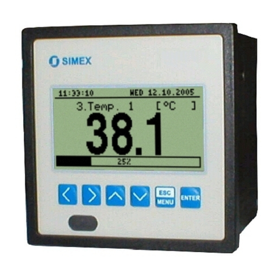
User manual for Data Logger and cooperating software - "Single channel" mode (Fig. 6.3) enables the last measurement for one of the measurement channels to be viewed in the numeric and graphic form (bar). Fig. 6.3. "Single channel" mode - "Measurements list" mode (Fig. 6.4) enables momentary values recorded during the set period of time or averaged values of the conducted measurements for one of the measurement channels to be viewed in numeric... - Page 21 User manual for Data Logger and cooperating software " Hi value ", " Lo value " parameters in the " Inputs settings " menu). channel name current date current time unit name channel number measure result bargraph in numerical mode percentage rate of measure result to nominal input range Fig.
-
Page 22: Measurements List" Mode
User manual for Data Logger and cooperating software Functions of keys in "Single channel" mode: • go to main menu (press and hold for approx. 2 seconds), MENU • change channel number, • change results presentation mode. 6.2.2. "Measurements list" mode The values displayed in this mode depend on the set type of recorded value (see description of parameters "Channel 1"..."Channel 8"... - Page 23 User manual for Data Logger and cooperating software channel name unit name channel number recorded overload recording date and time recorded measurements date and time of current measurement current measurement (displayed in negative mode) (not recorded yet) Fig. 6.11. Unit in “Measurements list” measurement results presentation mode. “List type”...
-
Page 24: Graph" Mode
User manual for Data Logger and cooperating software In the case of recording averaged values all indications in the " Measurements list " mode concerning values recorded in the unit's memory, constitute averaged values of measurement results. The current value indications concern only momentary measurement values. During the recording of averaged values of measurement results, the exceeding of the allowable measurement range is understood as exceeding this parameter by at least one from the current measurements incorporated into the averaging. - Page 25 User manual for Data Logger and cooperating software Numeric values (displayed over the graph) and vertical bar (displayed to the right of the graph) indicate the value corresponding to the result of the current measurement, irrespective of the set time scale of the graph. The graphical indicator (bar displayed to the right of the graph) always indicates the measurement result to the allowable measurement range ratio (see description of "...
- Page 26 User manual for Data Logger and cooperating software The vertical scale of the graph covers the values defined for the nominal range by " Hi value " and "Lo value" parameters including extensions ("Upper ext." and "Lower ext." parameters). warning message informing that input allowable range is exceeded arows inform that input allowable range is exceeded...
-
Page 27: Channels List" Mode
User manual for Data Logger and cooperating software If downloading the data (recorded measurement results) necessary for displaying the graph takes more than 1 second an appropriate message is displayed (Fig. 6.18). Pressing [ENTER] will stop the data downloading process and display a graph made on the basis of the data downloaded so far. -
Page 28: Device Programming
User manual for Data Logger and cooperating software indicating the direction of exceeding the range. If the measurement result for a given channel exceeds the allowable measurement range, instead of the current result in numeric form the display shows a "-Hi-" or "-Lo-" message (depending on the direction of exceeding, see description of "... - Page 29 User manual for Data Logger and cooperating software current menu name list position indicator presently selected menu item (submenu) Fig. 7.1. Main menu of the unit If the " Password " option in the " Access setup " menu was defined, then the user will have to provide the password (Fig.
-
Page 30: Parameters Edition
User manual for Data Logger and cooperating software After approximately 1 minute since the last activation of the keys, the unit returns from any level to one of the results presentation modes (only if no parameters are in editing mode). 7.1. -
Page 31: Text Parameters
User manual for Data Logger and cooperating software • Change of current value (i.e. flashing) of the digit (for numeric parameters) or switching status (for switching parameters, e.g. "Input type"). ENTER • Confirm the changes and end parameter editing. • Cancel changes. -
Page 32: Slider" - Type Parameters
User manual for Data Logger and cooperating software Functions of keys when editing selected character (at this time characters table is displayed below the edited parameter): • Selecting the character from the given line of characters table for the edited position of the text parameter. -
Page 33: Measurements List Options" Menu
User manual for Data Logger and cooperating software 7.2.1. "Measurements list options" menu This menu (Fig. 7.9) contains options configuring the method of displaying measurement results for the "Measurements list" mode: ”List type” - this option allows the establishing of which results of recorded measurements are to be presented. -
Page 34: Graph Options" Menu
User manual for Data Logger and cooperating software 7.2.2. ”Graph options” menu This menu contains options configuring the method of displaying measurement results for the "Graph" mode: ”Scale” - this option allows time points corresponding to particular points on the horizontal axis of the graph (time axis) to be defined. -
Page 35: Results Presentation Modes Menu Structure
User manual for Data Logger and cooperating software 7.3. RESULTS PRESENTATION MODES MENU STRUCTURE Main menu Power on Initialization MENU Channel selection Mode: ”Single channel” ENTER MENU Parameter MENU Mode: ”Measurements list” Measurements list options List type edition ENTER MENU MENU Channel selection Date... -
Page 36: Display Options" Menu
User manual for Data Logger and cooperating software established on the basis of the currently set recording period and the number of recorded channels. In the case of controlling the recording process using the digital input, the value shown relates to the time, during which the voltage level on the digital input allows the recording of measurements. -
Page 37: Logging Setup" Menu
User manual for Data Logger and cooperating software Fig. 7.14. ”Display options” menu 7.4.3. ”Logging setup” menu This menu contains options defining the recording method and recorded channels: ”Write” - this option defines the behaviour of the unit after writing all available memory with the recorded measurement results. - Page 38 User manual for Data Logger and cooperating software Fig. 7.16. Warning in “cyclic” recording mode ”Triggering” - method of recording measurement results. The following options are available: ”always” - measurements are recorded in time intervals defined by the “Recording period” parameter, ”high level”...
-
Page 39: Input Settings" Menu
User manual for Data Logger and cooperating software ”average v.” - averaged values will be recorded for the selected measurement channel (see section MEASUREMENT MODE, point 6.1.1). If the “Input type” in the “Inputs settings” menu shall be set as “disabled” for a given channel, then this channel will not be available on the list of recording channels in the “Logging setup”... - Page 40 User manual for Data Logger and cooperating software Fig. 7.19. ”Inputs settings” (part 1) ”Input type” - type of input/sensor. The following options are available: ”inactive” - input is not active ”0-20 mA”,”4-20 mA” - current inputs, displayed value is defined by “Hi value”, “...
-
Page 41: Date & Time Settings" Menu
User manual for Data Logger and cooperating software ”Filter” - this option enables the level of the filtration of indications to be changed. Permissible values: from 0 (no filtration) to 5 (filtration with maximum time constant of approx. 2 seconds). - parameter defining the allowable range of input currents (Fig. -
Page 42: Rs485 Port Settings" Menu
User manual for Data Logger and cooperating software Fig. 7.22. ”Date & time settings” menu 7.4.6. ”RS485 port settings” menu This menu contains options to configure the RS485 interface: ”Address” - this parameter specifies the unit’s address, according to the Modbus protocol (in the range of 0 to 99). -
Page 43: Access Setup" Menu
User manual for Data Logger and cooperating software “38400” “57600” “115200” ”Baud rate” parameter “+10 ch.” “+20 ch.” “+50 ch.” ”Resp. delay” parameter Tab. 7.1. Settings of ”Resp. delay” parameter ”Conf. change” - this option allows the method of accessing unit’s configuration registers through the RS485 interface to be defined. -
Page 44: Usb Options" Menu
User manual for Data Logger and cooperating software Fig. 7.24. “Access setup” menu 7.4.8. ”USB options” menu This menu contains options which allows copying of device configurations between PC and data logger unit, and automatic data transfer using USB type FlashDrive (PenDrive): ”Write config. -
Page 45: Language" Parameter
User manual for Data Logger and cooperating software memory of the device. Due to the possibility of occurrence of: write error, FlashDrive or USB malfunction, and other incidental problems, autostorage function should be controlled by user from time to time. Lack of control can cause overwriting of data in internal memory or stopping of data recording due to impossibility of data storage on FlashDrive. -
Page 46: Main Menu Structure
User manual for Data Logger and cooperating software 7.5. MAIN MENU STRUCTURE Result presentation mode Press and hold at least 2 seconds MENU MENU 4-digit user password entering (if it is different from „0000”) 0 _ _ _ ENTER ENTER Parameters MENU Device information... -
Page 47: Downloading Data From Data Logger
PC - SRD-99 interconnection. To get data from the SRD-99 device plug a FlashDrive to USB Host port, located on the front panel of the device. The following message will appear after a few seconds: User can confirm ([ENTER] key) to start data downloading , or cancel the download ( [ESC/MENU] key). -
Page 48: The Modbus Protocol Handling
User manual for Data Logger and cooperating software 9. THE MODBUS PRO TOCOL HANDLING Transmission parameters: 1 start bit, 8 data bits, 1 stop bit, no parity control Baud rate: selectable from: 1200 to 115200 bits/second Transmission protocol: MODBUS RTU compatible The device parameters and measurement result are available via RS-485 interface, as HOLDING-type registers of Modbus RTU protocol. - Page 49 User manual for Data Logger and cooperating software Register Write Range Register description Control registry for time-related settings: 0 - startup of continued update of registries 18h ÷ 1Eh by internal clock (current time and date), 80h - stopping update of registries 18h ÷ 1Eh by internal clock (automatically after writing one of 18h ÷...
- Page 50 User manual for Data Logger and cooperating software Register Write Range Register description Approximated time remaining until memory is filled with recorded measurement results – Higher (2 ) byte (parameter in seconds). Approximated time remaining until memory is filled with recorded measurement results –...
-
Page 51: Transmission Errors Handling
User manual for Data Logger and cooperating software Register Write Range Register description Parameters in “Inputs settings” submenu for channel 6; registry Register from 90h to 9Dh description like for channel 1 (see registers 40h do 4Dh). Parameters in “Inputs settings” submenu for channel 7; registry Register from A0h to ADh description like for channel 1 (see registers 40h do 4Dh). - Page 52 User manual for Data Logger and cooperating software ADDR FUNC REG H,L COUNT H,L CRC L,H The answer: ADDR FUNC BYTE C DATA H,L CRC L,H DATA H,L - identification code (007Ah) 2. Change of the device address from 1 to 2 (write to reg. 20h) ADDR FUNC REG H,L...
- Page 53 User manual for Data Logger and cooperating software ADDR FUNC REG H,L COUNT H,L CRC L,H COUNT L - the count of being read registers (max. 32) The answer: ADDR FUNC BYTE C DATA H1,L1 DATA H2,L2 DATA H3,L3 CRC L,H DATA H1, L1 - 01h registry (10 –...
- Page 54 User manual for Data Logger and cooperating software 6. Change of baud rate of all devices connected to the net (BROADCAST message). ADDR FUNC REG H,L COUNT H,L CRC L,H DATA H DATA L - 4, new baud rate 19200 baud Device do not reply to BROADCAST-type messages.
-
Page 55: User's Settings List
User manual for Data Logger and cooperating software 10. USER'S SETTINGS LIST Description Parameter Description Value page Parameters in the "Measurements list options” menu List type Type of measurement results list Date, Time Position of time line on historical list Parameters in the "Graph options”... - Page 56 User manual for Data Logger and cooperating software Description Parameter Description Value page Unit Unit for measured value Input type Type of input/sensor Value displayed for maximum value of input Hi value current Value displayed for minimum value of input Lo value current Dec.
- Page 57 User manual for Data Logger and cooperating software Description Parameter Description Value page Unit Unit for measured value Input type Type of input/sensor Value displayed for maximum value of input Hi value current Value displayed for minimum value of input Lo value current Dec.
- Page 58 User manual for Data Logger and cooperating software Description Parameter Description Value page Unit Unit for measured value Input type Type of input/sensor Value displayed for maximum value of input Hi value current Value displayed for minimum value of input Lo value current Dec.
-
Page 59: User Manual For "Loggy Soft
The Loggy Soft program enables the visualization, archiving and printing of measurements (e.g. temperature, humidity, pressure) stored in SRD-99-type device memory. Work with SRD-99 -type devices takes place through an RS485 serial interface, or via the USB FlashDrive (PenDrive) device (optional interface of SRD-99). Connecting a network of units to a serial port (RS 232) or USB port of a PC is possible using a proper converter (RS 485 to RS 232 or RS 485 to USB). - Page 60 After defining the communications port and baud rate, go to device detection screen (Fig. 2.2) by clicking on the [Next>>] button. Prior to scanning the network for devices, set the addresses identifying the selected SRD-99 devices in the network (a different address for each device – see page 42). In order to detect units connected to the network (after assigning addresses to the devices) press the [Scan network] button.
- Page 61 The list shown on the figure (Fig. 2.2) contains one detected device. Order of devices on the list corresponds to the order of addresses assigned by the user to individual SRD-99 devices. Once all devices are detected press [Break scanning] button.
-
Page 62: Using The Program
User manual for Data Logger and cooperating software 3. USING THE PROGRAM Upon application startup the Current measure menu is displayed (Fig. 3.1). Fig. 3.1Program window upon startup The selection from the currently active menu is made using the flat buttons in the upper part of the program window (Fig. -
Page 63: Current Measure" Menu
3.1. „ CURRENT MEASURE ” MENU Current measures menu allows to view current measurements results in table format. This table contains measures of channels of all installed SRD-99 units. Only the measurements from devices installed using the RS485 interface will be available. To enable continuous reading of data from the devices check Enable current measurement mode . -
Page 64: Table" Tab
- this box enables creating tables in two modes: - for a group - collective table for a maximum of 12 measurement channels (observed channels can belong to different SRD-99 devices), - for a single channel. Creating groups is described in the Group operations section (page 73). - Page 65 User manual for Data Logger and cooperating software Selecting table type (for a group or single channel) In order to select table type: click appropriate tab Groups or Channels (Fig. 3.3), • • check specific group or measurement channel. This will display measurement results for the selected group or single channel (displaying results takes place automatically after each change of group or measurement channel).
-
Page 66: Graph" Tab
Fig. 3.6. Reports - Graph tab Graph tab (Fig. 3.6) is used for viewing and printing of measurement results recorded by an SRD-99 device (e.g. temperature, humidity) in the form of a graph. Measurements from a maximum of five recorded measurement channels can be viewed. - Page 67 - this box enables creating graphs in two modes: - for a group - collective graph for a maximum of 12 measurement channels (observed channels can belong to different SRD-99 devices); - for a single channel. Creating groups is described in the Group operations section (3.3.2, page 73).
- Page 68 User manual for Data Logger and cooperating software Fig. 3.7. Enlarging graph moving the graph • - the graph can be moved to the left/right (earlier/later time period, correspondingly). In order to do this, right-click on the graph and drag the pointer in desired direction (Fig. 3.8). Fig.
- Page 69 User manual for Data Logger and cooperating software • measurement points tracking - if Show cursor field is checked then special graphical cursor is displayed on the graph. This cursor allows to easy tracking of measured data. Colour of the cursor is same as selected channel colour.
- Page 70 Fig. 3.10. Interruption in the graph (e.g. sensor fault) If measurements can not be executed for some time (e.g. power supply fault or the SRD-99 device is switched off) then the program will show this situation on the graph in the form of two vertical lines (Fig.
-
Page 71: Configuration" Menu
PC USB port and confirm the data download. The database of recorded measurements will be updated. 3.3. „ CONFIGURATION ” MENU The Configuration menu is used to: change the settings of channels of SRD-99 devices working in the system and getting data • from these devices (Devices tab); •... - Page 72 - shows the tree contains a list of all currently installed SRD-99 devices together with their addresses. The first level of the tree shows individual SRD-99 devices. After clicking the “+” sign next to the SRD-99 device name with mouse pointer,...
-
Page 73: Groups" Tab - Group Operations
A group enables creating a collective current graph/report for a number of measurement channels belonging to the same or to different SRD-99 devices, which the user wishes to view on one graph/report. A group consists of a maximum of 12 measurement channels. - Page 74 User manual for Data Logger and cooperating software Removing a group In order to remove a group: • check the desired group on the Groups list, click on the [Remove group] button. • Changing group name In order to change a group’s name: check the desired group on the Groups list, •...
-
Page 75: Settings" Tab
User manual for Data Logger and cooperating software 3.3.3. „ Settings ” ta b Fig. 3.15. Configuration - Settings tab Settings tab (Fig. 3.15) allows to change settings related to serial port and method of data downloading from the USB FlashDisk. The settings list contains following fields: Port field •... -
Page 76: List Of Errors And Fault Diagnostics
User manual for Data Logger and cooperating software 3.4. LIST OF ERRORS AND FAULT DIAGNOSTICS Symptom Cause Action All points are a red colour converter fault or one of • check converter power supply and a question mark (?) is converter's connections •... -
Page 77: User Manual For "S-Toolkit
1. GENERAL CHARACTERISTICS The S-Toolkit software enables configuration reading and writing operations, updating the device firmware and obtaining basic information on SRD-99 -type devices through RS485 serial interface. This application enables to quickly and easily define device parameters in one of three possible configuration models. -
Page 78: Using Program
User manual for Data Logger and cooperating software 3. USING PROGRAM Read current settings from device, from file or import settings from flash disk Write configuration set to device, to file or export settings to flash disk Fig. 3.1. Program main window There are four tabs in the central part of program window: •... -
Page 79: Inputs Settings" Tab
User manual for Data Logger and cooperating software [Export] • - saves the settings shown in the Inputs settings tab and writes the configuration set to the FlashDrive; [Close] • - exits the program. Status information concerning currently performed operation is shown in the bottom of the window. -
Page 80: Logging Setup" Tab
In the central part of the tab (in a separated panel) there are fields for configuring device parameters. The parameters can be configured in three modes. Detailed description of individual parameters can be found in the user manual for device SRD-99 . •... -
Page 81: Interface Options" Tab
In order for communication between the program and the device to be possible, the address and baud rate set in the program must be same as the ones set in the SRD-99 device. Display options •... -
Page 82: Device Information" Tab
User manual for Data Logger and cooperating software If the SRD-99 device clock shows later time than computer's system clock, then the synchronization (in this case reversing the SRD-99 clock) will cause all data recorded by device after the time set during synchronization to be deleted. -
Page 83: Configuration Modes
SRD-99 device. Therefore perform one of the aforesaid operations prior to configuring the next group of selected channels. Due to the time of writing the configuration to SRD-99 device it is recommended to write the set configuration to file. 3.5.3. Configuring all channels After switching to all-channels configuration mode, the values for most recently configured channel remain in the configuration fields. -
Page 84: Updating Software Of Srd-99 Device
In exceptional cases (update interrupted or unit does not operate after update) contact the manufacturer. The newest version of SRD-99 device firmware is available at producer homepage. The USB driver update section in the Device information tab enables USB interface driver update. - Page 85 User manual for Data Logger and cooperating software...
- Page 86 User manual for Data Logger and cooperating software...
- Page 87 User manual for Data Logger and cooperating software...
- Page 88 ® SIMEX SIMEX Sp. z o.o. , ul. Wielopole 7 PL - 80-556 Gdańsk, Poland tel. : (+48 58) 762-07-77, fax: (+48 58) 762-07-70 http://www.simex.com.pl, e-mail: info@simex.com.pl...
Need help?
Do you have a question about the SRD-99 and is the answer not in the manual?
Questions and answers