Mase IS3501 Installation Manual
Hide thumbs
Also See for IS3501:
- Use and maintenance manual (9 pages) ,
- Usage and maintenance manual (22 pages)
Table of Contents
Advertisement
Quick Links
Advertisement
Table of Contents

Related Manuals for Mase IS3501


Summary of Contents for Mase IS3501
- Page 1 IS3501 IS5501 INSTALLATION MANUAL #11501...
-
Page 2: Table Of Contents
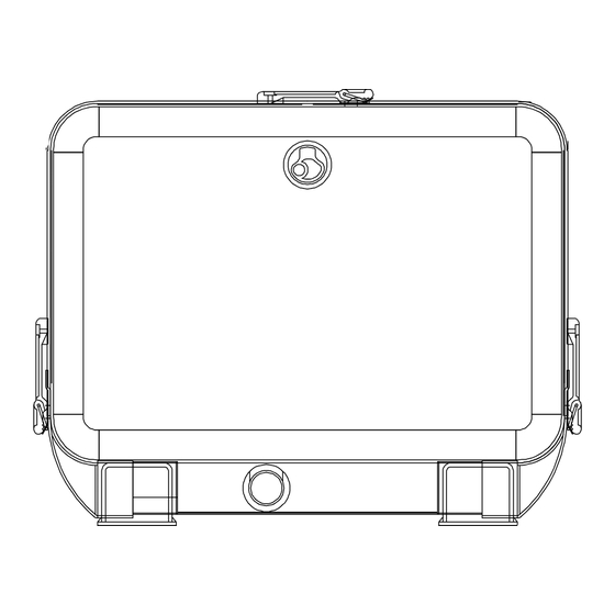
IS 3501 THE WARRANTY MAY BE VOIDED IF THE SPECIFICATIONS CONTAINED IN THE FOLLOWING INSTALLATION MANUAL ARE NOT FOLLOWED INSTALLATION 1.1 Installation space requirements ......3 1.2 Fastening the unit ..........3 1.3 Ventilation ............3 COOLING WATER CIRCUIT 2.1. Raw water feed system ........3 2.2 Typical installation with electric generator above the water-line .......... -
Page 3: Installation
2.0. COOLING WATER CIRCUIT The IS3501 and IS5501 motor is cooled by an open- Fig. 3 circuit system in which sea water circulates. The capacity of the sea water circuit is 238 gal./h (IS 3501) and 317 gal./h (IS 5501). - Page 4 THE DIRECT INFEED SYSTEM SUPPLIED BY MASE HAS BEEN MODIFIED TO PREVENT SOLID OBJECTS FROM ENTERING AND BLOCKING THE SYSTEM. IF A NON-MASE COMPONENT IS USED, MORE CARE AND MORE FREQUENT CLEANING IS NECESSARY. The baffle system might cause the following problems:...
-
Page 5: Typical Installation With Electric Generator Above The Water-Line
2.2. Typical installation with electric generator above the water-line (fig. 4) Raw water intake Intake valve Valve to drain system Water filter Electric generator Muffler Silencer Exhaust through-hull Water line Fig. 4 IMPORTANT A - Hose - internal diameter 45 mm (1.77") B - Hose - internal diameter 15 mm (.59") C - Clamps CAUTION... - Page 6 Fig. 6 Fig. 7 Anti-siphon valve Exhaust manifold Water pump Fig. 8 ANTI-SIPHON VALVE Fig. 9...
-
Page 7: Components
2.4. Components 1 - Raw water intake 1/2" IMPORTANT If the unit is installed more than 40" above the water- line, a check valve should be fitted after the sea intake (fig. 6, ref. 1) to prevent the raw water circuit emptying when the motor is off. -
Page 8: Drainage System
2.5. Drainage system IS3501 The exhaust system of the generator must be separate from that of the main engine(s) IMPORTANT The length of the hose from the highest point of the drain duct to the muffler should not exceed 80". This is to prevent the water left in the drainage hose returning to the motor after filling the water lock muffler, when the unit is turned off. -
Page 9: Battery Connection
4.0. ELECTRICAL CONNECTIONS 4.1. Battery connection 5-1/32" To start the genset, an independent 12V battery, 18 - 30 capacity Ah min is needed. 4-3/4" It should be connected to the generator as shown in fig. 11 with cables up to 16'. For longer distances, follow the sequence of operations described below: - First connect the positive pole (+) of the battery to the terminal marked with the symbol (+) on the generator,... -
Page 10: Connection
The control panel is necessary for operating the unit - Ensure that the sum of the loads to be supplied does and must be installed; use of a non-Mase control not exceed the nominal power of the electric generator. panel could present compatibity problems. - Page 11 IS 3501 Fig.18 2900 2900 24.2 12.1 LOAD IS5501 LOAD 4800 4800 Fig.19 MAIN IS 3501 IS5501 120/240 120/240 2900 4800 12.1 LOAD Fig.20...
Need help?
Do you have a question about the IS3501 and is the answer not in the manual?
Questions and answers