
Related Manuals for Mase IS 2.6


Summary of Contents for Mase IS 2.6
- Page 1 USE, MAINTENANCE AND INSTALLATION MANUAL IS 2.6 Rev.0 A.A. 04/06/2008 cod.42889 Modello / Modelo N° matricola / Matrìcula Codice / Còdigo...
- Page 2 IS 2.6...
- Page 3 Thank you for having chosen a product MASE. As a leading generator manufacturer, Mase Generators offers a wide range of generators with an output from 1 KVA portable generators to 1600 KVA units for special applications.
-
Page 4: Table Of Contents
IS 2.6 CONTENTS DEFINITIONS USED ..........5 PRELIMINARY PRESCRIPTIONS ......7 GENERAL INFORMATIONS ......8 MAINTENANCE ..........32 1.1 Conform use ............. 8 6.1 Preamble ............32 1.2 Residual risks ............ 8 6.2 Routine engine maintenance ......32 1.3 Safety symbols ..........9 6.3 Engine oil check .......... -
Page 5: Gb Definitions Used
A person able to evaluate the job assigned to him and recognise the possible dangers on the basis of training at the MASE training centres, with professional experience and knowledge of the equipment in question and of the possible dangers deriving in the event of negligent behaviour. - Page 6 IS 2.6 - Connection in bad state The live parts are not fully covered with insulation removable by destruction only, the connections are not secure because of unstable tightening of the parts and a development of oxide between the parts.
-
Page 7: Preliminary Prescriptions
Ongoing improvement and development of the product may have led to modifications to the generator which are not included in this publication. Whenever a problem concerning the generator or this publication arises, consult with Mase Generators SPA for the latest information available. -
Page 8: General Informations
IS 2.6 1 GENERAL INFORMATIONS 1.1 C ONFORM USE The generator is suitable for independent production of electrical energy within the voltage and wattage limits declared by the manufacturer. Any other use outside the already stated field of use is prohibited: the generator is intended for marine use. -
Page 9: Safety Symbols
IS 2.6 SAFETY INSTRUCTIONS The electromechanics equipments, included the generating sets, switch, command electric equipments and accessories, can cause damages to people and,if they are installed, used or mainteined with not qualified operations, they can put in serious danger the life of people. To avoid accidents is necessary to know the potential risks and operate with caution.Read and follow all the precautions and the instructions for the safety. -
Page 10: Symbols On The Generator Group
IS 2.6 1.4 S YMBOLS ON THE GENERATOR GROUP Cod. 42656 Cod. 42653 Cod.42585 Cod. 42655 Cod. 41810 Cod. 41781 Cod. 42657 - 10... -
Page 11: Safety Label Informations
IS 2.6 1.5 S AFETY LABEL INFORMATIONS • These labels warn the user of any danger which may cause serious injury. Carefully read the meaning and the precautions described in this manual. • If the label detaches or becomes illegible, replace it with a new one which can be requested from an authorised mase dealer. - Page 12 IS 2.6 Danger Symbols Description PREVENTING FIRE Can cause severe injury or death. • Start • Start the engine only from a starter switch without any load or in neutral posi- tion of the clutch of machine unit. The machine unit suddenly starts to move or generates power to cause serious personal injury.
- Page 13 IS 2.6 Danger Symbols Description EXHAUST SYSTEM Carbon monoxide. Group generator use. Carbon monoxide can cause severe nausea, fainting, or death. Carbon monoxide is an odorless, colorless,tasteless, non irritating gas,able to, if inhaled only also for brief time to provoke the death.
- Page 14 IS 2.6 Danger Symbols Description BATTERY Do not touch the electrolitic battery acid Sufficient ventilation of the battery area. • Keep the area around the battery well ventilated, paying attention to keep sparks, open flame and any other form of ignition away. During engine running or charging battery, hydrogen gas is produced from the battery and can be easily ignited.
-
Page 15: Reference Documents
IS 2.6 1.6 R 1.8 M EFERENCE DOCUMENTS ARKING The instructions for use provided with each generator The generator identification plate carries all the are made up of a collection of documents of which this identification data conforming to ISO 8528 and in manual represents the General Part. -
Page 16: General Characteristics
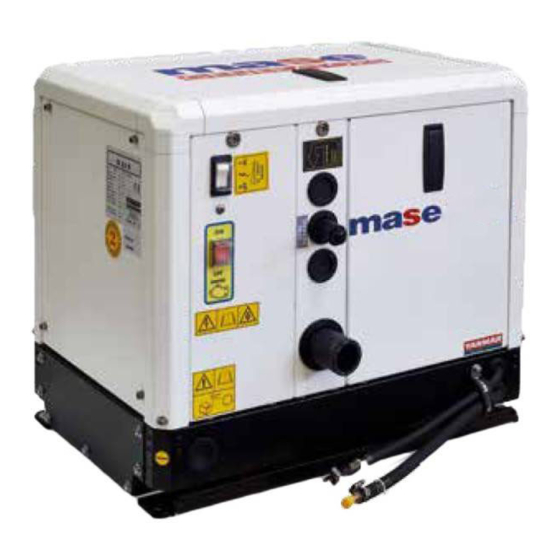
IS 2.6 2 GENERAL CHARACTERISTICS The generators have been designed for use in the marine field, using highly reliable 3000 rpm air/water- cooled diesel engines. Particular attention has been paid to the degree of protection against external agents, engine protection and protection of the electrical parts... -
Page 17: Command And Control Panel
IS 2.6 2.2 C OMMAND AND CONTROL PANEL STANDARD VERSION Each generator is fitted with an instrument panel for commands and controls with the following components: 1) HOURCOUNTER 2) OFF BUTTON 3) START BUTTON 4) ON BUTTON 5) ON PANEL LED (GREEN) -
Page 18: Table Of Technical Characteristics
IS 2.6 2.3 T ECHNICAL CHARACTERISTICS TABLE IS 2.6 MODEL GENERAL FEATURES MAX POWER (LTP) CONTINUOUS POWER (PRP) POWER FACTOR (Cos Φ) RATED VOLTAGE RATED FREQUENCY GRADE OF PROTECTION IP 23 MAX TEMP. OF USE ° C - ° F 40 - 104 MIN TEMP. -
Page 19: Installation
IS 2.6 3 INSTALLATION The generator may only be installed by qualified technicians. Malfunctioning due to improper installation may cause injury or death. GENERATOR HOUSING CHARACTERISTICS - The generator must be installed in a sufficiently ventilated room able to assure the small amount of air required for engine combustion. -
Page 20: Cooling Water Circuit
IS 2.6 3.5 C OOLING WATER CIRCUIT The generator engine is cooled by an open-circuit system in which seawater circulates. At the time of installation, a seawater feed circuit must be arranged for cooling, and an exhaust system for the combustion gas and water mixture. -
Page 21: 2Components
IS 2.6 3.5.2 C OMPONENTS If the generator is installed at a height over 1m (3,3ft) above the waterline, a check valve (ref.2) must be fitted after the seawater intake to prevent the water circuit from emptying out when the engine is off. If the circuit is empty, the water pump impeller may be damaged during starting. -
Page 22: 3Typical Installation With The Generator Below The Waterline
IS 2.6 3.5.3 T YPICAL NSTALLATION ENERATOR ELOW ATERLINE Water/gas separator IMPORTANT A - Internal diameter pipe 45 mm. B - Neoprene rubber pipe, internal diameter 16 mm. C - Internal diameter pipe 40 mm. D - Internal diameter pipe 25 mm. -
Page 23: 5Exhaust System
IS 2.6 3.5.5 E XHAUST SYSTEM The generator combustion gas/water exhaust system Muffler must be independent of that of the main engines. See installation diagrams. The pipe length from the highest point of the exhaust pipe to the exhaust must not exceed 2m (6.6... -
Page 24: Fuel Circuit
IS 2.6 3.6 F IRCUIT The generator is diesel-powered by means of the unions marked "DIESEL FUEL INLET" (rif.1) e "DIESEL FUEL OUTLET" (rif.2); the latter serves to return excess fuel. The fuel pipes must be in hydrocarbon-resistant rubber with an inside diameter of 8mm (0.31in). -
Page 25: Electrical Connections
IS 2.6 3.7.1 B ATTERY CONNECTION Use a 12V stand-alone battery to start the generator. Connect it to the generator terminals using cables of 25mm cross-section for a distance up to 5m (16.4ft) cables of 35mm cross-section for longer distances,... -
Page 26: C. Connection
IS 2.6 The control panel must necessarily be installed as it is essential for generator operation. Do not use devices different from the control provided with the generator, since they may be incompatible with the generator. Make the connection with the battery detached. -
Page 27: 4Generator-Network Switching
IS 2.6 - Make sure that the sum of the generator loads doesn't overcome the nominal power of the generator group. - Despite the group is provided with a thermal switch (rif.1), it's recommend to interpose magnetothermal protections or similar between generator and electric users, according to the following table. -
Page 28: Using The Generator
IS 2.6 4 USING THE GENERATOR 4.1 P RELIMINARY HECKS Before beginning with any starting procedures, it is extremely important to “familiarise” yourself with the generator and its controls. Furthermore, visually inspect the generator and the installation. Any source of real or potential risk must be eliminated before proceeding. -
Page 29: Starting The Generator
IS 2.6 4.3 S TARTING THE GENERATOR Before starting the generator check that all the doors is closed. Before starting the generator ensure that all the preliminary checks have been carried out. Starting Proceed with starting by pressing the ON button (ref.4),You will note that all the LEDs come on while a... -
Page 30: Safety Switches And Warning Signals
IS 2.6 5 SAFETY SWITCHES AND WARNING SIGNALS The generators are equipped with a set of safety switches which protect it against improper use and problems which may jeopardise its integrity. 5.1 P ROTECTION GAINST HORT CIRCUITS VERLOAD The generator is protected against short-circuits and electrical overload. -
Page 31: Control Panel - Alarm Codes
IS 2.6 5.3 C ONTROL ANEL LARM ODES When the generator stops because one of the safety switches has tripped, the indication of the hours of operation disappears from the control panel display (ref.1) and a code appears to indicate the cause of the generator stop. -
Page 32: Maintenance
IS 2.6 6 MAINTENANCE 6.3 E NGINE HECK 6.1 P REAMBLE - Check the oil level by means of the cap/dipstick (ref.1). It is recommended to strictly follow the instructions in the manual provided by the engine manufacturer, The oil level must always be between the MAX and MIN notches engraved on the dipstick. -
Page 33: Engine Oil Change
IS 2.6 6.4 E NGINE OIL CHANGE Use diesel engine oil Top up the engine oil through the hole (ref.1). To change the oil in the engine oil sump, take out the dipstick (ref.1). Suct exhaust oil with a manual pump (ref.2). -
Page 34: Replacing / Cleaning The Fuel Pump Filter
IS 2.6 6.6 R EPLACING LEANING ILTER This operation is carried out following the steps below: - Remove the pipe (ref.1) - Slide out the filter (ref.2) - Clean or replace it For reassembly repeat the operations in reverse order. -
Page 35: Draining The Cooling System
IS 2.6 6.10 DRAINING THE COOLING SYSTEM In order to carry out maintenance on the water/air Genset exchanger or the cooling system, the seawater intake circuit must be drained. Carry out this operation as follows: - Close the seawater intake cock (ref.1). -
Page 36: Seawater Pump Maintenance
IS 2.6 6.12 S EAWATER PUMP MAINTENANCE At least once a year check the integrity of the rubber seawater pump impeller. Before opening the seawater pump to inspect the impeller, drain the seawater from the cooling system as described in paragraph 6.10. -
Page 37: Alternator Maintenance
IS 2.6 6.14 ALTERNATOR MAINTENANCE The alternator used on this model generator is type synchronous, self-excited. This type of brushless alternator without manifold does not require any particular maintenance. Periodic inspections and maintenance are limited to eliminating any traces of moisture and oxidation which may damage it. -
Page 38: List Of Recommended Spare Parts
Fuel filter Zinc anode Fuses A kit with recommended spare parts is available and may be ordered from the Mase Service Network or Technical Service. 6.17 P ERIODS OF INACTIVITY Start up the generator at least once a month. If the... -
Page 39: Period Checks And Maintenance
IS 2.6 6.18 P ERIOD CHECKS AND MAINTENANCE Every Every 50 Every 200 Every 400 Every 500 Before 1000 Perform service at intervals indicated hrs.or 1 hrs.or 3 hrs.or 6 hrs.or starting hrs.or Month Month Month Yearly Yearly Fuel system Check the fuel level and refill ○... -
Page 40: Anomalies, Causes And Remedies
IS 2.6 6.19 A NOMALIES CAUSES AND REMEDIES The starter motor turns but the main engine does not start - Check that there is fuel in the tank. (Fill up) - Check if the stop electromagnet is in the firing position. (Consult Service Centre) - Check that the emergency button is in ON position. -
Page 41: Handling And Packaging
7 TRANSPORT, STORAGE, LIFTING AND, HANDLING AND PACKAGING 7.1 T RANSPORT AND STORAGE Packaging: Supplied directly by Mase Generators. The total weight of the packed generator is given in Paragraph 2.3 “Table of technical characteristics”. Transport: During transport the generator (with or... -
Page 42: Guarantee And Responsability
8.2 L IMITS OF RESPONSIBILITY MASE GENERATORS S.p.A is responsible for anything regarding the safety, reliability and performance of the Generator on the condition that: • The generator is used by persons trained through the use and maintenance manual. -
Page 43: Wiring Diagrams
F1 P2 Cod.48132 ALTERNATOR OIL PRESSURE SWITCH EARTH CONNECTION RELAY CARD BATTERY CHARGE REGULATOR SCREW BATTERY ENGINE THERMOSTAT ALTERNATOR THERMOSTAT CAPACITOR ENGINE THERMOSTAT POWER TERMINAL BOARD FUSE FUEL CUT-OUT SOLENOID FUEL PUMP FUSE CONNECTOR GENERAL SWITCH ENGINE PROTECTION MODULE CONNECTOR STARTER MOTOR CONNECTOR... - Page 44 Mase Generators S.p.a. • Via Tortona, 345 • 47023 Cesena (FC) ITALY • Tel. (+39) 0547.35.43.11 Fax (+39) 0547.31.75.55 • www.masegenerators.com • e-mail mase@masegenerators.com...
Need help?
Do you have a question about the IS 2.6 and is the answer not in the manual?
Questions and answers