Table of Contents
Advertisement
Quick Links
Download this manual
See also:
Owner's Manual
Advertisement
Table of Contents

Subscribe to Our Youtube Channel
Related Manuals for Daewoo DS-2000N


Summary of Contents for Daewoo DS-2000N
- Page 1 MODEL SERVICE MANUAL DS-2000N CAUTION : Before servicing this chassis, read the "PRODUCT SAFETY SERVICE FOR VIDEO PRODUCTS" section on page 2 of this manual. DVD and CD PLAYER...
- Page 2 SEPECIFICATION DVD VIDEO PLAYER Signal system NTSC/AUTO/PAL Laser wavelength 650nm Frequency response 20Hz 20kHz Signal/Noise ratio 85dB Audio distortion+noise -80dB(1kHz) Channel Separation 90dB(1kHz) Dynamic range 85dB(1kHz) OUTPUTS Video outputs 1.0V(p-p), 75ohm, negative sync. S-video outputs (Y)1.0V(p-p), (C)0.286V(p-p) 75ohm, negative sync. Audio outputs (digital audio) 0.5V(p-p), 75ohm Audio outputs (analog audio)
- Page 3 PRODUCT SAFETY SERVICING GUIDELINES FOR VIDEO PRODUCTS CAUTION: DO NOT ATTEMPTTOMODIFYTHISPRODUCTINANYWAYAND SUBJECT:X-RADIATION N E V E R P E R F O R M C U S T O M I Z E D I N S T A L L A T I O N S W I T H O U T 1.BESUREPROCEDURESANDINSTRUCTIONSTOALLSERVICEPERSONNEL MANUFACTURER'SAPPROVAL.
-
Page 4: Servicing Precautions
SERVICING PRECAUTIONS CAUTION : Before servicing the DVD covered by this ElectrostaticallySensitive(ES)Devices service data and its supplements and ADDENDUMS, read Some semiconductor (solidstate)devicescan bedamaged and follow the SAFETY PRECAUTIONS NOTE : if easily by static electricity. Such components commonly are unforeseen circumstances create conflict between the called ElectrostaticallySensitive(ES) Devices.Examplesof following servicing precautions and any of the safety... -
Page 5: Table Of Contents
TABLE OF CONTENTS 1. CONTROLS AND FUNCTIONS 2. ELECTRICAL ADJUSTMENTS 3. ELECTRICAL TROUBLE SHOOTING GUIDE 4. WAVEEFORMS ON VIDEO CIRCUIT 5. ACTION OF PORT 6.VOLTAGE CHART 7. CIRCUIT DIAGRAM 8. COMPONENTS LOCATION GUIDE ON PCB BOTTOM VIEW 9. DISASSEMBLY 10. ELECTRICAL PARTS LIST... -
Page 6: Controls And Functions
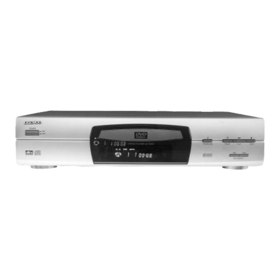
1. CONTROLS AND FUNCTIONS FRONT PANEL POWER PAUSE DISC TRAY DISPLAY OPEN/CLOSE REMOTE SENSOR PLAY STOP SKIP/SEARCH... -
Page 7: Rear Panel
DISPLAY program indicator chapter/track repeat play Dolby digital angle title indicator indicator pause indicator CD indicator indicator track calendar indicator indicator remain indicator play indicator lock indicator second disc recording minute indicator format indicator DVD indicator title/chapter/track hour resume indicator indicator indicator Press DIMMER , the brightness of the display is reduced by half;... -
Page 8: Names And Layout Of Remote Controls
NAMES AND LAYOUT OF REMOTE CONTROLS DIMMER NUMBER BUTTONS FF/FR SET UP TITLE PLAY/ENTER PREV/NEXT(SKIP/SEARCH) STOP DIRECTIONS SYSTEM LANGUAGE MUTE VOLUME(-/+) SUBTITLE AUDIO MODE A-B REPEAT REPEAT MENU PAUSE/STEP SLOW PLAY ZOOM REMAIN RESUME TIME SEARCH DIGEST PLAY MODE ANGLE OPEN/COLSE REMOTE TRANSMITTER... -
Page 9: Electrical Adjustments
2. ELECTRICAL ADJUSTMENTS ALL CIRCUITS NEEDN'T ADJUST IF YOU FIND CLOCK (27.000MHz) IS CHANGED, ONLY TRIM CAP C004 BESIDE THE CRYSTAL OSC G102. -
Page 10: Electrical Trouble Shooting Guide
3. Electrical Trouble Shooting Guide Connectionoftheunitiscorrect. Setting of the unit iscorrect Is power normal? Refer to power guide. Isfluoresce displaycorrect? Refertodisplay guide Is open/close normal? Refertoopen/close guide Candisc be read? Refertoreaddisc guide Isvideonormal? Refer to video guide Refer to audio guide Is audio normal? Normal operation. - Page 11 Power Circuit abnormal START F301 is open. XP301 is open. XP302 is open. Is C328 AC 220V? Power cord isn't inserted firmly or power cord is open. Check commute circuit. Is C301 DC 310V? Check L301 andL302. Are2,3pinofN301resistance Replace N301. highimpedance? Checkiftransformeris damaged.
- Page 12 Display abnormal START Checkifvoltage of screen F1andF2is3.3V. Check if voltage of 34 pin of UPD16311is-24V. Does thescreen Check groundednegativevoltage of screen F1 and F2. appear? Replace UPD16311. Check if connectioncordbetweenscreen and mainboard is broken? Is display normal? Check if UPD16311pinisconnected. Check if pin of screen is connected.
- Page 13 Open/close abnormal...
- Page 14 Read disc abnormal DISC IN Refer to focus guide. Focus on? Refer to laser guide Islasernormal? Refer to focus guide Doesthediscturn? RefertoTOC guide Can TOC beread? Normal...
- Page 15 Video abnormal Checkconnectionbetween Is voltageofXS109normal? video encoder and XS109. No picture, no sound. Replace main board. Checkjack of output board Nopicture, have sound. or replace mainboard. Have picture, no color or color Check main boardandreplace disappearedduring playback . G102(27MHz). Havepicture, but picture Check main board andreplace disappearedduring playback .
- Page 16 Audio abnormal Havepicture, no sound Check connectionbetween R, L pinofXP202 Check if voltage o f R , L p i n and PCM1723 of XP202 is normal Is N202 and N203signal Check 4558andsurrounding components output? Istransistor V208 and Replace transistor V209 for mute usage brokendown? Normal...
- Page 17 Focus abnormal No focus 1. Check connection cord. Check FCS+ and FCS- 2. Replace pickup. of XS100. 1. Check connection between 33, 34pin of CXD3008Q and FCS+, FCS- of XS100. Does normal voltage a t 2. Check if G101, G102 normal operation. D107pin33, 34? 3.
- Page 18 Laser abnormal No laser 1. Checkconnectionbetweenpickup IsLDpinofXS100 and mainboard. 4.5V? 2. Replace pickup. 1. Check connection between CXD1889 of pin LD and XS100. Does voltage at D111 2. Check CXD1889andperipheral pin 22? components. 1. Checkconnection between CPU pin 7 and CXD1889 pin25. Does normal voltage 2.
- Page 19 Turn abnormal Disc doesn't turn. Check if voltage of SP+ and Check connection of mechanism. SP- of XS103aredifferent. 1. Check connections between BA5983 and XS103. Check if voltage o f 11 and 12pinofD113aredifferent. 2. Check BA5983 andperipheral components. 1. Check connections between CXD1866 pin 144 and BA5983 pin 6.
- Page 20 TOC abnormal TOC doesn't read. 1. Refer to laser guide. Limited switch is closed. 2. Check slide motor and connections Is laser on? to main board. Is FOKnormal? 1. Checkconnection between 5 7 p i n o f CXD1899andXS100pin. Does normal voltage at 2.
-
Page 21: Waveeforms On Video Circuit
4. WAVEFORMS ON VIDEO CIRCUIT... -
Page 27: Action Of Port
5. ACTION OF PORT BT865 PIN DESCRIPTION PIN No. PIN NAME FSADJUST VBIAS VREF COMP CVBS/B AGND CVBS/G AGND CVBS/B C/R AGND CVBS/G Y/CVBS AGND Y/CVBS RGBOUT FIELD 16~21,24,25 Y[0:7] 22,36,45 23,37, 46 ALTADDR TTXDAT 28~35 P[0:7] TTXRREQ SLEEP SLAVE VDD3V RESET* BLANK*... - Page 28 CXD 1866 PIN DESCRIPTION PIN No. PIN NAME PIN No. PIN NAME MDB3 MDB4 XHRS MDB5 HDB7 MDB6 HDB8 MDB7 VDDS XMWR HDB6 XRAS HDB9 HDB5 HDBA HDB4 HDBB HDB3 VDDS HDBC HDB2 HDBD HDB1 MA10 HDBE MA11 HDB0 HDBF XMOE HDRQ XCAS...
- Page 29 PIN No. PIN NAME PIN No. PIN NAME XPDI VDDS RFTTLIN DASYO GNDA HCS0 ASF1 HCS1 ASF2 DASP DASY1 AMPOUT C2PO RFDCC XRCI FRIN WFCK RCTST2 SCOR RCTST1 SBIN RCTST0 VDDS VCCA EXCK VCCA GRST VCOR2 SENIN VCOR1 VCOIN GNDA SCLKOUT GNDA DATOUT...
- Page 30 PIN No. PIN NAME PIN No. PIN NAME MDIN1 VCCA CLVS MDSOUT MDPOUT APEO VCOIN-EXT DBCK BLCK VDD5V DDAT XWAT MDAT DLRC LRCK VDD5V XTL2 XINT0 XTL1 XINT1 XRST MDB0 VDDS MDB1 MDB2...
-
Page 31: Voltage Chart
6. VOLTAGE CHART Pin No. Voltage 15mV DOO1 VS2811E Pin No. Voltage 78mV 3.8V 3.8V 20mV 3.8V 3.8V 0.15V 3.8V 15mV 3.8V 2.4V 3.8V 16mV 3.8V 16mV 3.8V 16mV 3.8V 16mV 3.8V 16mV 3.8V 16mV 3.8V 16mV 3.8V 4.8V 3.8V 16mV 3.8V 16mV... - Page 32 Pin No. Voltage D104 4053 22mV Pin No. Voltage 22mV 7.16V 4.8V 4.8V 3.3V 4.8V 3.3V 4.8V 290mV 4.5V 6.1V 16mV 5.5V 12mV 6.8V D009 74HC04. 3.3V 3.3V Pin No. Voltage 24mV 4.8V 3.3V 3.8V 1.4V 24mV 1.4V 3.8V 10mV 24mV 4.8V 3.8V...
- Page 33 Pin No. Voltage D111 1889 3.4V Pin No. Voltage 2.5V 3.3V 0.3V 3.3V 2.4V 2.4V 2.3V 2.4V 2.4V 3.3V 2.4V 3.3V 2.4V 3.3V 3.4V 3.3V 4.8V 3.3V 0.46V 3.3V 5.9mV 2.6V 3.4V 2.5V 3.6V 2.6V 2.5V 2.1V 2.8V 3.3V 2.5V 3.3V 4.1V 0.6V...
- Page 34 D113 5983 D114 2901 Pin No. Voltage Pin No. Voltage 103mV 1.7V 9.2mV 1.7V 4.8V 2.4V 0.5V 1.9V 0.8V 1.9V 2.7V 2.4V 2.4V 18mV 2.8V 17mV 2.4V 2.9V 2.5V 7.6V 2.1V 3.8V 4.8V 3.8V 99mV 3.8V 100mV 3.8V 3.5V 3.5V 3.6V 3.4V 7.6V...
-
Page 35: Circuit Diagram
7. CIRCUIT DIAGRAM... - Page 36 PT2222 InfraredRemoteControlTransmitter(s) DESCRIPTION The PT2222 is remote control transmitters utilizing CMOS Technology specially designed for used on infrared remote control applications. It is pin-to-pin compatible with NEC uPD6122 respectively. PT2222 is pac- kaged in 24 pins, SO and capable of controlling 64 function keys and 3 double keys.
- Page 37 Pin Number DESCRIPTION Description Pin name PT2222-00X Power Supply Key Input Pin Nos. 0 3 23,24,1,2 Key Input Pin Nos. 4 7 Data Output Pin Power Supply Select Pin Oscillator Pin OSCO OSCI Oscillator Pin Custom Code Scan Input Pin Output LED Indicator KI/O KI/O...
- Page 38 ORDER INFORMATION Package Valid Part Number 20 Pins, SO PT2221-001 20 Pins, SO PT2221-002 PT 2222 - 00X 24 Pins, SO PT2222-001 VersionNumber: (001, 002) PT2222-002 24Pins, SO Product Number PTCPrefix...
-
Page 39: Components Location Guide On Pcb Bottom View
8. COMPONENTS LOCATION GUIDE ON PCB BOTTOM VIEW... -
Page 45: Disassembly
9. DISASSEMBLY DAEWOO - 2000N POWER BUTTON BOARD b5437 TOP PANEL BRACKET a2774 SCREW ST3 10FT S2096 POWER BOARD b3780 CLIP b3183 WIRE CLIP b5484 MECHANISM SPACER S2428 MECHANISM ASS’Y a2779 SCREW ST3 14 b3767j TOP PANEL a2761 SCREW ST3 6... -
Page 46: Electrical Parts List
10. ELECTRICAL PARTS LIST REF. PART CODE PART NAME Q’TY DS-2000N TOTAL PARTS LIST C310 a3559 CD11-10V-220u+80% No. PART CODE PART NAME Q’TY C311,C314 a3607 CD11-50V-22u+80% S2428 DVD210 LOADER C312 a3543 CD11-50V-100u+80% D3838K OPERATE BOARD C313 a3519 CD11-25V-100u+80% DS4.12 DECODING BOARD... - Page 47 REF. PART CODE PART NAME Q’TY R213,R217,R232, G0712 RT13-0.167W-100 5% RC-220 R238, G0748 RT13-0.167W-47K 5% R214,R231,R236 REF. PART CODE PART NAME Q’TY R215,R216,R237, G0728 RT13-0.167W-4.7K 5% a5554 RC-220 PCB R251,R252 R220,R229,R234, G0703 RT106-0.0625W-2.2 5% G0735 RT13-0.167W-10K 5% R235 R2~R5 G0773 RT13-0.167W-200 5% G0758 RT106-0.0625W-200K 5%...
Need help?
Do you have a question about the DS-2000N and is the answer not in the manual?
Questions and answers