Advertisement
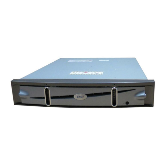
This overview describes the major hardware features of AX4-5 series
storage systems.
For greater clarity, the illustrations in this document show the storage-system
chassis independent of a cabinet or deskside mounting
Topics include
Storage-system components ........................................................... 2
Disk and filler modules.................................................................. 5
Storage processors (SPs)................................................................. 7
Link control cards (LCCs) .............................................................. 8
Power/cooling modules ................................................................ 9
Standby power supplies (SPSs)....................................................... 10
Powerup and powerdown sequence ............................................... 11
Status lights and indicators ............................................................ 15
Hardware and Operational
AX4-5 Series
Overview
January 4, 2010
1
Advertisement

Related Manuals for EMC AX4-5


Summary of Contents for EMC AX4-5
-
Page 1: Table Of Contents
AX4-5 Series Hardware and Operational Overview January 4, 2010 This overview describes the major hardware features of AX4-5 series storage systems. For greater clarity, the illustrations in this document show the storage-system chassis independent of a cabinet or deskside mounting Topics include Storage-system components ............ -
Page 2: Storage-System Components
The AX4-5i and AX4-5SCi storage systems use the Internet Small Computer System Interface (iSCSI) protocol. The AX4-5 and AX4-5SC are also called the AX4-5F and AX4-5FSC, respectively. Models with four Fibre Channel host ports per controller are called AX4–5F8 or AX4–5FX, and AX4–5SCF4 or AX4–5FSCX. - Page 3 − For the AX4-5i or AX4-5SCi, two Gigabit Ethernet (GigE) ports Two power supply/system cooling (power/cooling) modules Figure 1 shows an AX4-5 DPE-AX, which has Fibre Channel I/O modules. Power supply Power/cooling module fault LED cooling fault LED SP service...
- Page 4 AX4-5SCi DPE-AX (rear view) AX4-5 and AX4-5i systems include a standby power supply (SPS); a second SPS is optional. AX4-5 and AX4-5i systems support as many as four optional disk array enclosures (DAE-AXs). Like the DPE-AX, each DAE-AX includes two power/cooling modules and can contain a total of twelve disk drives.
-
Page 5: Disk And Filler Modules
Disk and filler modules Each DPE-AX includes at least four hard disk drives. The first four disks, marked 0-3, are system disks (sometimes called vault disks) and contain vital software specific to the physical slot they occupy in the chassis. Do not move a system disk from its assigned slot to another slot. Remove a system disk only if you need to replace it because it failed. - Page 6 EMC2830 Figure 6 Disk module Disk drives The disk drives are standard 3.5-inch (8.75-cm) by 1.0-inch (2.54-cm) serial advanced technology attachment (SATA) or serial attached SCSI (SAS) drives. AX4–5 systems also support 2.5–inch SAS drives mounted in 3.5–inch drive carriers. For a detailed list of supported disk drives and the minimum revision of the FLARE®...
-
Page 7: Storage Processors (Sps)
Storage processors (SPs) The storage processor (SP) is the storage system’s intelligent component and acts as the input/output (front end) and data storage (back end) control center. Besides the processor board and memory DIMM, each SP includes an I/O module that determines the connection protocol to host servers. -
Page 8: Link Control Cards (Lccs)
Link control cards (LCCs) Optional disk array enclosures (DAE-AXs) do not include SPs, but use link control cards (LCCs) to support additional disk capacity. The LCCs in each DAE-AX connect to expansion ports on SPs or other LCCs with serial-attached SCSI (SAS) expansion cables to create a redundant back-end bus that can support both SATA and SAS drives. -
Page 9: Power/Cooling Modules
Power/cooling modules Each power/cooling module integrates an independent power supply and blowers into a single module. The power supply in each module is an auto-ranging, power-factor-corrected, multi-output, offline converter. The power/cooling modules, A and B, are located above the SPs or LCCs. -
Page 10: Standby Power Supplies (Spss)
Standby power supplies (SPSs) A 1U, 1000-watt SPS provides backup power for power supply A. An optional second SPS supports power supply B. During a power failure, the SPSs allow write caching to continue, which prevents data loss. A faulted or not fully charged SPS disables the write cache. Each SPS rear panel has one AC inlet power connector with power switch, AC outlets for the DPE-AX SPs, and one connector for serial connection to an SP. -
Page 11: Powerup And Powerdown Sequence
Powerup and powerdown sequence A DAE-AX does not have a power switch. It powers up immediately once it is connected to a live power source. Powering up the storage system 1. Verify the following: Master switch/circuit breakers for any cabinet/rack power strip are off. - Page 12 *VVVYYWWRRRRR* *VVVYYWWRRRRR* S/N: VVVYYWWRRRRR S/N: VVVYYWWRRRRR P/N: 118031924 REV: AXX P/N: 118031924 REV: AXX *118031924* *AXX* *118031924* *AXX* *VVVYYWWRRRRR* FRU Label *VVVYYWWRRRRR* FRU Label S/N: VVVYYWWRRRRR S/N: VVVYYWWRRRRR P/N: 118031924 REV: AXX P/N: 118031924 REV: AXX *118031924* *AXX* *118031924* *AXX* 046-003-042_A03 046-003-042_A03 FRU Label...
- Page 13 FRU Label FRU Label CL3766 Figure 11 SP power button The storage system can take 5-6 minutes to complete its powerup. If disk modules 0-3 shipped separately from your DPE-AX, the system writes vital information to those disks during the first powerup. The process extends the first powerup by 25-30 minutes.
- Page 14 storage system management software is available to help you troubleshoot the system. If the power buttons do not remain solid/steady green, contact your authorized service provider. Powering down the storage system CAUTION Never shut down a DPE-AX by disconnecting the AC power cords for its power/cooling modules.
-
Page 15: Status Lights And Indicators
Status lights and indicators Status lights, made up of light emitting diodes (LEDs), indicate each component’s current status. This section describes status lights visible on the DPE-AX, DAE-AX, and SPS. DPE-AX lights and indicators Figure 13 and Table 1 display the status lights visible from the front of a DPE-AX: System Disk drive... - Page 16 Power supply Cooling fault fault Power supply on/off FRU Label FRU Label Fibre SP management SP power SP fault CL3916 Figure 14 DPE-AX lights visible from the rear (2–port Fibre Channel I/O module shown ) Table 2 Meaning of the DPE-AX status lights visible from the rear Quantity State Meaning...
- Page 17 Quantity State Meaning Power supply on/off 1 per power supply Solid green Indicates ac power and normal acitvity No ac power Cooling fault 1 per power Solid amber Indicates a cooling fault supply/system cooling Indicates blower is operating normally module DAE-AX status lights and indicators Figure 15 and Table 3 display the meaning of the status lights on the front of a DAE-AX:...
- Page 18 Power supply fault Power supply connectivity on/off Cooling fault LCC power *VVVYYWWRRRRR* *VVVYYWWRRRRR* S/N: VVVYYWWRRRRR S/N: VVVYYWWRRRRR P/N: 118031924 REV: AXX P/N: 118031924 REV: AXX *118031924* *AXX* *118031924* *AXX* *VVVYYWWRRRRR* *VVVYYWWRRRRR* FRU Label FRU Label S/N: VVVYYWWRRRRR S/N: VVVYYWWRRRRR P/N: 118031924 REV: AXX P/N: 118031924 REV: AXX...
- Page 19 Enclosure number 1 per LCC Flashing dashes Not accessible or initializing at the beginning of powerup Number displayed (solid) Online to Flare Number displayed (blinking) Flare has lost connection with enclosure Standby power supply LEDs Figure 17 and Table 5 display the meaning of the SPS status lights: Active (green) On battery...
- Page 20 Copyright © 2007–2010 EMC Corporation. All Rights Reserved. EMC believes the information in this publication is accurate as of its publication date. The information is subject to change without notice. THE INFORMATION IN THIS PUBLICATION IS PROVIDED "AS IS." EMC CORPORATION...
Need help?
Do you have a question about the AX4-5 and is the answer not in the manual?
Questions and answers