Mitsubishi L3E Service Manual
L-series
Hide thumbs
Also See for L3E:
- Service manual (254 pages) ,
- Operation & maintenance manual (89 pages) ,
- Operation manual (44 pages)
Table of Contents
Advertisement
FOREWORD
This service manual is written to familiarize you with the maintenance of your L-series Diesel Engine. If the engine is
carefully maintained, it will deliver a long productive life and efficient performance marked by power and economy.
Before attempting to inspect, disassemble, or repair the engine, read this manual carefully to learn more about the
engine and how to care for it properly. All descriptions, illustrations, specifications and serial numbers in this manual
are effective as of the date of printing of this manual.
The information contained in this manual applies to the engine model produced at the time of publication. It should
be noted that specifications and design may change due to improvements made thereafter.
What this manual covers
This service manual covers standard specifications for the L-series Mitsubishi Diesel Engine, and describes
•
Specification
•
Maintenance standard
•
Adjustment
•
Disassembly, inspection and repair
•
Reassembly
In addition to the Summary of Manual Contents, a short summary of contents is found on the first page of each
group of the manual.
Operation and periodic maintenance are described in the Operation & Maintenance Manual, component parts and
ordering of service parts are described in the Parts Catalogue. Structure and function of the engine are described in
the various training manuals.
How to use this manual
1.
Parts in illustrations are numbered to correspond with references to those numbers in the disassembly
sequence.
2.
Items or conditions to be inspected during disassembly are enclosed in a box in the disassembled views:
3.
Clogged oil hole
4.
Maintenance standards for inspection and repair are described in text where they are relevant. For a quick
summary of maintenance standards, refer to group 9 of this manual.
5.
Tightening torque under wet conditions is indicated as "(wet)" in text, drawings and tables. When so indicated as
(wet), apply engine oil to the threaded portion of the fastener. Unless indicated as such, the tightening torque is
to be assumed in the dry condition.
6.
Measurements are based on the International System of Units (SI), and they are converted to the metric and
English system units in this manual based on the following conversion rates.
•
Pressure
1 Mpa = 10.197 kgf/cm
•
Torque
N·m = 0.10197 kgf·m
•
Force
N = 0.10197 kgf
•
Horsepower
1 kW = 1.341 HP = 1.3596 PS
Service Manual
Mitsubishi L-Series diesel engines
Version 08/2004
Copyright © 2004 MHI Equipment Europe B.V.
Service Manual Mitsubishi L-Series diesel engines
Version 08/2004
2
ENGLISH
1 / 155
Advertisement
Table of Contents

Related Manuals for Mitsubishi L3E


Summary of Contents for Mitsubishi L3E
-
Page 1: How To Use This Manual
The information contained in this manual applies to the engine model produced at the time of publication. It should be noted that specifications and design may change due to improvements made thereafter. What this manual covers This service manual covers standard specifications for the L-series Mitsubishi Diesel Engine, and describes • Specification •... - Page 2 Some of the CAUTION signs also indicate a specific potential hazard which could result in serious personal injury or death. Indicates procedures, conditions, etc. which are important to highlight. NOTE 2 / 155 ENGLISH Service Manual Mitsubishi L-Series diesel engines Version 08/2004...
- Page 3 The value is rounded to the nearest number needed for inspection and is different from the design value. Repair limit A part which has reached this limit must be repaired. Service limit A part which has reached this limit must be replaced. ENGLISH 3 / 155 Service Manual Mitsubishi L-Series diesel engines Version 08/2004...
-
Page 4: English Service Manual Mitsubishi L-Series Diesel Engines
General, starter, alternator and dynamo, glow plug, key-off stop system, glow timer system Service Periodic service chart, specifications and standards, tightening torque chart and sealant chart, specifications and special tools standard Table 1 Sections in the service manual 4 / 155 ENGLISH Service Manual Mitsubishi L-Series diesel engines Version 08/2004... -
Page 5: Table Of Contents
................42 Disassembly........................... 42 Removal and installation......................43 Inspection..........................43 CYLINDER HEAD ........................44 Disassembly........................... 44 Removal..........................45 Inspection and Repair ......................46 Replacement of valve guide....................46 Service Manual Mitsubishi L-Series diesel engines ENGLISH 5 / 155 Version 08/2004... - Page 6 16.4 Replacement of crankshaft rear oil seal................. 76 16.5 Installation..........................77 CYLINDER BLOCK ........................78 17.1 Disassembly........................... 78 17.2 Inspection..........................79 17.3 Reboring of cylinder ....................... 79 LUBRICATION SYSTEM 6 / 155 ENGLISH Service Manual Mitsubishi L-Series diesel engines Version 08/2004...
- Page 7 24.5 Removal and installation...................... 103 COOLING SYSTEM GENERAL ..........................106 25.1 Specifications........................106 25.2 Disassembly......................... 107 FAN AND FAN BELT ......................108 26.1 Fan belt inspection....................... 108 26.2 Fan inspection........................108 ENGLISH 7 / 155 Service Manual Mitsubishi L-Series diesel engines Version 08/2004...
- Page 8 35.2 Control timer unit........................138 35.3 Fuel cutoff solenoid (ETS type).................... 138 35.4 Fuel cutoff solenoid (ETR type) ................... 139 GLOW TIMER SYSTEM ......................141 36.1 General ..........................141 8 / 155 ENGLISH Service Manual Mitsubishi L-Series diesel engines Version 08/2004...
- Page 9 39.1 Tightening Torque for Main Bolts..................152 39.2 Tightening Torque for Common Bolts and Nuts..............152 39.3 Tightening Torque for Common Plugs ................. 153 39.4 Sealant Chart ........................153 SPECIAL TOOLS ........................154 ENGLISH 9 / 155 Service Manual Mitsubishi L-Series diesel engines Version 08/2004...
- Page 10 10 / 155 ENGLISH Service Manual Mitsubishi L-Series diesel engines Version 08/2004...
- Page 11 GENERAL ENGLISH 11 / 155 Service Manual Mitsubishi L-Series diesel engines Version 08/2004...
-
Page 12: General
The engine model and cylinder volume are embossed on the side of injection pump mounting portion of the cylinder block. Figure 1 Engine model and cylinder volume 12 / 155 ENGLISH Service Manual Mitsubishi L-Series diesel engines Version 08/2004... - Page 13 It is a serial number beginning with 1001 shown as below. Number Engine model 1001 - (ALL models) Table 2 Engine number stamp Figure 2 Engine number Service Manual Mitsubishi L-Series diesel engines ENGLISH 13 / 155 Version 08/2004...
-
Page 14: External View
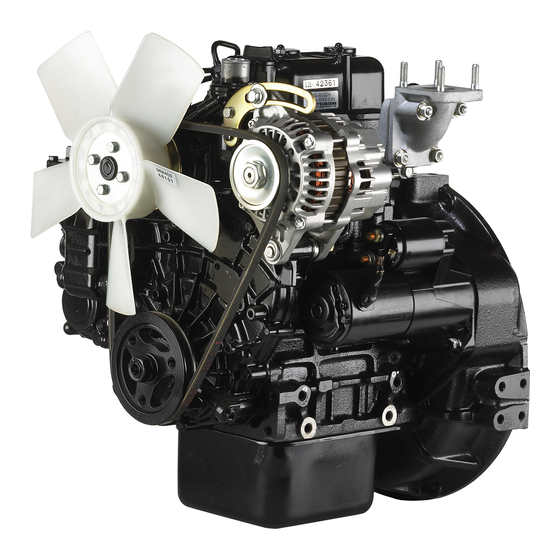
REAR FRONT RIGHT SIDE VIEW Top oil filler Thermostat housing Exhaust manifold Thermoswitch Flywheel housing Alternator Flywheel Starter V-belt Crankshaft pulley Oil pan REAR FRONT LEFT SIDE VIEW 14 / 155 ENGLISH Service Manual Mitsubishi L-Series diesel engines Version 08/2004... -
Page 15: Engine L3
REAR FRONT RIGHT SIDE VIEW Top oil filler Thermostat housing Exhaust manifold Thermoswitch Flywheel housing Flywheel Alternator Starter V-belt Crankshaft pulley Oil pan FRONT REAR LEFT SIDE VIEW Service Manual Mitsubishi L-Series diesel engines ENGLISH 15 / 155 Version 08/2004... -
Page 16: Features
“full throttle” position. Figure 3 Injection pump 16 / 155 ENGLISH Service Manual Mitsubishi L-Series diesel engines Version 08/2004... - Page 17 The L-series engine can be equipped with various kinds of optional devices. • Key-OFF stop system (Fuel cutoff valve) • Torque spring • Manual stop lever Figure 4 Nozzle holders and return pipe Service Manual Mitsubishi L-Series diesel engines ENGLISH 17 / 155 Version 08/2004...
-
Page 18: Specifications
12V, 45 Ah or more 12V, 60 Ah or more (capacity depends on application) Table 3 Specifications 1 All specifications are subject to change without any prior notice. 18 / 155 ENGLISH Service Manual Mitsubishi L-Series diesel engines Version 08/2004... -
Page 19: Maintenance
(whatever comes first) can be applied for industrial and marine application. 5.1.3 Engine oil to be used Engine oil must conform to the API classification and viscosity number specified in the table below. Service Manual Mitsubishi L-Series diesel engines ENGLISH 19 / 155 Version 08/2004... - Page 20 [0.9511/0.4756] or 1 [U.S.gal] 4.8/3.0 [1.2682/ 0.7926] Table 6 Oil capacity 5.1.6 Replacing the oil filter Procedure Remove the oil filter with a filter wrench or the like. 20 / 155 ENGLISH Service Manual Mitsubishi L-Series diesel engines Version 08/2004...
-
Page 21: Retightening The Cylinder Head Bolts
The rocker assembly (the rocker arms, shaft and stays) Figure 9 Cylinder head bolt tightening sequence is to be kept removed when the cylinder head bolts are (L3) retightened. Service Manual Mitsubishi L-Series diesel engines ENGLISH 21 / 155 Version 08/2004... -
Page 22: Adjusting The Valve Clearance
No. 2 cylinder, to set the No. 3 cylinder TDC. Further, turn the crankshaft 240° clockwise from No. 3 cylinder TDC and reconfirm the position of the No. 2 cylinder TDC. 22 / 155 ENGLISH Service Manual Mitsubishi L-Series diesel engines Version 08/2004... -
Page 23: Adjusting The Fan Belt Tension
Air in the injection pipes and nozzles is driven out automatically by cranking the engine. Figure 14 Fuel injection pump air bleeding Service Manual Mitsubishi L-Series diesel engines ENGLISH 23 / 155 Version 08/2004... -
Page 24: Replacing The Fuel Filter
Magnet Cover Figure 16 Plunger type (common) fuel pump Figure 17 Plunger type (compact) fuel pump 24 / 155 ENGLISH Service Manual Mitsubishi L-Series diesel engines Version 08/2004... - Page 25 For engine provided with a water sedimentator, remove the filter ring nut involved and take out the cup. Wipe off water and dust accumulated in the cup. Service Manual Mitsubishi L-Series diesel engines ENGLISH 25 / 155 Version 08/2004...
-
Page 26: Checking And Adjusting Injection Timing
Increasing or decreasing shim thickness by 0.1 mm [0.0039 in.] causes the real injection timing to vary about 1°. Figure 22 Adjusting shim thickness 26 / 155 ENGLISH Service Manual Mitsubishi L-Series diesel engines Version 08/2004... -
Page 27: Adjusting The Engine Speeds
60°C [140°F] or above) before adjusting engine speeds. During running of the engine for speed adjustment, check the engine for gas leak, water leak, oil leak and fuel leak. Service Manual Mitsubishi L-Series diesel engines ENGLISH 27 / 155 Version 08/2004... -
Page 28: Checking And Adjustment Of Nozzles
(3.5 to 4.0 kgf·m) [25.32 to 28.93 lbf·ft] Nozzle union collar 25 to29 N·m tightening torque (2.5 to 3.0 kgf·m) [18.08 to 21.70 lbf·ft] Table 14 Tightening torque 28 / 155 ENGLISH Service Manual Mitsubishi L-Series diesel engines Version 08/2004... -
Page 29: Checking The Compression Pressure
Pull the stop lever to the “non-injection” position. Remove the glow plug from the cylinder to be tested. Set the compression gage adapter to that cylinder and install the gage. Service Manual Mitsubishi L-Series diesel engines ENGLISH 29 / 155 Version 08/2004... - Page 30 After reading the gage, remove the compression gage and adapter. Put back the glow plug. Check all cylinders using the same procedure described above. 30 / 155 ENGLISH Service Manual Mitsubishi L-Series diesel engines Version 08/2004...
-
Page 31: Troubleshooting
Compare the degree of slowdown with the other cylinders. Service Manual Mitsubishi L-Series diesel engines ENGLISH 31 / 155 Version 08/2004... -
Page 32: Hard Starting
Inspect injection nozzles. State of fuel spray and injection starting pressure. Inspect valves, pistons, piston Is cylinder compression pressure proper? rings and cylinder head gasket. Inspect injection pump. 32 / 155 ENGLISH Service Manual Mitsubishi L-Series diesel engines Version 08/2004... -
Page 33: Knocking
Is cylinder compression proper? rings and cylinder head gasket. Does injection pump operate properly? (Check for uniformity of injection quantity.) Mechanical noise (Worn or damaged main moving parts) Service Manual Mitsubishi L-Series diesel engines ENGLISH 33 / 155 Version 08/2004... -
Page 34: Overheating
60°C or lower than ambient temperature. If it exceeds, it is recommended to check other factors than engine main parts. 34 / 155 ENGLISH Service Manual Mitsubishi L-Series diesel engines Version 08/2004... -
Page 35: Black-Smoky Exhaust
(Check for improper shape of fuel spray and for excessively high injection Inspect injection nozzles. starting pressure.) Inspect valves, cylinder head Is cylinder compression proper? gasket, pistons, and piston rings. Inspect injection pump. Service Manual Mitsubishi L-Series diesel engines ENGLISH 35 / 155 Version 08/2004... -
Page 36: Unsteady Idling
(Check for shape of fuel spray and injection starting pressure.) Is cylinder compression pressure proper? Inspect valves, pistons and (Check equality between cylinders.) piston rings. Inspect injection pump and governor system. 36 / 155 ENGLISH Service Manual Mitsubishi L-Series diesel engines Version 08/2004... -
Page 37: Low Output
Inspect injection nozzles. (Check for condition of fuel mist injection and injection starting pressure.) Inspect valves, cylinder head Is cylinder compression proper? gasket, pistons and piston rings. Inspect injection pump. Service Manual Mitsubishi L-Series diesel engines ENGLISH 37 / 155 Version 08/2004... - Page 38 TROUBLESHOOTING GENERAL 38 / 155 ENGLISH Service Manual Mitsubishi L-Series diesel engines Version 08/2004...
-
Page 39: Engine Main Parts
ENGINE MAIN PARTS ENGLISH 39 / 155 Service Manual Mitsubishi L-Series diesel engines Version 08/2004... -
Page 40: General
Main journal dia. x Crankpin dia. 43 x 40 [1.6929 x 1.5748] mm [in.] Type “Autothermic” PISTON Joint to connecting rod Semi-floating Cooling Oil jet Table 17 Specifications 40 / 155 ENGLISH Service Manual Mitsubishi L-Series diesel engines Version 08/2004... -
Page 41: Special Tools
For L2C, L3C: 30L91-00020 For L2E, L3E: 30L91-10010 Compression gage adapter ST332270 Measurement of cylinder compression Piston ring pliers 31391-12900 Removing and installing piston ring Table 18 Special tools Service Manual Mitsubishi L-Series diesel engines ENGLISH 41 / 155 Version 08/2004... -
Page 42: Rocker Arms And Rocker Shaft
ROCKER SHAFT Disassembly Figure 30 Rocker system components parts Disassembly sequence Oil filter cap Breather hose Rocker cover Rocker cover gasket Rocker shaft Rocker spring Adjust screw Rocker arm 42 / 155 ENGLISH Service Manual Mitsubishi L-Series diesel engines Version 08/2004... -
Page 43: Removal And Installation
Installing rocker shaft and rocker cover Inspection Check the rocker shaft and rocker arms. If any defective parts are found, replace them. Figure 32 Inspecting rocker shaft and rocker arms Service Manual Mitsubishi L-Series diesel engines ENGLISH 43 / 155 Version 08/2004... -
Page 44: Cylinder Head
Valve guide Cylinder head bolt (main bolt) Cylinder head bolt (sub-bolt) Seat ring (3600 min specification engine) Water outlet fitting Cylinder head gasket Mouth piece Thermostat 10. Thermostat fitting 44 / 155 ENGLISH Service Manual Mitsubishi L-Series diesel engines Version 08/2004... -
Page 45: Removal
After removing the pipe assembly, place a cap to the nozzle holders and delivery valve holders to prevent from entering the dust. Figure 36 Removing valves 12. Remove the valve stem seals. Service Manual Mitsubishi L-Series diesel engines ENGLISH 45 / 155 Version 08/2004... -
Page 46: Inspection And Repair
Press-fit the guide from the upper side of the cylinder head to a height of 14 ±0.5 mm [0.5512 ±0.0197 in.] from the valve spring seat face. Figure 38 Press-fitting valve guide 46 / 155 ENGLISH Service Manual Mitsubishi L-Series diesel engines Version 08/2004... -
Page 47: Service Manual Mitsubishi L-Series Diesel Engines English
Resurface the valve seat so that it contacts the mid-portion of the valve face. Figure 40 Refacing valve seat (Both inlet and exhaust valves) Service Manual Mitsubishi L-Series diesel engines ENGLISH 47 / 155 Version 08/2004... -
Page 48: Installation
Also, be careful not to allow dust to enter the fuel line. Figure 42 Sequence for tightening cylinder head bolts (L3) 48 / 155 ENGLISH Service Manual Mitsubishi L-Series diesel engines Version 08/2004... -
Page 49: Valves And Valve Springs
10.1 Disassembly (Not installed to agricultural model) Figure 43 Valve system component parts Disassembly sequence Valve stem cap Valve lock Valve spring retainer Valve stem seal Valve spring Valve Service Manual Mitsubishi L-Series diesel engines ENGLISH 49 / 155 Version 08/2004... -
Page 50: Removal
[in.] Figure 45 Inspection of valve and valve spring Perpendicularity 2° 3° Margin mm [in.] [0.0394] [0.0197] Table 20 Valve inspection and repair Figure 46 Valve spring tester 50 / 155 ENGLISH Service Manual Mitsubishi L-Series diesel engines Version 08/2004... -
Page 51: Installation
Driving in stem seal Figure 48 Installation of valve spring CAUTION Be careful not to damage the spring and stem seal by excessively pushing the spring when installing the valve spring. Service Manual Mitsubishi L-Series diesel engines ENGLISH 51 / 155 Version 08/2004... -
Page 52: Inlet Manifold And Exhaust Manifold
Inlet pipe Inlet manifold Exhaust manifold Inlet manifold gasket Exhaust manifold gasket 11.2 Inspection Check the following matters. If any defect is found, repair or replace the manifold. 52 / 155 ENGLISH Service Manual Mitsubishi L-Series diesel engines Version 08/2004... - Page 53 Check the interior of the inlet manifold for dust and dirt. If any dust is found, check the joints of the air cleaner and inlet pipe for sealed condition. ENGLISH 53 / 155 Service Manual Mitsubishi L-Series diesel engines Version 08/2004...
-
Page 54: Gear Case And Oil Pump
Front oil seal Relief plunger Relief spring Oil pump inner gear Oil pump outer gear Oil pump housing 10. Gear case gasket 11. High-pressure pump gear housing 12. Housing gasket 54 / 155 ENGLISH Service Manual Mitsubishi L-Series diesel engines Version 08/2004... -
Page 55: Removal
0.20 (1.5) (2.0) (kgf/cm2) [psi] [21] [28] Discharge Flow rate 3 [0.79] 8 [4.76] l [U.S.gal]/min more more Table 21 Oil pump performance, oil used: SAE30, 100±5°C [212±9°F] Service Manual Mitsubishi L-Series diesel engines ENGLISH 55 / 155 Version 08/2004... -
Page 56: Replacement Of Front Oil Seal
Press-fit the new bushings into the positions shown at right. +0.20 +0.0079 [1.6142 in.] To be flush with To be in contact this place with bottom Figure 52 Press-fitting governor shaft bushing 56 / 155 ENGLISH Service Manual Mitsubishi L-Series diesel engines Version 08/2004... -
Page 57: Inspection Of Governor System
Reassemble the shaft in the reverse sequence of disassembly. After reassembling the shaft, press-fit the Figure 54 Reassembling governor shaft expansion plug into the shaft hole in the gear case. Service Manual Mitsubishi L-Series diesel engines ENGLISH 57 / 155 Version 08/2004... -
Page 58: Installation Of Gear Case Assembly
14.7 to 21.6 N·m (1.5 to 2.2 kgf·m) [10.85 to 15.91 lbf·ft] Sealant: HERMESEAL H1 or THREE-BOND 1344 Figure 55 Gear case assembly Figure 56 Installing gear case assembly 58 / 155 ENGLISH Service Manual Mitsubishi L-Series diesel engines Version 08/2004... -
Page 59: Timing Gears
TIMING GEARS ENGINE MAIN PARTS 13 TIMING GEARS 13.1 Disassembly Figure 57 Timing gear component parts Disassembly sequence Crankshaft gear Idle gear Camshaft gear Injection pump camshaft gear Service Manual Mitsubishi L-Series diesel engines ENGLISH 59 / 155 Version 08/2004... -
Page 60: Removal
[0.0004 to 0.0055] [0.0118] Idle-fuel Valve camshaft gear Crankshaft gear pump gear Figure 60 Inspecting timing gears Table 23 Backlash between gears after installation, unit in mm [in.] 60 / 155 ENGLISH Service Manual Mitsubishi L-Series diesel engines Version 08/2004... -
Page 61: Installation Of Timing Gears
Install the valve camshaft and injection pump camshaft. Install the idle gear aligning with the timing marks of other gears. Confirm the positions of timing gears again. Figure 61 Timing gears in alignment Service Manual Mitsubishi L-Series diesel engines ENGLISH 61 / 155 Version 08/2004... -
Page 62: Camshafts (Valve And Injection Pump)
Camshaft gear Ball bearing (Front) Woodruff key Sunk key Camshaft stopper washer Bolt Tappet Pushrod 10. Camshaft (Injection pump) 11. Camshaft gear 12. Ball bearing (Rear) 13. Snap ring 62 / 155 ENGLISH Service Manual Mitsubishi L-Series diesel engines Version 08/2004... -
Page 63: Removal Of Valve Camshaft
Remove the gear case assembly. Remove the shaft rear cover. Remove the stopper bolt. Pull out the shaft to the front side. Figure 63 Removing injection pump camshaft ENGLISH 63 / 155 Service Manual Mitsubishi L-Series diesel engines Version 08/2004... -
Page 64: Inspection
Major diameter of injection -0.7 pump cam [1.1811] [-0.0276] Major diameter of valve cam 27.37 -1.0 [1.0776] [-0.0394] Table 24 Inspection of camshafts, unit in mm [in.] 64 / 155 ENGLISH Service Manual Mitsubishi L-Series diesel engines Version 08/2004... -
Page 65: Installation
Align the timing marks on the gears to the marks on the idler gear. After installation, check and adjust fuel injection timing and valve clearances. Figure 65 Installing valve camshaft ENGLISH 65 / 155 Service Manual Mitsubishi L-Series diesel engines Version 08/2004... -
Page 66: Piston And Connection Rod
Piston ring No. 1 Piston ring No. 2 Oil ring Piston Piston pin Connecting rod Connecting rod bearing Connecting rod cap Connecting rod bolt 10. Connecting rod nut 66 / 155 ENGLISH Service Manual Mitsubishi L-Series diesel engines Version 08/2004... -
Page 67: Removal
Part No. for L2A, L3A, 30L91–00030 Figure 68 Removing piston pin Piston pin setting for L2C, L3C, 30L91–00020 tool for L2E. L3E, 30L91–10010 Table 26 Piston pin setting tool Service Manual Mitsubishi L-Series diesel engines ENGLISH 67 / 155 Version 08/2004... -
Page 68: Inspection
No. 2 [0.0059 to 0.0118] Ring gaps 1.5 [0.059] 0.15 to 0.35 Figure 70 Measuring ring gap [0.0059 to 0.0138] Table 27 Inspection of camshafts, unit in mm [in.] 68 / 155 ENGLISH Service Manual Mitsubishi L-Series diesel engines Version 08/2004... -
Page 69: Installation
Special tool Part No. Piston pin setting tool ST332400 Table 29 Piston pin setting tool Figure 72 Installation of piston and connecting rod Service Manual Mitsubishi L-Series diesel engines ENGLISH 69 / 155 Version 08/2004... - Page 70 FRONT mark (arrow) Piston Guide Tool body Base plug Guide “LA” (92 l): for L2A, L3A Guide “LC” (89.5 l): for L2C, L2E, L3C, L3E Figure 73 Reassembling piston pin 70 / 155 ENGLISH Service Manual Mitsubishi L-Series diesel engines...
- Page 71 No. 2 ring gap Coil expanded joint of oil ring Figure 75 Proper arrangement of ring gaps Service Manual Mitsubishi L-Series diesel engines ENGLISH 71 / 155 Version 08/2004...
- Page 72 (provided for preventing the bearing from rotating) on the same side. Figure 76 Fitting cap to connecting rod 72 / 155 ENGLISH Service Manual Mitsubishi L-Series diesel engines Version 08/2004...
-
Page 73: Crankshaft
Crankshaft component parts Disassembly sequence Crankshaft Crankshaft gear Crankshaft pulley Washer Spring washer Flywheel Ring gear 10. Rear oil seal 11. Rear oil seal case 12. Gasket 13. Flywheel bolt Service Manual Mitsubishi L-Series diesel engines ENGLISH 73 / 155 Version 08/2004... -
Page 74: Removal
• Wear of journal contact surface Wobble Damage to tooth face Damage to tooth face Wear and damage Wobble of pulley Figure 79 Inspection of crankshaft and flywheel 74 / 155 ENGLISH Service Manual Mitsubishi L-Series diesel engines Version 08/2004... - Page 75 Figure 81 Measuring main bearing I. D. corresponding under size. CAUTION A crankshaft, which has been seized, cannot be reground to any under size. Service Manual Mitsubishi L-Series diesel engines ENGLISH 75 / 155 Version 08/2004...
-
Page 76: Replacement Of Crankshaft Rear Oil Seal
Pry the oil seal out with a screwdriver. Drive in a new oil seal to the oil seal case. 76 / 155 ENGLISH Service Manual Mitsubishi L-Series diesel engines Version 08/2004... -
Page 77: Installation
Round end down Place cap flush with the end face of cylinder block. Crankshaft end play: 0.05 to 0.175 mm [0.0020 to 0.0069 in.] Figure 82 Installation of crankshaft Service Manual Mitsubishi L-Series diesel engines ENGLISH 77 / 155 Version 08/2004... -
Page 78: Cylinder Block
Cylinder block Front plate Bearing cap Cover Main bearing Starter bracket Rear oil seal Oil seal case Idler gear shaft 10. Oil filter shaft 11. Oil level gage guide 78 / 155 ENGLISH Service Manual Mitsubishi L-Series diesel engines Version 08/2004... -
Page 79: Inspection
Measuring piston diameter CAUTION When it is necessary for a cylinder to be rebored to the next over size, other cylinders must also be rebored to the same over size. Service Manual Mitsubishi L-Series diesel engines ENGLISH 79 / 155 Version 08/2004... - Page 80 CYLINDER BLOCK ENGINE MAIN PARTS 80 / 155 ENGLISH Service Manual Mitsubishi L-Series diesel engines Version 08/2004...
-
Page 81: Lubrication System
LUBRICATION SYSTEM ENGLISH 81 / 155 Service Manual Mitsubishi L-Series diesel engines Version 08/2004... -
Page 82: General
18.2 Special tools Tool name Part No Shape Removal and installation of oil pressure switch Socket wrench MD998054 1. All specifications are subject to change without any prior notice. 82 / 155 ENGLISH Service Manual Mitsubishi L-Series diesel engines Version 08/2004... -
Page 83: Oil Filter And Oil Pressure Switch
OIL FILTER AND OIL PRESSURE SWITCH LUBRICATION SYSTEM 19 OIL FILTER AND OIL PRESSURE SWITCH 19.1 Disassembly Figure 87 Oil filter and pressure switch Disassembly sequence Oil filter Oil pressure switch Service Manual Mitsubishi L-Series diesel engines ENGLISH 83 / 155 Version 08/2004... -
Page 84: Removal And Installation
Table 39 Pressure CAUTION Check the oil filter for contamination. If necessary, clean the engine interior with flushing oil. Figure 90 Inspecting oil filter and oil pressure switch 84 / 155 ENGLISH Service Manual Mitsubishi L-Series diesel engines Version 08/2004... -
Page 85: Fuel System
FUEL SYSTEM ENGLISH 85 / 155 Service Manual Mitsubishi L-Series diesel engines Version 08/2004... -
Page 86: General
0.4 l/min [0.1057 U.S.gal/min] (12V, at 20°C [68°F]) Type Mechanical drive type Delivery 0.225 l [0.0594 U.S.gal]/min Table 40 Specifications 1. All specifications are subject to change without any prior notice. 86 / 155 ENGLISH Service Manual Mitsubishi L-Series diesel engines Version 08/2004... - Page 87 1.6Ω±10% (at 20°C [68°F]) Stroke 10 mm [0.3937 in.] FUEL FILTER Paper-element type Table 40 Specifications a. Please refer to the applicable engine model specification sheet for actual data Service Manual Mitsubishi L-Series diesel engines ENGLISH 87 / 155 Version 08/2004...
-
Page 88: Disassembly
GENERAL FUEL SYSTEM 20.2 Disassembly Figure 91 Fuel system component parts Disassembly sequence Injection pump Adjusting shim Injection pipe Injection nozzle Return pipe Fuel filter Fuel cutoff solenoid 88 / 155 ENGLISH Service Manual Mitsubishi L-Series diesel engines Version 08/2004... -
Page 89: Fuel Injection Pump
12. Sleeve 13. Upper seat 14. Plunger spring 15. Plunger 16. Lower seat 17. Adjusting shim 18. Tappet roller 19. Pin 20. Control rack 21. Stop wire bracket Service Manual Mitsubishi L-Series diesel engines ENGLISH 89 / 155 Version 08/2004... -
Page 90: Inspecting The Injection Pump While Operating The Engine
All removed parts from the pump should be classified by cylinders and immersed in clean fuel. 90 / 155 ENGLISH Service Manual Mitsubishi L-Series diesel engines Version 08/2004... -
Page 91: Inspection
(engage the feed Figure 96 Installation of delivery valve holder hole with the plunger lead). After installation, check for proper injection timing. Service Manual Mitsubishi L-Series diesel engines ENGLISH 91 / 155 Version 08/2004... -
Page 92: Injection Nozzle
Nozzle holder assembly component parts Disassembly sequence Body sub-assembly Shim washer Pressure spring Distance piece Nozzle assembly Retaining nut 22.2 Removal Disconnect the injection pipe and fuel return pipe. 92 / 155 ENGLISH Service Manual Mitsubishi L-Series diesel engines Version 08/2004... -
Page 93: Disassembly
Scrape off carbon deposit with a wooden piece. Keep the removed parts immersed in washing oil (kerosene). Pay special attention not to scratch the needle valve in the nozzle assembly. Service Manual Mitsubishi L-Series diesel engines ENGLISH 93 / 155 Version 08/2004... -
Page 94: Inspection
10 kinds of shims available from 1.25 mm to 1.7 mm [0.0492 to 0.0669 in.] in thickness, in increment of 0.05 mm [0.0020 in.]. Figure 100 Testing nozzle 94 / 155 ENGLISH Service Manual Mitsubishi L-Series diesel engines Version 08/2004... -
Page 95: Installation
24.5 to 29.4 N·m 24.5 to 29.4 N·m (2.5 to 3.0 kgf·m) (2.5 to 3.0 kgf·m) [18.08 to 21.70 lbf·ft] [18.08 to 21.70 lbf·ft] Figure 102 Installing injection pipe Service Manual Mitsubishi L-Series diesel engines ENGLISH 95 / 155 Version 08/2004... - Page 96 INJECTION NOZZLE FUEL SYSTEM 96 / 155 ENGLISH Service Manual Mitsubishi L-Series diesel engines Version 08/2004...
-
Page 97: Governor System
GOVERNOR SYSTEM ENGLISH 97 / 155 Service Manual Mitsubishi L-Series diesel engines Version 08/2004... -
Page 98: General
GENERAL GOVERNOR SYSTEM GOVERNOR SYSTEM 23 GENERAL 23.1 Specification Governor type Centrifugal flyweight type Table 43 Specification 98 / 155 ENGLISH Service Manual Mitsubishi L-Series diesel engines Version 08/2004... -
Page 99: Disassembly
21. Stop lever assembly 22. O-ring 23. Snap ring 24. Stop lever 25. Grooved pin (3 x 20) 26. Grooved pin (3 x 16) 27. Torque spring set 28. Sealing cap Service Manual Mitsubishi L-Series diesel engines ENGLISH 99 / 155 Version 08/2004... -
Page 100: Torque Spring
Number of loosening turns L2A-61DA, L2A-62A, L2A-62DA, L2A-61DM L3A-61DA, L3C-63WM L2C-61RR, L2E-61IR, L3A-62DA, L3C-61ES L2A-61A, L2A-61RR, L2A-61SS, L2A-62SS, L2A-62SDG, L2C-62A, L2C-62DA, L2E-62WM, L2E-W262WM, L3A-61A, L3A-62A, L3A-61BG, L3A-61RG, L3C-61A, L3C-62A, L3C-61DA, L3C-61RT 100 / 155 ENGLISH Service Manual Mitsubishi L-Series diesel engines Version 08/2004... -
Page 101: Single Spring Type
L2C-61A, L2C-61CV, L2C2-61CV, L2E-61R, L2E-61SC, L2E-61SDG, L2E-61GS, L2E-W264SGHM, L2E-61DPH, L2E-61DPHA, L2E- W261DPH, L2E-W261DPHA, L2E-W262SDH, L2E-W262WMG, L2E- 62APH2, L3A-61TG, L3A-61ES, L3C-61TG, L3C-62DA, L3C2-62TG, L3E-61R, L3E-61TG, L3E-W261TG, L3E-61RG, L3E-W264SGHM, L3E- 61DPH, L3E-61DPHA, L3E-W261DPH, L3E-W261SPHA, L3E-62APH, L3E-62APH2 L2C-61DM, L2E-61TM, L2E-62A, L2E-62DA, L2E-61ES, L2E-61RR,... -
Page 102: Inspection
L3E-61DA, L3E-31NSA, L3E2-61ES, L3E2-62ES, Green L3E2-63ES, L2E-61GS, L3E2-63ESA, L2A-61DA, L2E–61ES, L2E–61DA L2E–62PL 1520 1520 1500 L3E-61TG, L3A-61A, L3C-61A, L3C-61TG, L3E-61A, L3E-61SC, L3E-61SA, L3E-61DS, L3E-61SHS, L3E-61LS, L3E-61KL, L2A-61A, L2C-61A, L2C-61CV, Yellow L2E-61A, L2E-61SC, L2E-61SA, L2E-61WH, L2E–61HMG, L2E–61IR L3C2–62TG, L3E2–62TG, L3A–61RG, L3E–61RG 1270... -
Page 103: Removal And Installation
Install the governor spring lever and speed Figure 109 Installing speed control lever control lever so that play of angle between levers (standard: 5½ degrees) is minimized. Service Manual Mitsubishi L-Series diesel engines ENGLISH 103 / 155 Version 08/2004... - Page 104 TORQUE SPRING GOVERNOR SYSTEM 104 / 155 ENGLISH Service Manual Mitsubishi L-Series diesel engines Version 08/2004...
-
Page 105: Cooling System
COOLING SYSTEM ENGLISH 105 / 155 Service Manual Mitsubishi L-Series diesel engines Version 08/2004... -
Page 106: General
70°C [158°F]/104±13.5 W Gage specification TEMPERATURE 115°C [239°F]/23.8±2.5 W GAGE UNIT Voltage used 12 volt DC Table 45 Specifications 1. All specifications are subject to change without any prior notice 106 / 155 ENGLISH Service Manual Mitsubishi L-Series diesel engines Version 08/2004... -
Page 107: Disassembly
COOLING SYSTEM GENERAL 25.2 Disassembly Figure 110 Cooling system component parts Disassembly sequence Cooling fan Water pump pulley Water pump assembly V-belt Thermostat Thermostat fitting Thermoswitch Bypass pipe Service Manual Mitsubishi L-Series diesel engines ENGLISH 107 / 155 Version 08/2004... -
Page 108: Fan And Fan Belt
Figure 111 Inspecting fan belt 26.2 Fan inspection Check the fan for cracks, damage and deformation. If any, replace the fan. Figure 112 Inspecting fan 108 / 155 ENGLISH Service Manual Mitsubishi L-Series diesel engines Version 08/2004... -
Page 109: Water Pump
27.2 Inspection Check the water pump for water leak, improper rotation Figure 113 Removing water pump and cracks. If any, replace the water pump assembly Service Manual Mitsubishi L-Series diesel engines ENGLISH 109 / 155 Version 08/2004... -
Page 110: Thermostat
76.5°C 71°C [169.7°F] [159.8°F] Valve cranking 76.5±1.5°C 71°C temperature [169.7±2.7°F] [159.8°F] Full-open temperature 90±1.5°C 85°C Figure 115 Inspecting thermostat (lift 6 mm) [194±2.7°F] 185°F] Table 46 Inspection thermostat 110 / 155 ENGLISH Service Manual Mitsubishi L-Series diesel engines Version 08/2004... -
Page 111: Water Temperature Gage Unit And Thermoswitch
Switch-ON 111±3.5°C [231.8±6.3°F] temperature Table 48 Inspecting thermoswitch CAUTION Take special care when handling hot oil in order not to cause burns or fire. Figure 117 Inspecting thermoswitch ENGLISH 111 / 155 Service Manual Mitsubishi L-Series diesel engines Version 08/2004... - Page 112 WATER TEMPERATURE GAGE UNIT AND THERMOSWITCH COOLING SYSTEM 112 / 155 ENGLISH Service Manual Mitsubishi L-Series diesel engines Version 08/2004...
-
Page 113: Air Cleaner
AIR CLEANER ENGLISH 113 / 155 Service Manual Mitsubishi L-Series diesel engines Version 08/2004... -
Page 114: Air Cleaner
AIR CLEANER AIR CLEANER AIR CLEANER 30 AIR CLEANER 30.1 Disassembly Figure 118 Air cleaner component parts Disassembly sequence Body assembly Element assembly Dust pan assembly Bolt Partition plate 114 / 155 ENGLISH Service Manual Mitsubishi L-Series diesel engines Version 08/2004... -
Page 115: Inspection
When installing the air cleaner, properly place it so that the air inlet opening faces sideward or downward. Also, install the dust pan following the arrow marked “TOP”. Service Manual Mitsubishi L-Series diesel engines ENGLISH 115 / 155 Version 08/2004... -
Page 116: Air Cleaner Air Cleaner
AIR CLEANER AIR CLEANER 116 / 155 ENGLISH Service Manual Mitsubishi L-Series diesel engines Version 08/2004... -
Page 117: Electrical System
ELECTRICAL SYSTEM ENGLISH 117 / 155 Service Manual Mitsubishi L-Series diesel engines Version 08/2004... -
Page 118: General
DC 9 to 15 TIMER UNIT Solenoid (resistance in coil: 1.7 Ω minimum) Load Table 49 Specifications 1. All specifications are subject to change without any prior notice. 118 / 155 ENGLISH Service Manual Mitsubishi L-Series diesel engines Version 08/2004... - Page 119 Operating temperature range °C (°F) -30 to +70 (-22 to 158) Storage temperature range °C (°F) -40 to +80 (-40 to 176) Pre-glow time, second 6.2 ± 0.7 Table 49 Specifications Service Manual Mitsubishi L-Series diesel engines ENGLISH 119 / 155 Version 08/2004...
-
Page 120: Wiring Diagrams
GENERAL ELECTRICAL SYSTEM 31.2 Wiring diagrams < ETS type stop solenoid > 120 / 155 ENGLISH Service Manual Mitsubishi L-Series diesel engines Version 08/2004... - Page 121 ELECTRICAL SYSTEM GENERAL < ETR type stop solenoid > Service Manual Mitsubishi L-Series diesel engines ENGLISH 121 / 155 Version 08/2004...
-
Page 122: Starter
Spring set Center bracket assembly Switch assembly Through bolt Armature Rear bearing Pinion 10. Pinion shaft assembly 11. Gear 12. Yoke assembly 13. Brush holder assembly 14. Rear bracket 122 / 155 ENGLISH Service Manual Mitsubishi L-Series diesel engines Version 08/2004... -
Page 123: Inspection (Assembly)
32.2.3 Magnetic switch Perform the following tests. If any defect is found, replace the magnetic switch assembly. Disconnect wire from terminal “M”. Service Manual Mitsubishi L-Series diesel engines ENGLISH 123 / 155 Version 08/2004... - Page 124 CAUTION Body Battery Do not apply battery current for more than 10 seconds. Starter Figure 124 Return test 124 / 155 ENGLISH Service Manual Mitsubishi L-Series diesel engines Version 08/2004...
-
Page 125: Disassembly
It is impossible to replace the ball bearing press- fitted in the front bracket. If that bearing has worn, replace the whole front bracket assembly. Figure 126 Removing reduction gear Service Manual Mitsubishi L-Series diesel engines ENGLISH 125 / 155 Version 08/2004... -
Page 126: Inspection
Commutator O. D. [1.5236 in.] [0.0394 in.] 17 mm 6 mm Height of brush [0.6693 in.] [0.2362 in.] 29.4 N (3 kgf) Spring pressure [6.61 lbf] Table 50 Inspection 126 / 155 ENGLISH Service Manual Mitsubishi L-Series diesel engines Version 08/2004... - Page 127 If there is continuity, replace the holder assembly. Also, check the brush Brush holder holder if itís firmly coaking the brushes. Holder base Figure 130 Checking brush holders Service Manual Mitsubishi L-Series diesel engines ENGLISH 127 / 155 Version 08/2004...
-
Page 128: Assembly And Adjustment
All bearings Bearing shaft washers and snap rings Bearing sleeves Pinion Moving portion of lever CAUTION Never apply grease to the starter fitting surface, terminals, brushes and commutator. 128 / 155 ENGLISH Service Manual Mitsubishi L-Series diesel engines Version 08/2004... -
Page 129: Alternator And Dynamo
Figure 133 Alternator component parts Disassembly sequence Pulley Front bracket assembly Front bearing Rotor assembly Rear bearing Stator Terminal set Regulator assembly Rectifier assembly 10. Rear bracket assembly Service Manual Mitsubishi L-Series diesel engines ENGLISH 129 / 155 Version 08/2004... -
Page 130: Dynamo
5 A; engine speed is at 1800 rpm and 2500 rpm; and lamps are switched off. Regulated voltage shows a tendency to decrease as the alternator temperature increases. 130 / 155 ENGLISH Service Manual Mitsubishi L-Series diesel engines Version 08/2004... -
Page 131: Output Inspection
Be careful not to insert the blade too deep. Grip the rotor in a vise, remove the pulley nut, and pull out the pulley, fan and spacer. Pull out the rotor assembly from the front bracket. Service Manual Mitsubishi L-Series diesel engines ENGLISH 131 / 155 Version 08/2004... -
Page 132: Inspection
Break and short circuit Wear and roughness Wear Crack and damage Break and short circuit Crack and damage Wear to limit line Figure 138 Inspection of alternator 132 / 155 ENGLISH Service Manual Mitsubishi L-Series diesel engines Version 08/2004... - Page 133 (or core). If any continuity is found, the field coil is suspected of grounding. Replace the field coil. Figure 140 Checking field coil for continuity Figure 141 Checking field coil for insulation Service Manual Mitsubishi L-Series diesel engines ENGLISH 133 / 155 Version 08/2004...
- Page 134 Before installing the rotor to the rear bracket, insert a wire through the small hole in the rear bracket to lift the brushes. Remove the wire after the rotor is installed. Figure 144 Lifting brushes 134 / 155 ENGLISH Service Manual Mitsubishi L-Series diesel engines Version 08/2004...
-
Page 135: Installation
15.0V with Blue Regulat 5000 min or more of alternator speed. Green or and Rectifier BLack Voltmeter Charge lamp Figure 146 Measuring voltage across battery terminals Service Manual Mitsubishi L-Series diesel engines ENGLISH 135 / 155 Version 08/2004... - Page 136 Therefore it is necessary to install them in a well-ventilated area. reassemble the regulator in the proper direction by positioning the head of the outlet leads downward. 136 / 155 ENGLISH Service Manual Mitsubishi L-Series diesel engines Version 08/2004...
-
Page 137: Glow Plug
If there is no continuity at all or large Figure 148 Checking glow plug resistance, replace the plug. 34.3 Installation Tighten the glow plug to the specified torque. Service Manual Mitsubishi L-Series diesel engines ENGLISH 137 / 155 Version 08/2004... -
Page 138: Key-Off Stop System
ETS type (Energize To Stop) Voltage 10V to 15V DC 1.6 Ω±10% (at 20°C [68°F]) Coil resistance 10±0.5 mm Stroke [0.3937±0.0197 in.] Figure 150 Fuel cutoff solenoid (ETS type) 138 / 155 ENGLISH Service Manual Mitsubishi L-Series diesel engines Version 08/2004... -
Page 139: Fuel Cutoff Solenoid (Etr Type)
Rated voltage 12V DC 13.5±0.5 mm [0.5315±0.0197 in.] Rated temperature 20°C [68°F] 0.25 Ω±10% Coil resistance, pull Figure 152 Fuel cutoff solenoid (ETR type) 13.5 Ω±10% Coil resistance, hold Service Manual Mitsubishi L-Series diesel engines ENGLISH 139 / 155 Version 08/2004... - Page 140 NOTE Figure 153 Fuel cutoff solenoid (ETR type) diagram It will take about 10 seconds to restart an engine which was shut down by the key shutoff device. 140 / 155 ENGLISH Service Manual Mitsubishi L-Series diesel engines Version 08/2004...
-
Page 141: Glow Timer System
Model p/n MM43128201 Rated voltage 12V DC Continous rating 1 min 13 Ω Coil resistance Internal wire connection Inductance 24 mH (at 1 kHz) Figure 155 Glow relay Service Manual Mitsubishi L-Series diesel engines ENGLISH 141 / 155 Version 08/2004... - Page 142 GLOW TIMER SYSTEM ELECTRICAL SYSTEM 142 / 155 ENGLISH Service Manual Mitsubishi L-Series diesel engines Version 08/2004...
- Page 143 SERVICE DATA ENGLISH 143 / 155 Service Manual Mitsubishi L-Series diesel engines Version 08/2004...
- Page 144 ⊗ specific gravity ∗ Starter, alternator and regulator : Adjust for voltage and ⊗ ⊗∗ current. ⊗ Glow plug ⊗ Stop solenoid Inspect proper function. Table 55 Specifications 144 / 155 ENGLISH Service Manual Mitsubishi L-Series diesel engines Version 08/2004...
- Page 145 Front 42 [1.6535] Ball bearing hole No. 2 34 [1.3386] No.3 33 (L3) [1.2992] Rear 33 [1.2992] 1. All specifications are subject to change without any prior notice. ENGLISH 145 / 155 Service Manual Mitsubishi L-Series diesel engines Version 08/2004...
-
Page 146: Specifications And Maintenance Standards
0.15 to 0.35 [0.0059 to 0.0138] Connecting rod Type Forged I-beam Deflection and twist Within 0.05 [0.0020] 0.15 [0.00591] max. Big end thrust clearance 0.1 to 0.35 [0.0039 to 0.0138] 0.5 [0.0197] 146 / 155 ENGLISH Service Manual Mitsubishi L-Series diesel engines Version 08/2004... - Page 147 Ball bearing (Front and rear) Major diameter of cam 30 [1.1811] –0.7 [–0.0276] Tappet Outside diameter 19 [0.7480] Clearance between tappet and crankcase 0.15 [0.0059] Pushrod Deflection Within 0.3 [0.0118] ENGLISH 147 / 155 Service Manual Mitsubishi L-Series diesel engines Version 08/2004...
-
Page 148: Lubrication System
For exclusive L2 or L3 use Model Type ND-PFR2NC or ND-PFR3NC Nozzle Type Throttle type Injection start pressure Within Standard +1.0 13.7 MPa (140 kgf/cm ) [1992 psi] range 148 / 155 ENGLISH Service Manual Mitsubishi L-Series diesel engines Version 08/2004... -
Page 149: Governor System
(105 [221.0]/54.5), 115 [239.0]/42±2.5, (120 [248.0]/36.2, (140 [284.0]/22) Thermometer unit Type Thermistor type Model (Part No.) 51400–K002–0 (0452510100) Standard (°C [°F]/Ω) 50 [122.0]/80±10, 60 [140.0]/56.3±5, 80 [176.0]/29.5±2.5, 100 [212.0]/16.5±2.5, 106 [222.8]/14.3±0.5 ENGLISH 149 / 155 Service Manual Mitsubishi L-Series diesel engines Version 08/2004... -
Page 150: Electrical System
(With hex nut) Voltage–current 10.5V–9.7A 0.2 Ω Resistance Glow plug indicator (Quick-heat type) for L2 Type Red-hot type Model DH-139V-19 Rated current Voltage across terminals (at 19A) 1.5V±0.2V 150 / 155 ENGLISH Service Manual Mitsubishi L-Series diesel engines Version 08/2004... - Page 151 Coil resistance Inductance 24 mH (at 1 KHz) Working temperature -40 to 100°C [-40 to 212°F] (70 to 100°C [158 to 212°F] for 20 sec. or less continued use) ENGLISH 151 / 155 Service Manual Mitsubishi L-Series diesel engines Version 08/2004...
-
Page 152: Tightening Torque Chart And Sealant Chart
Thread diameter 7.85 to 9.80 (0.8 to 1.0) [5.79 to 7.23] 14.7 to 21.6 (1.5 to 2.2) [10.85 to 15.91] 29.4 to 41.2 (3.0 to 4.2) [21.70 to 30.38] 152 / 155 ENGLISH Service Manual Mitsubishi L-Series diesel engines Version 08/2004... -
Page 153: Tightening Torque For Common Plugs
Periphery of press-fit HERMESEAL 52B Expansion plug part Crankcase Oil level gage guide Side seal THREE-BOND 1212 or Periphery 1211 Crankcase Bearing cap Contact surface with THREE-BOND 1212 block ENGLISH 153 / 155 Service Manual Mitsubishi L-Series diesel engines Version 08/2004... -
Page 154: Special Tools
Removal and installation of piston ring In addition to the above, commercially available general tools such as bearing pullers, valve seat cutters, valve guide installers, oil filter wrenches, etc. are required. 154 / 155 ENGLISH Service Manual Mitsubishi L-Series diesel engines Version 08/2004... - Page 155 BLANK PAGE Service Manual Mitsubishi L-Series diesel engines ENGLISH 155 / 155 Version 08/2004...
Need help?
Do you have a question about the L3E and is the answer not in the manual?
Questions and answers
Gasket on the fuel filter housing. Is there a part number?