
Related Manuals for Manitowoc merrychef eikon e2s

Summary of Contents for Manitowoc merrychef eikon e2s
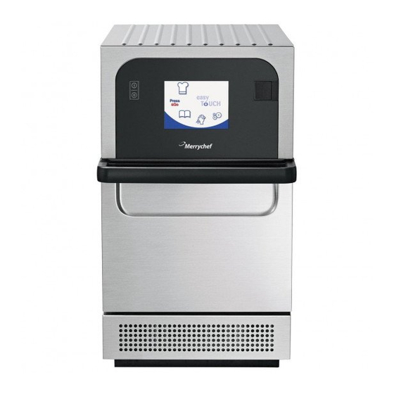
- Page 1 Microwave Combination Oven Read instructions before use Merrychef eikon e2s Service and Repair Manual CE – Original, GBR Part Number 32Z3935...
-
Page 3: Table Of Contents
Contents Contents General information EC Declaration of Conformity Environmental protection Important Information Identifying your microwave combination oven Structure of technical documentation About this Service and Repair Manual Design and function Design and function of the microwave combination oven Layout and function of the operating panel For your safety Basic safety code Intended use of your microwave combination oven... - Page 4 Contents Items required for cleaning Safe working when cleaning Cleaning procedures 7.5.1 Cool down procedure before cleaning 7.5.2 Cleaning instructions Technical data Technical data Dimensional drawings Diagnostics Checking the condition of your appliance Errors and diagnostics Fault finding Tests 10.1 Safe working when testing components 10.2 Requirements...
- Page 5 1 General information General information Purpose of this chapter This chapter shows you how to identify your microwave combination oven and provides guidance on using this manual. Contents This chapter contains the following topics: Page EC Declaration of Conformity Environmental protection Important Information Identifying your microwave combination oven Structure of technical documentation...
-
Page 6: Ec Declaration Of Conformity
1 General information 1.1 EC Declaration of Conformity Manufacturer Authorised Representative (Brand Headquarters) Factory Manitowoc Foodservice UK Limited Manitowoc Foodservice UK Limited Ashbourne House, The Guildway, Provincial Park, Nether Lane, Old Portsmouth Road Ecclesfield Guildford GU3 1LR Sheffield S35 9ZX... -
Page 7: Environmental Protection
Vice President Products: Merrychef (on behalf of the Authorised Representative) Quality and environmental management Manitowoc Foodservice UK Limited (Sheffield) employs a quality management system in accordance with EN ISO 9001:2008 and a certified environmental management system in accordance with EN ISO 14001. -
Page 8: Identifying Your Microwave Combination Oven
1 General information 1.4 Identifying your microwave combination oven Position of nameplate The nameplate is located on the rear of your microwave combination oven. 1 Model number eikon e2s 2 Elements of the item Label Meaning number Model Power output 2200W convection 2200W / 1300W... -
Page 9: Structure Of Technical Documentation
1 General information 1.5 Structure of technical documentation Contents The technical documentation for the microwave combination oven includes the following documents: Installation and Operating Manual Service and Repair Manual (this document) 1.6 About this Service and Repair Manual Purpose This Service and Repair Manual is intended for all people who work with the microwave combination oven, and provides them with the necessary information for carrying out servicing and repair work... - Page 10 1 General information Chapter/section Purpose Cleaning procedures Explains the principles of the cleaning methods Contains the cleaning instructions Describes the cleaning chemicals and how to prepare them for use Contains the instructions for working procedures during cleaning ...
-
Page 11: Design And Function
2 Design and function Design and function Purpose of this chapter This chapter describes the design and construction of the microwave combination oven and explains its functions. Contents This chapter contains the following topics: Page Design and function of the microwave combination oven Layout and function of the operating panel eikon e2s Service and Repair Manual CE... -
Page 12: Design And Function Of The Microwave Combination Oven
2 Design and function 2.1 Design and function of the microwave combination oven Parts and their function Item Name Function ON/OFF appliance switch Used to turn the microwave combination oven on and off. Turning this switch off does not isolate the appliance from the electricity supply. -
Page 13: Layout And Function Of The Operating Panel
2 Design and function Item Name Function Door seals The door seals ensure a tight seal around the door. Always keep them clean and check regularly for signs of damage. At the first sign of wear have them replaced by a Merrychef approved service agent. See 'Cleaning procedures' on page 58. -
Page 14: For Your Safety
3 For your safety For your safety Purpose of this chapter This chapter provides you with all the information you need in order to use the microwave combination oven safely without putting yourself or others at risk. This is a particularly important chapter that you must read through carefully. Contents This chapter contains the following topics: Page... -
Page 15: Basic Safety Code
3 For your safety 3.1 Basic safety code Object of this safety code This safety code aims to ensure that all persons who use the microwave combination oven have a thorough knowledge of the hazards and safety precautions, and that they follow the warning notices given in the user manual and on the appliance. - Page 16 3 For your safety Restrictions on use Only use utensils that are suitable for use in microwave combination ovens. See 'Procedure for preparing the appliance for use'. Do not use corrosive chemicals or vapors in this appliance. This type of oven is specifically designed to heat, cook or toast food.
- Page 17 3 For your safety The contents of feeding bottles and baby food jars must be stirred or shaken and the temperature checked before consumption, in order to avoid burns. Items should be unwrapped when using convection and combination func- tions.
- Page 18 3 For your safety Never tamper with the control panel, door, seals, or any other part of the appliance. Never hang dish towels or cloths on any part of the appliance. If the door or door seal is damaged, the appliance must not be operated until it has been repaired by a competent person.
- Page 19 3 For your safety More on this ... Related topics Summary of hazards Hazards and safety precautions during cleaning Hazards and safety precautions when moving the appliance Hazards and safety precautions when setting up the appliance ...
- Page 20 3 For your safety IMPORTANT This manual provides technical guidance for technicians who have successfully undertaken a recognized product familiarization and training course run by Merrychef to carry out ser- vice/repair tasks to the appliance/s shown on the front cover of this manual which must not be used for any other make or model of appliance.
- Page 21 3 For your safety IMPORTANT To Service Technicians: Precautions to be observed before and during servicing to avoid possible exposure to exces- sive microwave energy. Do not operate or allow the oven to be operated with the door open. Make the following safety checks on all ovens to be serviced before activating the magnetron or other microwave source, and make repairs as necessary: Interlock operation.
-
Page 22: Intended Use Of Your Microwave Combination Oven
3 For your safety 3.2 Intended use of your microwave combination oven Intended use of your microwave combination oven The microwave combination oven must only be used for the purposes specified below: The microwave combination oven is designed and built solely for cooking different foodstuffs in containers approved by the manufacturer. -
Page 23: Warning Signs On Your Microwave Combination Oven
3 For your safety 3.3 Warning signs on your microwave combination oven Warning and safety signs Mandatory warning signs The following warning signs / notices must be attached to the microwave combination oven and optional accessories in the area indicated so as to be easily visible at all times. eikon e2s Service and Repair Manual CE... - Page 24 3 For your safety Area Warning sign Description Microwaves warning There is a risk of external and internal burns of body parts following exposure to microwave energy. Electric shock warning There is a risk of electric shock if the appliance is serviced without discon- necting the electrical supply.
-
Page 25: Summary Of Hazards
3 For your safety 3.4 Summary of hazards General rules for dealing with hazards and safety precautions The microwave combination oven is designed to protect the user from all hazards that can reasonably be avoided by design measures. The actual purpose of the microwave combination oven, however, means that there are still residual risks;... - Page 26 3 For your safety Hot liquids Foodstuffs are cooked in the microwave combination oven. These foodstuffs may also be liquid, or liquefy during cooking. This poses a risk of scalding from hot liquids, which may be spilled if not handled properly.
-
Page 27: Hazards And Safety Precautions When Moving The Appliance
3 For your safety 3.5 Hazards and safety precautions when moving the appliance Safety hazard: moving heavy weights Danger Where or in what situations does the Preventive action hazard arise? Risk of injury from over- When moving the appliance onto and off Use a forklift truck or pallet truck stressing your body the moving equipment... -
Page 28: Hazards And Safety Precautions When Setting Up The Appliance
3 For your safety 3.6 Hazards and safety precautions when setting up the appliance Safety hazard: moving heavy weights Danger Where or in what situations does the Preventive action hazard arise? Risk of injury from over- When moving the appliance Use a forklift truck or pallet truck to stressing your body place the appliance in the installation... -
Page 29: Hazards And Safety Precautions During Installing
3 For your safety 3.7 Hazards and safety precautions during installing Safety hazard: electrical power Danger Where or in what situations does the Preventive action hazard arise? Risk of electric shock from Under covers Work on the electrical system must only live parts be performed by qualified electricians ... -
Page 30: Hazards And Safety Precautions When Preparing Appliance For Use
3 For your safety 3.8 Hazards and safety precautions when preparing appliance for Safety hazard: electrical power Danger Where or in what situations does the Preventive action hazard arise? Risk of electric shock from Work on the electrical system must only Under covers live parts ... -
Page 31: Hazards And Safety Precautions During Cleaning
3 For your safety 3.9 Hazards and safety precautions during cleaning Safety hazard: cleaning chemicals Danger Where or in what situations does the Preventive action hazard arise? Risk of chemical burns or For all cleaning actions Do not let cleaning chemicals come irritation to skin, eyes and into contact with your skin or eyes respiratory system from... - Page 32 3 For your safety Safety hazard: moving appliances supported on a wheeled base Danger Where or in what situations does the Preventive action hazard arise? All specified hazards While appliances are being moved on a When moving the microwave combina- wheeled platform tion oven, take care not to wheel over the electrical supply cables...
-
Page 33: Hazards And Safety Precautions During Servicing And Repair
3 For your safety 3.10 Hazards and safety precautions during servicing and repair Safety hazard: heat Danger Where or in what situations does the Preventive action hazard arise? A risk of burns from hot Inside the entire cavity, including all parts Before starting cleaning tasks, wait surfaces that are or were inside during cooking,... - Page 34 3 For your safety Safety hazard: moving heavy weights Danger Where or in what situations does the Preventive action hazard arise? Risk of injury from over- When moving the appliance Use a forklift truck or pallet truck to stressing your body place the appliance in the installation position or to move it to a new position ...
-
Page 35: Hazards And Safety Precautions When Taking The Appliance Out Of Service
3 For your safety 3.11 Hazards and safety precautions when taking the appliance out of service Safety hazard: electrical power Danger Where or in what situations does the Preventive action hazard arise? Risk of electric shock from Work on the electrical system must only Under covers live parts ... -
Page 36: Safety Devices
3 For your safety 3.12 Safety devices Meaning The microwave combination oven has a number of safety devices to protect the user from hazards. It is absolutely essential that all safety devices are fitted and in working order when operating the appliance. Position and function Item Safety device... - Page 37 3 For your safety Item Safety device Function Check Action: Disconnection device Installed by the customer close to the appliance; easily visible Trip the disconnection device (no picture, and accessible, 1- or 3-pole installed by action, minimum contact separa- customer) tion 3 mm.
-
Page 38: Requirements To Be Met By Personnel And Working Positions
3 For your safety 3.13 Requirements to be met by personnel and working positions Requirements to be met by operating personnel Personnel Qualifications Tasks Service technician Is an authorized service agent All servicing and repair work Has relevant technical training ... -
Page 39: Personal Protective Equipment
3 For your safety 3.14 Personal protective equipment Moving and setting up the appliance Activity Materials used Personal protective equipment Conveying within the establishment Suitable lifting gear Protective gloves Setting up the appliance on a work Forklift truck or pallet Safety boots surface, stand or in a stacking kit... - Page 40 3 For your safety Cleaning Activity Materials used Personal protective equipment Cleaning the cavity by hand Cleaning chemicals Items of protection equipment, de- approved by the manu- pending on cleaning chemical being Handling spray bottles facturer used: ...
-
Page 41: Setting Up The Appliance
4 Setting up the appliance Setting up the appliance Purpose of this chapter This chapter provides information on how to set up your appliance. This chapter is intended for the user and for a qualified member of staff from an authorized service company. -
Page 42: Safe Working When Setting Up The Appliance
4 Setting up the appliance 4.1 Safe working when setting up the appliance For your safety Before starting work, familiarize yourself with the hazards described in 'Hazards and safety precautions when setting up the appliance' on page 27. Eligibility of personnel for setting up the appliance Personnel eligible for setting up the appliance: ... -
Page 43: Requirements For The Installation Location
4 Setting up the appliance 4.2 Requirements for the installation location Meaning This section contains information to help you choose a suitable installation location for the microwave combination oven. Inspect the intended installation location carefully to ensure it is suitable before taking the appliance there and starting the installation. -
Page 44: Mounting The Appliance On A Work Surface
4 Setting up the appliance Minimum space required The following diagram and table show the space required for the appliance for different installation and operating situations. They also show the minimum horizontal distances from adjacent walls and sur- faces. The safety clearance on the top must always be complied with. Meaning Space required Safety clearance from the top... -
Page 45: Installation
5 Installation Installation Purpose of this chapter This chapter explains how to connect your microwave combination oven to the electrical supply. Contents This chapter contains the following topics: Page Safe working during electrical installation Planning the electrical installation Electrical installation requirements eikon e2s Service and Repair Manual CE... -
Page 46: Safe Working During Electrical Installation
5 Installation 5.1 Safe working during electrical installation For your safety Before starting work, familiarize yourself with the hazards described in 'Hazards and safety precautions during installation' on page 28. Eligibility of personnel for the electrical installation Only electricians qualified under the terms of EN 50110-1 and from an authorized service company are permitted to perform work on electrical equipment. -
Page 47: Planning The Electrical Installation
5 Installation 5.2 Planning the electrical installation Meaning It is crucial to the safe and reliable operation of the appliance that the electrical system is installed carefully and correctly. All the rules and regulations listed here, and the described procedure, must be strictly followed. -
Page 48: Electrical Installation Requirements
5 Installation Properties of the residual-current device The residual-current device (RCD) must have the following properties: Filter for filtering out RF currents “Time delayed" trip characteristic for RCD devices with trip threshold >30mA: prevents RCD being tripped by charging currents of capacitors and parasitic capacitances when appliance is switched on. ... - Page 49 5 Installation Phase loading diagram Explanation to phase loading diagram Phase Loading Loading per phase is not equal. Therefore it is recommended to connect other electrical equipment to L3+N. eikon e2s Service and Repair Manual CE...
-
Page 50: Preparing The Appliance For Use
6 Preparing the appliance for use Preparing the appliance for use Purpose of this chapter This chapter shows you how to put the microwave combination oven into operation and how to cook. Contents This chapter contains the following topics: Page Safe working when preparing the appliance for use Procedure for preparing the appliance for use Start page... - Page 51 6 Preparing the appliance for use 6.1 Safe working when preparing the appliance for use For your safety when preparing the appliance for use Before starting work, make sure that you are familiar with the hazards described under 'Hazards and safety precautions when preparing appliance for use' on page 29 and in the chapter 'For your safety' in the user manual.
- Page 52 6 Preparing the appliance for use Hot steam / vapour Risk of scalding from hot steam and vapour When opening the door, always be cautious of escaping hot steam and vapour which can cause scalding to face, hands, feet and legs. ...
- Page 53 6 Preparing the appliance for use 6.2 Procedure for preparing the appliance for use Checks prior to preparing the appliance for use Before preparing the microwave combination oven for use use the checklists below to make sure that all important requirements are met. The appliance must not be put into operation until all the specified requirements are met.
- Page 54 6 Preparing the appliance for use Start up Make all the relevant safety checks and ensure the appliance is clean and empty. Then switch the appliance ON. ® The easyTouch screen illuminates with the display briefly showing the serial number and appliance data. If required, to keep the data on the screen, lightly tap the screen once to freeze the display.
- Page 55 6 Preparing the appliance for use 6.3 Start page Appearance The buttons and what they do Function Button Meaning Development Mode 'Development Mode' enables multistage cooking profiles to be developed, then stored under a name and symbol for reuse. Press&Go 'Press&Go' allows quick access to use the cooking profiles that are already stored.
-
Page 56: The Keyboard Screen
6 Preparing the appliance for use 6.4 The keyboard screen Appearance The buttons and their functions Button Meaning Function Keyboard screen Keyboard screen is used to enter an authorised password to enter data for programs and may restrict operator access to some functions. -
Page 57: Using A Usb Stick
6 Preparing the appliance for use 6.5 Using a USB stick Purpose of the USB cover The USB cover protects the USB port so that no water vapour can get into the control electronics during cooking or cleaning. During cooking and cleaning, there must not be a USB stick inserted and the USB port must be closed by the cover. - Page 58 6 Preparing the appliance for use Switch the appliance ON. The files automatically download from the USB memory stick showing the progress and confirmation screens for the update. On completion the appliance displays the start up screen. Then the thermometer symbol is displayed. Remove the USB memory stick and keep it in a safe place.
-
Page 59: Cleaning Procedures
7 Cleaning procedures Cleaning procedures Purpose of this chapter This chapter summarizes the cleaning methods, the cleaning chemicals and how to handle them and the cleaning instructions. It explains the correct procedure to follow when cleaning the microwave combi- nation oven. Contents This chapter contains the following topics: Page... -
Page 60: Daily Cleaning Tasks
7 Cleaning procedures 7.1 Daily cleaning tasks What must be cleaned? Procedure Cleaning chemicals Cavity Clean by hand with a soft cloth / Cleaning and protective chemicals paper towel approved by the manufacturer Outside of appliance Clean by hand with a soft cloth Common household stainless steel cleaner or hard surface cleaner ... -
Page 61: Items Required For Cleaning
7 Cleaning procedures 7.3 Items required for cleaning Items required for cleaning Merrychef cleaning chemical Merrychef protective chemical Protective rubber gloves Non-abrasive nylon scrub pad Cleaning towel and cloths Eye protection Heat proof gloves (optional) ... -
Page 62: Safe Working When Cleaning
7 Cleaning procedures 7.4 Safe working when cleaning Your safety and the safety of your staff Before your personnel start working with the microwave combination oven for the first time, familiarize yourself with the information contained in the chapter 'For your safety' on page 13 and make relevant safety arrangements. - Page 63 7 Cleaning procedures Spraying water into a hot cavity Risk of scalding from hot steam If water is sprayed into the hot cavity, steam will be produced that may scald. Before starting cleaning tasks, wait until the cavity has cooled to below 50°C / 122°F or use the 'Cool Down' function to cool the cavity.
-
Page 64: Cleaning Procedures
7 Cleaning procedures 7.5 Cleaning procedures Cleaning the microwave combination oven This section explains how to clean your microwave combination oven. Contents This section contains the following topics: Page Cool down procedure before cleaning Cleaning instructions eikon e2s Service and Repair Manual CE... -
Page 65: Cool Down Procedure Before Cleaning
7 Cleaning procedures 7.5.1 Cool down procedure before cleaning For your safety when cleaning Before starting cleaning work, it is essential that you familiarize yourself with the rules and hazard warnings specified in 'Safe working when cleaning' on page 61, and follow the instructions given there. Purpose With the optional 'cool down' function you can cool down the cavity quickly for cleaning your microwave combination oven sooner. - Page 66 7 Cleaning procedures Taking all necessary precautions place a suitable tray of ice cubes into the hot cavity. This speeds up the cooling process. Press the green tick to continue. The cooling progress is displayed and takes approximately 20 minutes. To reduce the cool down time to about 20 minutes leave the appliance door open slightly during the cooling process.
-
Page 67: Cleaning Instructions
7 Cleaning procedures 7.5.2 Cleaning instructions For your safety when cleaning Before starting cleaning work, it is essential that you familiarize yourself with the rules and hazard warnings specified in 'Safe working when cleaning' on page 61, and follow the instructions given there. Requirements for cleaning the appliance ... - Page 68 7 Cleaning procedures For difficult areas, leave to soak for 10 minutes with the appliance door open. Use a non-abrasive nylon scrub pad/sponge to clean all surfaces of the cavity including the roof and the inside surface of the appliance door. NOTICE: Do not scrub the door seal or use metallic scourers.
- Page 69 7 Cleaning procedures Applying the protective chemical, cleaning the air filter After completing the cleaning procedures press the green tick to confirm that the cavity has been cleaned. You can then apply a protective chemical to make cleaning easier the next day (optional). Spray protective chemical approved by Merrychef onto a clean sponge.
- Page 70 7 Cleaning procedures Replace all mobile parts into the cavity that had been removed for cleaning. Close the appliance door. Press the green tick to confirm application of the protective chemical. A prompt appears asking to clean the air filter. Tilt the faceplate below the appliance door downwards.
- Page 71 7 Cleaning procedures Remove the air filter. Clean the air filter with a damp cloth. Replace the air filter and tilt the faceplate in its original position. Clean the oven exterior with a damp cloth. Press the green tick to confirm cleaning of the air filter. The oven switches off.
-
Page 72: Technical Data
8 Technical data Technical data Purpose of this chapter This chapter contains the technical data for your microwave combination oven. Contents This chapter contains the following topics: Page Technical data Dimensional drawings eikon e2s Service and Repair Manual CE... -
Page 73: Technical Data
8 Technical data 8.1 Technical data Dimensions and weights Width Including packaging [in] 21.1 [mm] Appliance without packaging [in] 14.0 [mm] Height Including packaging [in] 33.5 [mm] Appliance ("Classic" exterior) without packaging [in] 24.4 [mm] Appliance ("Trend" exterior) without packaging [in] 25.4 [mm]... - Page 74 8 Technical data Electrical connected load ratings – Standard Power version Electrical supply 1N~ 220-230V 1N~ 220-230V 1N~ 220V 60Hz 50Hz 50Hz Connections used L + N + E L + N + E L + N + E Arrangement Single Phase Single Phase Single Phase...
-
Page 75: Dimensional Drawings
8 Technical data 8.2 Dimensional drawings Front view (door closed) Cavity dimensions (door closed) View from the top (door closed) View from the right hand side (door open) eikon e2s Service and Repair Manual CE... -
Page 76: Diagnostics
9 Diagnostics Diagnostics Purpose of this chapter This chapter contains information on checking various functions of your microwave combination. Contents This chapter contains the following topics: Page Checking the condition of your appliance Errors and diagnostics Fault finding eikon e2s Service and Repair Manual CE... -
Page 77: Checking The Condition Of Your Appliance
9 Diagnostics 9.1 Checking the condition of your appliance Servicing procedure: overview Disconnect/isolate the appliance from the power supply. Check the appliance is correctly installed as described in the “Installation” section of this manual. Visually check the cleanliness/condition of the power supply/cable/gland, casing, cavity and door of the appliance for signs of wear, damage, distortion etc. - Page 78 9 Diagnostics Enter the service password, for example, "SERVICE" on the keypad. Select OK to display the Error Log, service information and test options. Touchscreen calibration Apply continuous light pressure to the screen while switching the appliance on. Continue to hold until the progress bar has completed. Using a non-abrasive pointer, such as a ball point pen, accurately press the centre of each crosshair displayed on the screen.
- Page 79 9 Diagnostics If the crosshairs turn green three times consecutively the cali- bration process is completed successfully. Once calibrated the screen will display information about the appliance. Functions of the Service Mode Check the "Error Log" for details of any logged appliance errors. Check the "Oven Counters"...
- Page 80 9 Diagnostics Perform the tests of your microwave combination oven as de- scribed. See “Tests” section of this manual. If required refer to the “Replacing components” section for any repairs needed before continuing with the tests. Follow the procedures under “Commissioning the appliance” before commissioning your appliance for use.
-
Page 81: Errors And Diagnostics
9 Diagnostics 9.2 Errors and diagnostics Error messages A description of the type of error is shown. Check for a number following ‘ERROR:’ and refer to the error codes (“Fault Finding” section of this manual) for more details. The serial number of the oven, model, UI (QTS) version and SRB version information are also displayed below. - Page 82 9 Diagnostics Open the cover of the USB port and insert the USB memory stick into the slot. NOTE: The USB memory stick may take several seconds to load before the screen will respond. Select ‘Upload Files’ on the USB screen. Select ‘Error Log’...
- Page 83 9 Diagnostics Select the green tick to copy the error log to the USB memory stick. The upload progress is shown followed by the upload status. Select backspace 3 times to return to the main menu. Remove the USB memory stick. Error Log Enter Service Mode and select ‘Error Log’...
- Page 84 9 Diagnostics Cooking Profile counter Select ‘Oven Counters’ to display the oven component usage and ambient controls area temperature. Details include the number of screen touches, filter cycles, door cycles, total oven power, magnetron and heater element power on time and the ambient controls area temperature in the cabinet. Select backspace to return to the Service Menu.
- Page 85 9 Diagnostics Remove the air filter at the front of the oven. The colour of the air filter symbol on the display should change from green to red indicating that the magnetic reed switch circuit for the air filter is operating correctly. Replace the air filter and the colour should change back to green.
- Page 86 9 Diagnostics Place a microwave safe container of water into the cavity, and close the oven door. Select a magnetron to test the current draw at maximum output, this will time-out after 30 seconds. Dual magnetron model (2000W e2s variant): Test the magnetrons individually and together.
- Page 87 9 Diagnostics Select one and then the second magnetron (2000W e2s variant only) and check if they are operating correctly. eikon e2s Service and Repair Manual CE...
-
Page 88: Fault Finding
9 Diagnostics 9.3 Fault finding Hardware control components Operations communication: The oven has 2 main parts being the QTS assembly (Keyboard, Screen, Logic) and the SRB (Smart Relay Board to switch and monitor the required operation). The QTS is the master of the oven and instructs the SRB what to do, in turn the SRB communicates information on the operation back to the QTS. - Page 89 9 Diagnostics Error Code List Error Error Description Trigger Possible Causes System Code Condition Response E 101 Magnetron Detects a magne- The current Failure of com- Display error failed to tron is not working measured by the ponent/s in the message until energise correctly...
- Page 90 9 Diagnostics E 108 QTS PM Wrong PM found / The QTS or SRB The PM has been Display error error no PM found either has an changed and is message until incorrect PM incorrect. The PM system is power (Personality Mod- has been re- cycled.
- Page 91 9 Diagnostics Screen Touch screen Continual pres- Damaged touch Display error frozen inoperable sure of the touch screen / touch message until screen screen depress for touch screen more than 15 press released seconds. Error code for recommission test messages 89 Cooling test fail 90 Convection test fail 92 Heater test fail...
-
Page 92: Tests
10 Tests 10 Tests Purpose of this chapter This chapter contains information on testing single components of your microwave combination oven. Contents This chapter contains the following topics: Page Safe working when testing components Requirements Testing selected components (casing mounted) High voltage components (casing removed) Mains voltage components (casing removed) eikon e2s Service and Repair Manual CE... -
Page 93: Safe Working When Testing Components
10 Tests 10.1 Safe working when testing components For your safety when testing oven components Before starting oven tests, it is essential that you familiarize yourself with the rules and hazard warnings specified and follow the instructions given there. Eligibility of personnel for testing oven components Only qualified personnel from an authorized service company are permitted to test components of the microwave combination oven. - Page 94 10 Tests Hot surfaces Risk of burns from high temperatures inside the cavity and on the inside of the appliance door You may get burnt if you touch any of the interior parts of the cooking chamber, the inside of the appliance door or any parts that were inside the oven during cooking.
-
Page 95: Requirements
10 Tests 10.2 Requirements Equipment required for testing the appliance Portable Appliance Tester (P.A.T.) Digital Multi-Meter (D.M.M.) Megger / similar 500 V d. c. resistance meter Microwave detection / leakage meter Temperature reader Continuity meter ... - Page 96 10 Tests Earth/Insulation Test Check that the following requirements have been met: The appliance has been disconnected from the power supply and protective measures have been taken to ensure the power cannot be switched on again. Connect the mains lead from the appliance to a Portable Appli- ance Tester.
- Page 97 10 Tests Microwave Power Test: Measuring the microwave power output of the magnetron(s) Check that the following requirements have been met: The appliance is cool. NOTE: The power output is established under IEC 705 standard method which is only workable in laboratory controlled conditions.
- Page 98 10 Tests When the countdown has finished, remove the container from the cavity. Immediately stir with a plastic implement and measure the water temperature. Calculate the temperature rise of the water (end temperature minus the start temperature). The temperature rise should be 14.3°C (25.7°F) ±10% for the 1000W (1 magnetron) variant.
- Page 99 10 Tests Add 275 ml of cold water into a 600 ml microwave safe container. Place the 600 ml container in the centre of the cavity and close the door. Enter Service Mode on the screen and select ‘Microwave leakage test’...
- Page 100 10 Tests When the magnetron circuit stops after 30 seconds, change the water and re-select the test to continue. Select the red ‘X’ on the display to stop the test at any time. Readings must be below 5 mW/cm². CAUTION: If a level greater than 5 mW/cm²...
- Page 101 10 Tests Temperature Control test: measuring the cavity temperature NOTE: Re-calibrating the temperature sensor / thermocouple with the SRB is normally only required when the thermocouple has been replaced or the appliance is under or over cooking. Place the probe of a temperature reader onto a heat sink or a metal plate in the centre of the oven cavity and close the door.
- Page 102 10 Tests If the temperature reading is different to the maximum set point, scroll up to select TEMP. COMP. (Temperature Compensation) and enter the password. Enter the figure from the temperature reader on the keypad and select OK to calibrate the SRB to the temperature sensor (ther- mocouple).
- Page 103 10 Tests If the temperature reading is unstable: Disconnect and isolate the appliance from the electricity supply. Take protective measures to ensure the power cannot be switched on again. Allow the appliance to cool down. Remove the side and top panels of the casing. Check the cavity temperature sensor wire and connections.
-
Page 104: High Voltage Components (Casing Removed)
10 Tests 10.4 High voltage components (casing removed) High Voltage Transformer test Ensure the following requirements have been met before starting the test: The appliance has been disconnected from the power supply and protective measures have been taken to ensure the power cannot be switched on again. ... - Page 105 10 Tests High Voltage Diode test Ensure the following requirements have been met before starting the test: The appliance has been disconnected from the power supply and protective measures have been taken to ensure the power cannot be switched on again. ...
- Page 106 10 Tests Connect the DMM to one terminal and the metal outer case of the high voltage capacitor. The test is passed if the DMM display reads "open circuit". Repeat the test for the other terminal and the metal outer case. Using a megger, test the insulation resistance between both terminals and the metal outer case of the high voltage capacitor.
-
Page 107: Mains Voltage Components (Casing Removed)
10 Tests 10.5 Mains voltage components (casing removed) Convection fan: motor The convection fan motor is a 3-phase AC motor having a maximum speed of 7200 rpm controlled by a motor speed controller. The windings are thermally protected and in the event of a thermal fault a trip inside the motor will operate and shut down the motor speed controller. -
Page 108: Oven Firmware
11 Oven firmware 11 Oven firmware Purpose of this chapter This chapter informs about the correct procedure to check and update the firmware of the appliance. 11.1 Firmware Updates Overview Switch on the oven. Tap the top right hand corner of the screen. Enter the correct password (the default password is "MANAGER") and select the green check mark. - Page 109 11 Oven firmware Select one of the USB options: ‘Firmware’ for QTS & SRB updates ‘Recipes’ for icons. Install the SRB update first, the QTS update second and any icons third. Alternatively, if you have the Autoupd.ate file present on the USB be aware that all files of your USB will be loaded and overwrite the existing files.
- Page 110 11 Oven firmware Requirement: To format a USB memory stick, place it in a PC USB slot, select 'Computer' and right click on the USB memory stick symbol. Select 'Format' and select FAT (Do NOT select FAT 32). NOTE: This will erase all data on the USB memory stick. Procedure: With the oven switched OFF, open the cover of the USB port and insert the USB memory stick into the slot.
- Page 111 11 Oven firmware Select the USB symbol. Once the USB memory stick has stopped flashing, select the 'Firmware' USB symbol. The current QTS (Quick Touch Screen) and SRB (Smart Relay Board) firmware versions are displayed at the top left of the screen.
- Page 112 11 Oven firmware SRB firmware update Select the ‘SRB’ file with the correct file version number. NOTE: A tinted band over a file name indicates the file is not valid for your oven. Check if the file information shown is correct before selecting OK. If not select ‘X’...
- Page 113 11 Oven firmware The SRB file is checked and the download progress from the USB is displayed followed by the update status and confirmation screens. NOTE: Wait until all files have been loaded. Do not touch the oven until the end of the downloading process. When the download process is complete press the return arrow and select the QTS file and repeat.
- Page 114 11 Oven firmware QTS firmware update Select the ‘QTS’ file with the correct file version number. NOTE: A tinted band over a file name indicates the file is not valid for that appliance. Check if the file information shown is correct before selecting OK. If not, select ‘X’...
- Page 115 11 Oven firmware Check if the screen shows the correct QTS version. If not, repeat the process using the correct file. Remove the USB memory stick and keep it in a safe place. Download procedure NOTICE Do not remove the USB memory stick during the download sequence as this could corrupt the USB data.
- Page 116 11 Oven firmware Tap the top right of the screen to bypass the preheat stage. Enter the password and select OK to display the settings menu. Select the USB symbol. Select the 'Firmware' USB symbol. eikon e2s Service and Repair Manual CE...
- Page 117 11 Oven firmware Select the ‘QTS’ file with the correct file version number. NOTE: A tinted band over a file name indicates the file is not valid for that appliance. Check the file information shown is correct before selecting the green check mark.
- Page 118 11 Oven firmware The CBR file is checked and the download progress from the USB memory stick is displayed followed by the update status and confirmation screens. eikon e2s Service and Repair Manual CE...
- Page 119 11 Oven firmware The QTS, SRB and Application Icon files then download auto- matically showing the progress, status and reboot confirmation screens for each file update. eikon e2s Service and Repair Manual CE...
- Page 120 11 Oven firmware On completion the start up screen is displayed showing the updated firmware versions followed by the pre-heat temperature screen. Confirming the firmware update After an update of the appliance firmware certain files are copied back to the USB memory stick. You can check if the file transfer was successful with the following procedure: Load the files from the USB memory stick to a computer.
- Page 121 11 Oven firmware PM (Personality Module) replacement – firmware update NOTE: The Personality Module on the SRB contains the firmware. The Personality Module on the QTS contains the firmware, serial number of your appliance, tem- perature calibration, cooking profiles, application icons and the recipe images. With a new Personality Module fitted and casing refitted, switch on the appliance and tap the screen to hold and check the QTS and SRB versions are the latest release.
- Page 122 11 Oven firmware Open the cover to the USB port and insert the USB memory stick into the slot. NOTE: The USB memory stick may take several seconds to load before the screen will respond. Once the USB memory stick has stopped flashing, select the required "USB Recipes"...
- Page 123 11 Oven firmware Check the file information shown is correct before selecting OK. If not, select ‘X’ and locate the correct file. When completed, select menu file to load the cooking profiles. Once the cooking profiles are loaded the appliance restarts. Enter the date and time settings.
-
Page 124: Replacing Components
12 Replacing components 12 Replacing components Purpose of this chapter This chapter contains information on how to remove and fit components of the oven. Contents This chapter contains the following topics: Page Safe working when replacing appliance parts Overview Removing / fitting the casing Removing / fitting the door assembly Replacing a magnetron Replacing the cooling fan... - Page 125 12 Replacing components 12.1 Safe working when replacing appliance parts For your safety when replacing appliance parts Before starting service / repair work, it is essential that you familiarize yourself with the rules and hazard warnings specified and follow the instructions given there. Eligibility of personnel for removal / fitting of appliance parts Only qualified personnel from an authorized service company are permitted to remove and fit compo- nents of the microwave combination oven.
- Page 126 12 Replacing components Hot surfaces Risk of burns from high temperatures inside the cavity and on the inside of the appliance door You may get burnt if you touch any of the interior parts of the cooking chamber, the inside of the appliance door or any parts that were inside the oven during cooking.
- Page 127 12 Replacing components 12.2 Overview View: left hand side eikon e2s Service and Repair Manual CE...
- Page 128 12 Replacing components View: right hand side eikon e2s Service and Repair Manual CE...
- Page 129 12 Replacing components View: rear side eikon e2s Service and Repair Manual CE...
- Page 130 12 Replacing components Component List Item Name Function Front panel The front panel houses the touchscreen and the QTS assembly. Door handle Open the oven door using the door handle. Never use the door handle to lift the appliance. Door cover panel The door cover panel can be detached for accessing the door hinge assembly.
- Page 131 12 Replacing components Item Name Function Cavity thermostat (cavity overheat stat) The thermostat continuously measures the temper- ature in the cavity and prevents it from overheating. Cavity temperature sensor wire (thermocouple) The sensor wire extends between the thermostat entering the cavity and the interior of the cavity.
-
Page 132: Removing / Fitting The Casing
12 Replacing components 12.3 Removing / fitting the casing Tools required M5.5 hex socket wrench Requirements Check that the following requirements have been met: The appliance has been disconnected from the power supply and protective measures have been taken to ensure the power cannot be switched on again. ... - Page 133 12 Replacing components Remove top panel first. Unfasten three M5.5 hex head flange bolts at the back panel of the appliance attaching the top panel to the back panel. Slide the top panel towards the back of the appliance and remove Removing the side panels: Unfasten six M5.5 hex head flange bolts (three per side) at the back panel of the appliance attaching each side panel to the back...
- Page 134 12 Replacing components Fitting the panels of the casing Follow the steps in the reverse order to fit the panels of the casing. eikon e2s Service and Repair Manual CE...
-
Page 135: Removing / Fitting The Door Assembly
12 Replacing components 12.4 Removing / fitting the door assembly Component Tools required Two metal pins (length: 10 mm / 0.4 in) M5.5 hex socket wrench M8 hex socket wrench Requirements Check that the following requirements have been met: The appliance has been disconnected from the power supply and protective measures have been taken to ensure the power cannot be switched on again. - Page 136 12 Replacing components Tilt the oven door to an angle of approx. 30° relative to the ground. Remove the door assembly from the oven performing a rotational movement of lifting the door up and pulling it away from the casing. Unfasten two M5.5 hex head flange bolts next to the door hinges to remove the cover panel from the door frame.
- Page 137 12 Replacing components Turn the door assembly around. Slide the cover panel away from the door handle to remove it from the door frame. Remove the two thermal insulation pads located between the springs attached to the door hinges and the door handle. Unfasten two M8 hex cap screws on each side.
- Page 138 12 Replacing components Remove all insulation pads/mats from the door. Unfasten two M8 hex cap screws. Remove/replace the door hinge units if required. eikon e2s Service and Repair Manual CE...
- Page 139 12 Replacing components Fitting the components of the door assembly Follow the steps in the reverse order to reassemble the compo- nents of the oven door and to fit it to the oven. NOTE: Carefully refit the insulation pads/mats to their original positions. eikon e2s Service and Repair Manual CE...
-
Page 140: Replacing A Magnetron
12 Replacing components 12.5 Replacing a magnetron Component The magnetron(s) is/are located on top of the cavity and is/are fixed to the cooling duct and the cavity roof. The 2000W e2s variant comprises two magnetrons located on the left and right hand sides of the cooling duct. The cooling duct covers one side of the magnetron where the magnetron is attached to the cavity roof with two screws. - Page 141 12 Replacing components The outlet of the cooling duct carries heat to the back of the oven and is covered by a grille. The outlet comprises a sheet metal frame containing holes corresponding to the positions of Pozidriv screws securing the cooling duct to the magnetron.
- Page 142 12 Replacing components Preparing a spare magnetron The spare magnetron comes with four pressed bolts. Remove the bolts before fitting the magnetron to the oven. NOTE: The bolts can be removed by knocking them out of the tabs with a hammer.
- Page 143 12 Replacing components Unfasten one Pozidriv screw on the left side of the cooling duct with a long PZ2 Pozidriv screwdriver using the corresponding access hole at the cooling duct (when looking at the back side of the oven). NOTE: The number of screws on the left side of the cooling duct depends on the number of magnetrons fitted.
- Page 144 12 Replacing components Unfasten four M8 hex cap screws to remove the magnetron. There is one pair of screws on each side of the magnetron. Disconnect any cables leading into the magnetron(s). Fitting a magnetron Follow the steps in the reverse order to fit a spare magnetron. Ensure nothing becomes trapped under the magnetron mounting points (e.
-
Page 145: Replacing The Cooling Fan
12 Replacing components 12.6 Replacing the cooling fan Component The cooling fan is located under the cavity and can be accessed by removing the convection fan motor speed controller. Tools required M7 hex socket wrench Requirements Check that the following requirements have been met: ... - Page 146 12 Replacing components Removing the cooling fan Unplug the electrical connection of the cooling fan on the right hand side of the appliance. Unfasten two M7 hex nuts each securing one arm of the sheet metal bracket which holds the cooling fan. Then turn the bracket clockwise.
-
Page 147: Replacing The Qts (Quick Touch Screen) Assembly
12 Replacing components 12.7 Replacing the QTS (Quick Touch Screen) assembly Component Top section (picture on the left): The QTS (Quick Touch Screen) board lies behind the easyToUCH screen and is attached to the front panel of the oven. Bottom section (picture on the left): The much larger SRB (System Relay Board) extends over the whole width of the oven and rests in a tilted position close to the front panel of the oven. - Page 148 12 Replacing components Removing the QTS assembly Disconnect all cables connecting the QTS assembly to the SRB. Remove the top front panel (including the touchscreen and QTS assembly) from the frame of the casing: Unfasten two M5.5 hex head flange bolts fixing the front panel to the sheet metal frame.
- Page 149 12 Replacing components 1) Slide the front panel upwards. 2) Then carefully pull the front panel away from the sheet metal frame. Double check that all cables connecting the QTS assembly to the SRB have been removed. eikon e2s Service and Repair Manual CE...
- Page 150 12 Replacing components Unfasten four M5.5 hex head flange bolts to remove the QTS assembly from the front panel. Lift out the QTS assembly. Remove the PM (Personality Module) from the QTS and place safely aside. NOTICE: Do not use tools to remove or refit the Personality Module. eikon e2s Service and Repair Manual CE...
- Page 151 12 Replacing components Fitting the QTS assembly Follow the steps in the reverse order to fit the QTS assembly. Reconnect all electric connections to the QTS board. Fit the PM removed from the old QTS to the new QTS. Reason: Replacement QTS / SRB units come WITHOUT Personality Modules as they store individual settings saved by the user.
-
Page 152: Replacing The Srb (Smart Relay Board)
12 Replacing components 12.8 Replacing the SRB (Smart Relay Board) Component Bottom section (picture on the left): The much larger SRB (System Relay Board) extends over the whole width of the oven and rests in a tilted position close to the front panel of the oven. - Page 153 12 Replacing components Remove the PM (Personality Module) from the SRB and place safely aside. NOTICE: Do not use tools to remove or refit the Personality Module. Fitting the SRB Follow the steps in the reverse order to fit the SRB. Reconnect all electric connections to the SRB.
-
Page 154: Replacing The Touchscreen Overlay
12 Replacing components 12.9 Replacing the touchscreen overlay Component Tools required M5.5 hex socket wrench Requirements Check that the following requirements have been met: The appliance has been disconnected from the power supply and protective measures have been taken to ensure the power cannot be switched on again. ... - Page 155 12 Replacing components Slide the touchscreen element to the left and detach it from the frame of the casing. NOTICE: Mind the cables attached to the QTS assembly. Fitting the touchscreen overlay Follow the steps in the reverse order to fit the touchscreen overlay. NOTICE: If the electric connections have not been restored properly this may lead to malfunction/damage of the oven.
-
Page 156: Adjusting The Door Microswitches / Interlocks
12 Replacing components 12.10 Adjusting the door microswitches / interlocks Component Adjust the microswitches after replacing old with new door hinges. Micro-switch alignment is NOT required if just refitting the same door. Tools required M7 hex socket wrench Requirements Check that the following requirements have been met: ... - Page 157 12 Replacing components Slacken the pivot screw using a M7 hex socket wrench. Release the adjusting screws and move the backplate until microswitch SW3 just activates. Then secure all screws. Open the appliance door to replace the green 2 mm spacers with red 4 mm spacers and close the door.
-
Page 158: Replacing The Stirrer Motor
12 Replacing components 12.11 Replacing the stirrer motor Component Tools required M5.5 hex socket wrench M7 hex socket wrench Pozidriv PZ1 screwdriver Requirements Check that the following requirements have been met: The appliance has been disconnected from the power supply and protective measures have been taken to ensure the power cannot be switched on again. - Page 159 12 Replacing components Removing the stirrer motor Unfasten two M5.5 hex head flange bolts to remove the jet/impinger plate from the roof of the cavity. NOTE: At the rear the jet/impinger plate rests in a bracket. Remove the jet/impinger plate from the cavity. Unfasten sixteen (16) M7 hex nuts.
- Page 160 12 Replacing components Remove the partition plate from the cavity. NOTE: The partition plate features a rubber gasket on the side pointing upwards (to the stirrer) when mounted. The rubber gasket prevents grease laden air from soiling the stirrers and needs to be intact at any time. The image shows the 1000W e2s variant equipped with one stirrer/stirrer motor.
- Page 161 12 Replacing components Fitting the stirrer motor Follow the steps in the reverse order to fit the stirrer motor. IMPORTANT: When refitting the partition plate fasten the screws on opposite corners/sides in turns and do NOT proceed stringently clockwise or anti-clockwise. ...
-
Page 162: Replacing The Convection Fan Motor
12 Replacing components 12.12 Replacing the convection fan motor Component Tools required M7 hex socket wrench Requirements Check that the following requirements have been met: The appliance has been disconnected from the power supply and protective measures have been taken to ensure the power cannot be switched on again. - Page 163 12 Replacing components Removing/fitting the convection fan motor Identify ten screws fixing the plate carrying the convection fan motor to the rear of the cavity. There are three screws close to the horizontal edges and two screws close to the vertical edges. Carefully cut the tape covering the insulation mat with a knife to access the screws.
-
Page 164: Replacing A Transformer (High Voltage)
12 Replacing components 12.13 Replacing a transformer (high voltage) Component 1000W e2s variant: one high voltage transformer feeding the magnetron. 2000W e2s variant: two high voltage transformers side by side. Tools required M8 hex socket wrench Requirements Check that the following requirements have been met: ... - Page 165 12 Replacing components Removing a transformer (high voltage) Unplug all electric connections of the transformer(s). Disconnect the transformer(s) from the magnetron(s) by unplug- ging the orange cables at the magnetron(s). eikon e2s Service and Repair Manual CE...
- Page 166 12 Replacing components Unfasten two M8 nuts and washers to remove a transformer. CAUTION: The transformer is heavy. Wear safety shoes to protect your feet from a transformer falling down. Fitting a transformer (high voltage) Follow the steps in the reverse order to fit the high voltage transformer(s). NOTICE: If the electric connections have not been restored properly this may lead to malfunction/damage of the oven.
-
Page 167: Removing The Convection Fan Motor Speed Controller
12 Replacing components 12.14 Removing the convection fan motor speed controller Component Remove the convection fan motor speed controller to access the cooling fan located behind it. Tools required M5.5 hex socket wrench Requirements Check that the following requirements have been met: ... - Page 168 12 Replacing components Removing/fitting the convection fan motor speed controller Unplug all electric cables connected to the convection fan motor speed controller. Unfasten one M5.5 hex head flange bolt to detach the convection fan motor speed controller. After replacement of the cooling fan reconnect the cables to the convection fan motor speed controller and refit the retaining screw.
-
Page 169: Overview - Further Components
12 Replacing components 12.15 Overview – further components Removable diffuser in the cavity (optional) The rear air diffuser plate in the cavity is a customer option. It prevents large foodstuff from hitting the rear of the cavity. Protective earth – connections to casing eikon e2s Service and Repair Manual CE... - Page 170 12 Replacing components Equipotential bonding connection Electromagnetic Compatibility (EMC) Filter(s) Top: one filter unit (1000W e2s variant) Bottom: two filter units (2000W e2s variant) Diode(s) (high voltage) Top: one high voltage diode (1000W e2s variant) Bottom: two high voltage diodes (2000W e2s variant) eikon e2s Service and Repair Manual CE...
- Page 171 12 Replacing components Exhaust pipe The exhaust pipe leads steam from the cavity to the cooling duct and the rear outlet of the oven. eikon e2s Service and Repair Manual CE...
- Page 172 12 Replacing components Cavity thermostat and cavity temperature sensor (thermocouple) The cavity thermostat is located besides the cooling duct on the left hand side of the oven (when looking at the oven from the rear). It continuously measures the temperature in the cavity and prevents the cavity from overheating.
- Page 173 12 Replacing components Cavity high limit The cavity temperature limiter ("cavity high limit") can be ac- cessed via the rear panel on the left hand side of the grille. Reset procedure: Remove the pictured M5.5 hex head flange bolt ...
- Page 174 12 Replacing components Capacitor(s) (high voltage) The high voltage capacitor is located on top of the cavity and is fixed by a sheet metal bracket. The 2000W e2s variant comprises two high voltage capacitors each attributed to a magnetron. Mains cable entering the interior eikon e2s Service and Repair Manual CE...
-
Page 175: Circuit Diagrams And Boards
13 Circuit diagrams and boards 13 Circuit diagrams and boards Page SRB / QTS circuit boards Circuit diagrams eikon e2s Service and Repair Manual CE... -
Page 176: Srb / Qts Circuit Boards
13 Circuit diagrams and boards 13.1 SRB / QTS circuit boards SRB LEDs P-Bus – irregular flashing, indicating data communication with QTS. Run – Pulsing 1 second flash, indicating that the board has booted up. 12V and 5V – lit to show voltage outputs from inboard transformer. ... - Page 177 13 Circuit diagrams and boards SRB Terminal Locations Item Name X3 - output for e2s convection fan motor speed controller. X101 - voltage selection relay coil feeds. (US version only) X18b - air filter reed switch. X18e - right magnetron overheat ther- mostat.
- Page 178 13 Circuit diagrams and boards QTS LEDs Run – pulsing 1 second flash, indicating that the board has booted up. Power – lit to show that there is a power supply from the SRB. P-Bus – irregular flashing, indicating data communication with SRB. ...
-
Page 179: Circuit Diagrams
13 Circuit diagrams and boards 13.2 Circuit diagrams e2s wiring diagram 50Hz 200/230V eikon e2s Service and Repair Manual CE... - Page 180 13 Circuit diagrams and boards eikon e2s Service and Repair Manual CE...
-
Page 181: Commissioning The Appliance
14 Commissioning the appliance 14 Commissioning the appliance Recommission Test: Recommissioning the appliance after service/repair The Recommission Tests are performed following the completion of a service or repair to ensure that the appliance is working correctly before handing back to the customer. Some of the tests have a countdown timer where failing to carry out a test within the time limit will cause a test failure and the Recommission Test will have to be restarted. - Page 182 14 Commissioning the appliance Commissioning the oven after service/repair/testing Complete the following checks after the oven has been serviced/repaired/tested before connecting to the mains electricity power supply: All internal electrical connections are correct (see "Electrical circuit diagrams"). All wiring insulation is correct and is not touching any sharp edges. All grounding connections are electrically and mechanically secure.
- Page 183 Microwave Combination Oven Merrychef eikon e2s Part Number 32Z3935 Preliminary Version – 07/2015 © 2015 Manitowoc Foodservice Inc. except where explicitly stated otherwise. All rights reserved.
Need help?
Do you have a question about the merrychef eikon e2s and is the answer not in the manual?
Questions and answers