
Summary of Contents for Manitowoc Merrychef eikon e2s
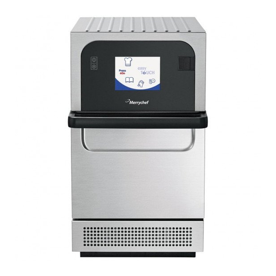
- Page 1 Microwave Combination Oven Read instructions before use Merrychef eikon e2s Service and Repair Manual UL – Original, USA / CAN Part Number 32Z3936...
-
Page 2: Table Of Contents
Contents Contents General information Important Information Renseignements importants à lire avant l'utilisation Environmental protection Identifying your microwave combination oven Structure of technical documentation About this Service and Repair Manual Design and function Design and function of the microwave combination oven Layout and function of the operating panel For your safety Basic safety code... - Page 3 Contents Cleaning chemicals Items required for cleaning Safe working when cleaning Cleaning procedures 7.5.1 Cool down procedure before cleaning 7.5.2 Cleaning instructions Technical data Technical data Dimensional drawings Diagnostics Checking the condition of your appliance Errors and diagnostics Fault finding Tests 10.1 Safe working when testing components...
-
Page 4: General Information
1 General information General information Purpose of this chapter This chapter shows you how to identify your microwave combination oven and provides guidance on using this manual. Contents This chapter contains the following topics: Page Important Information Renseignements importants à lire avant l'utilisation Environmental protection Identifying your microwave combination oven Structure of technical documentation... -
Page 5: Important Information
1 General information 1.1 Important Information ® Users are cautioned that maintenance and repairs should be performed by a Merrychef authorised ® ® service agent using genuine Merrychef replacement parts. Merrychef will have no obligation with respect to any product that has been improperly installed, adjusted, operated or not maintained in accordance with national and local codes or installation instructions provided with the product, or any product that has its serial number defaced, obliterated or removed, or which has been modified or repaired using unauthorised parts or by unauthorised service agents. -
Page 6: Identifying Your Microwave Combination Oven
1 General information 1.4 Identifying your microwave combination oven Position of nameplate The nameplate is located on the rear of your microwave combination oven. 1 Model number eikon e2s 2 Elements of the item Label Meaning number Model Power output 2200W convection 2200W / 1300W... -
Page 7: Structure Of Technical Documentation
1 General information 1.5 Structure of technical documentation Contents The technical documentation for the microwave combination oven includes the following documents: Installation and Operating Manual Service and Repair Manual (this document) 1.6 About this Service and Repair Manual Purpose This Service and Repair Manual is intended for all trained service technicians who work with the mi- crowave combination oven, and provides them with the necessary information for carrying out servicing... - Page 8 1 General information Chapter/section Purpose Setting up the appliance Explains how to unpack the appliance and specifies the parts supplied with the appliance Explains how to set up the appliance Installation Provides information on installing the electrical supply Preparing the appliance for use Explains the procedure for preparing the appliance for first-time use ...
- Page 9 1 General information Présentation des avertissements Les avertissements sont catégorisés selon les niveaux de risque suivants : Niveau de risque Conséquences Probabilité Mort/ blessures graves (irréversibles) Imminent Mort/ blessures graves (irréversibles) Eventuellement Blessure légère (réversible) Eventuellement REMARQUE Dommages matériels Eventuellement Decimal points Decimal points are used throughout this manual in any language available.
-
Page 10: Design And Function
2 Design and function Design and function Purpose of this chapter This chapter describes the design and construction of the microwave combination oven and explains its functions. Contents This chapter contains the following topics: Page Design and function of the microwave combination oven Layout and function of the operating panel eikon e2s Service and Repair Manual UL... -
Page 11: Design And Function Of The Microwave Combination Oven
2 Design and function 2.1 Design and function of the microwave combination oven Parts and their function Item Name Function ON/OFF appliance switch Used to turn the microwave combination oven on and off. Turning this switch off does not isolate the appliance from the electricity supply. -
Page 12: Layout And Function Of The Operating Panel
2 Design and function Item Name Function Door seals The door seals ensure a tight seal around the door. Always keep them clean and check regularly for signs of damage. At the first sign of wear have them replaced by a Merrychef approved service agent. See 'Cleaning procedures' on page 68. -
Page 13: For Your Safety
3 For your safety For your safety Purpose of this chapter This chapter provides you with all the information you need in order to use the microwave combination oven safely without putting yourself or others at risk. This is a particularly important chapter that you must read through carefully. Contents This chapter contains the following topics: Page... -
Page 14: Basic Safety Code
3 For your safety 3.1 Basic safety code Object of this safety code This safety code aims to ensure that all persons who use the microwave combination oven have a thorough knowledge of the hazards and safety precautions, and that they follow the warning notices given in the user manual and on the appliance. -
Page 15: Important Safety Instructions
3 For your safety Working with the microwave combination oven Follow the instructions below: Only those persons who satisfy the requirements stipulated in this installation and operating manual are permitted to use the microwave combination oven. Only use the microwave combination oven for the specified use. Never, under any circumstances, use the microwave combination oven for other purposes. - Page 16 3 For your safety Precautions when using the microwave combination oven When handling hot liquids, foods and containers, care should be taken to avoid scalds and burns. Liquids, such as water, coffee or tea are able to be overheated beyond the boiling point without appearing to be boiling.
-
Page 17: Save These Instructions
3 For your safety Requirements relating to the operating condition of the microwave combination oven As with all electrical appliances, it is recommended to have the electrical connections inspected at least once a year. Never remove the external covers of the appliance. ... - Page 18 3 For your safety DIRECTIVES IMPORTANTES PORTANT SUR LA SÉCURITÉ Lors de l’utilisation d’appareils électriques, des précautions sécuritaires fondamen- tales doivent être prises incluant ce qui suit : Pour réduire les risques de brûlures, de chocs électriques, d’incendie, de blessures corporelles ou d’exposition excessive à...
- Page 19 3 For your safety 16. Pour réduire les risques d’incendie dans la cavité: i) Ne pas faire trop cuire les aliments. Surveiller l’appareil avec soin si des matériaux de papier, de plastique ou autres matériaux combustibles sont placés dans le four pour faciliter la cuisson.
- Page 20 3 For your safety 31. L’appareil n’est pas conçu pour être utilisé par les enfants ou les personnes in- firmes sans supervision. 32. Les enfants devraient être surveillés pour s’assurer qu’ils ne jouent pas avec l’appareil. PRÉCAUTIONS À PRENDRE 1. Lire ce manuel au complet avant d’utiliser votre four. 2.
- Page 21 3 For your safety More on this ... Related topics Summary of hazards Hazards and safety precautions during cleaning Hazards and safety precautions when moving the appliance Hazards and safety precautions when setting up the appliance ...
-
Page 22: Exposure To Excessive Microwave Energy
3 For your safety IMPORTANT To Service Technicians: PRECAUTIONS TO BE OBSERVED BEFORE AND DURING SERVICING TO AVOID POSSIBLE EXPOSURE TO EXCESSIVE MICROWAVE ENERGY. Do not operate or allow the oven to be operated with the door open. Make the following safety checks on all ovens to be serviced before activating the magnetron or other microwave source, and make repairs as necessary: 1) interlock operation, 2) proper door closing,... -
Page 23: Intended Use Of Your Microwave Combination Oven
3 For your safety 3.2 Intended use of your microwave combination oven Intended use of your microwave combination oven The microwave combination oven must only be used for the purposes specified below: The microwave combination oven is designed and built solely for cooking different foodstuffs in containers approved by the manufacturer. -
Page 24: Warning Signs On Your Microwave Combination Oven
3 For your safety 3.3 Warning signs on your microwave combination oven Warning and safety signs eikon e2s Service and Repair Manual UL... - Page 25 3 For your safety Mandatory warning signs The following warning signs / notices must be attached to the microwave combination oven and optional accessories in the area indicated so as to be easily visible at all times. Area Warning sign Description Microwaves warning There is a risk of external and internal burns of body parts following exposure to...
- Page 26 3 For your safety Safety symbols The following safety symbols be attached to the microwave combination oven and optional accessories in the area indicated so as to be easily visible at all times. Area Safety symbol Description Protective Earth (Ground) Symbole de sécurité...
-
Page 27: Summary Of Hazards
3 For your safety 3.4 Summary of hazards General rules for dealing with hazards and safety precautions The microwave combination oven is designed to protect the user from all hazards that can reasonably be avoided by design measures. The actual purpose of the microwave combination oven, however, means that there are still residual risks;... - Page 28 3 For your safety Hot steam / vapour (2) When cooking food the microwave combination oven may generate hot steam and vapour which escapes when the appliance door is opened and which is removed through the air vents on the rear of the microwave combination oven when the appliance door is closed.
-
Page 29: Aperçu Des Risques
3 For your safety 3.5 Aperçu des risques Règles générales en cas de risques et mesures de sécurité Le four mixte est conçu tel que l'utilisateur est raisonnablement protégé de tous les risques de con- struction évitables. Dû à l'objet du four mixte, il existe cependant des risques résiduels contre lesquels vous devez prendre des mesures de précaution pour les éviter. - Page 30 3 For your safety Vapeur / buées chaudes (2) Le four micro-ondes combiné génère de la vapeur et des buées chaudes qui s'échappent à l'ouverture de la porte de l'appareil et qui, à porte d'appareil fermée, sont évacuées par les manchons d'évacuation d'air vicié, en arrière du four.
-
Page 31: Hazards And Safety Precautions When Moving The Appliance
3 For your safety 3.6 Hazards and safety precautions when moving the appliance Safety hazard: moving heavy weights Danger Where or in what situations does the Preventive action hazard arise? Risk of injury from over- When moving the appliance onto and off Use a forklift truck or pallet truck stressing your body the moving equipment... -
Page 32: Hazards And Safety Precautions When Setting Up The Appliance
3 For your safety 3.7 Hazards and safety precautions when setting up the appliance Safety hazard: moving heavy weights Danger Where or in what situations does the Preventive action hazard arise? Risk of injury from over- When moving the appliance Use a forklift truck or pallet truck to stressing your body place the appliance in the installation... -
Page 33: Hazards And Safety Precautions During Installing
3 For your safety 3.8 Hazards and safety precautions during installing Safety hazard: electrical power Danger Where or in what situations does the Preventive action hazard arise? Risk of electric shock from Under covers Work on the electrical system must only live parts be performed by qualified electricians ... -
Page 34: Hazards And Safety Precautions When Preparing Appliance For Use
3 For your safety 3.9 Hazards and safety precautions when preparing appliance for Safety hazard: electrical power Danger Where or in what situations does the Preventive action hazard arise? Risk of electric shock from Work on the electrical system must only Under covers live parts ... -
Page 35: Hazards And Safety Precautions During Cleaning
3 For your safety 3.10 Hazards and safety precautions during cleaning Safety hazard: cleaning chemicals Danger Where or in what situations does the Preventive action hazard arise? Risk of chemical burns or For all cleaning actions Do not let cleaning chemicals come irritation to skin, eyes and into contact with your skin or eyes respiratory system from... - Page 36 3 For your safety Safety hazard: moving appliances supported on a wheeled base Danger Where or in what situations does the Preventive action hazard arise? All specified hazards While appliances are being moved on a When moving the microwave combina- wheeled platform tion oven, take care not to wheel over the electrical supply cables...
-
Page 37: Hazards And Safety Precautions During Servicing And Repair
3 For your safety 3.11 Hazards and safety precautions during servicing and repair Safety hazard: heat Danger Where or in what situations does the Preventive action hazard arise? A risk of burns from hot Inside the entire cavity, including all parts Before starting cleaning tasks, wait surfaces that are or were inside during cooking,... - Page 38 3 For your safety Safety hazard: moving heavy weights Danger Where or in what situations does the Preventive action hazard arise? Risk of injury from over- When moving the appliance Use a forklift truck or pallet truck to stressing your body place the appliance in the installation position or to move it to a new position ...
-
Page 39: Hazards And Safety Precautions When Taking The Appliance Out Of Service
3 For your safety 3.12 Hazards and safety precautions when taking the appliance out of service Safety hazard: electrical power Danger Where or in what situations does the Preventive action hazard arise? Risk of electric shock from Work on the electrical system must only Under covers live parts ... -
Page 40: Safety Devices
3 For your safety 3.13 Safety devices Meaning The microwave combination oven has a number of safety devices to protect the user from hazards. It is absolutely essential that all safety devices are fitted and in working order when operating the appliance. Position and function Item Safety device... - Page 41 3 For your safety Item Safety device Function Check Action: Disconnection device Installed by the customer close to the appliance; easily visible Trip the disconnection device (no picture, and accessible, 1- or 3-pole installed by action, minimum contact separa- customer) tion 3 mm.
-
Page 42: Requirements To Be Met By Personnel And Working Positions
3 For your safety 3.14 Requirements to be met by personnel and working positions Requirements to be met by operating personnel Personnel Qualifications Tasks Service technician Is an authorized service agent All servicing and repair work Has relevant technical training ... -
Page 43: Personal Protective Equipment
3 For your safety 3.15 Personal protective equipment Moving and setting up the appliance Activity Materials used Personal protective equipment Conveying within the establishment Suitable lifting gear Protective gloves Setting up the appliance on a work Forklift truck or pallet Safety boots surface, stand or in a stacking kit... - Page 44 3 For your safety Repairs Activity Protection equipment All repair work Work wear and personal protective equipment depending on the job that needs doing as specified in national regulations eikon e2s Service and Repair Manual UL...
-
Page 45: Équipement De Protection Individuelle
3 For your safety 3.16 Équipement de protection individuelle Transport et montage Action Moyen utilisé Équipement de protection individuelle Transport au sein de l'entreprise Engins de levage adaptés Gants de protection Montage de l'appareil sur le plan de Chariots élévateurs ou Chaussures de sécurité... - Page 46 3 For your safety Nettoyage Action Nettoyant utilisé Équipement de protection individuelle Nettoyage de l'enceinte de cuisson à la Nettoyant approuvé de Les éléments de l'équipement de main Merrychef protection dépendent du produit de nettoyage utilisé : ...
-
Page 47: Setting Up The Appliance
4 Setting up the appliance Setting up the appliance Purpose of this chapter This chapter provides information on how to set up your appliance. This chapter is intended for the user and for a qualified member of staff from an authorized service company. -
Page 48: Safe Working When Setting Up The Appliance
4 Setting up the appliance 4.1 Safe working when setting up the appliance For your safety Before starting work, familiarize yourself with the hazards described in 'Hazards and safety precautions when setting up the appliance' on page 32. Eligibility of personnel for setting up the appliance Personnel eligible for setting up the appliance: ... -
Page 49: Requirements For The Installation Location
4 Setting up the appliance 4.2 Requirements for the installation location Meaning This section contains information to help you choose a suitable installation location for the microwave combination oven. Inspect the intended installation location carefully to ensure it is suitable before taking the appliance there and starting the installation. - Page 50 4 Setting up the appliance Minimum space required The following diagram and table show the space required for the appliance for different installation and operating situations. They also show the minimum horizontal distances from adjacent walls and sur- faces. The safety clearance on the top must always be complied with. Meaning Space required Safety clearance from the top...
-
Page 51: Mounting The Appliance On A Work Surface
4 Setting up the appliance 4.3 Mounting the appliance on a work surface Rules for setting up the appliance safely Observe the following rules to ensure that the appliance is installed in a stable situation: It must be possible to set up the work surface in the installation position so that it cannot tip over or slide about. -
Page 52: Installation
5 Installation Installation Purpose of this chapter This chapter explains how to connect your microwave combination oven to the electrical supply. Contents This chapter contains the following topics: Page Safe working during electrical installation Planning the electrical installation eikon e2s Service and Repair Manual UL... -
Page 53: Safe Working During Electrical Installation
5 Installation 5.1 Safe working during electrical installation For your safety Before starting work, familiarize yourself with the hazards described in 'Hazards and safety precautions during installation' on page 33. Eligibility of personnel for the electrical installation Only electricians qualified under the terms of EN 50110-1 and from an authorized service company are permitted to perform work on electrical equipment. -
Page 54: Planning The Electrical Installation
5 Installation 5.2 Planning the electrical installation Meaning It is crucial to the safe and reliable operation of the appliance that the electrical system is installed carefully and correctly. All the rules and regulations listed here, and the described procedure, must be strictly followed. - Page 55 5 Installation GROUNDING INSTRUCTIONS IMPROPER USE OF THE GROUNDING PLUG CAN RESULT IN A RISK OF ELECTRIC SHOCK. For all cord-connected appliances: GROUNDING INSTRUCTIONS This appliance must be grounded. In the event of an electrical short circuit, grounding reduces the risk of electric shock by providing an escape wire for the electric current.
- Page 56 5 Installation Plug types Power Supply Configuration (refer to nameplate) Model e2S**MV6******** 208V / 240V AC, 60Hz, 30Amp, 2P + GND (High Power version) Plug Type NEMA 6-30P Plug Type NEMA L6-30P Model e2S**MV6******** 208V / 240V AC, 60Hz, 20Amp, 2P + GND (Standard Power version) Plug Type NEMA 6-20P...
-
Page 57: Preparing The Appliance For Use
6 Preparing the appliance for use Preparing the appliance for use Purpose of this chapter This chapter shows you how to put the microwave combination oven into operation and how to cook. Contents This chapter contains the following topics: Page Safe working when preparing the appliance for use Procedure for preparing the appliance for use Start page... -
Page 58: Safe Working When Preparing The Appliance For Use
6 Preparing the appliance for use 6.1 Safe working when preparing the appliance for use For your safety when preparing the appliance for use Before starting work, make sure that you are familiar with the hazards described under 'Hazards and safety precautions when preparing appliance for use' on page 34 and in the chapter 'For your safety' in the user manual. - Page 59 6 Preparing the appliance for use Hot steam / vapour Risk of scalding from hot steam and vapour When opening the door, always be cautious of escaping hot steam and vapour which can cause scalding to face, hands, feet and legs. ...
- Page 60 6 Preparing the appliance for use Interférences radio REMARQUE Ce produit appartient à la classe A. Dans un environnement domestique, ce produit est susceptible de provoquer des interférences radio, auquel cas l'utilisateur peut être amené à prendre les mesures adéquates. EN CAS D’INTERFÉRENCES DANS LES SIGNAUX DE RADIO/ TÉLÉVISION Cet équipement génère et utilise de l’énergie FR et s’il n’est pas installé...
-
Page 61: Procedure For Preparing The Appliance For Use
6 Preparing the appliance for use 6.2 Procedure for preparing the appliance for use Checks prior to preparing the appliance for use Before preparing the microwave combination oven for use use the checklists below to make sure that all important requirements are met. The appliance must not be put into operation until all the specified requirements are met. - Page 62 6 Preparing the appliance for use Ustensiles de cuisson appropriés Les directives du fabricant devraient être consultées pour déterminer l’adéquation de chaque contenant et ustensile individuel pour chacune des fonctions de la cuisson. Le tableau suivant présente les directives générales : Ustensiles de cuisson Approprié...
- Page 63 6 Preparing the appliance for use Start up Make all the relevant safety checks and ensure the appliance is clean and empty. Then switch the appliance ON. ® The easyToUCH screen illuminates with the display briefly showing the serial number and appliance data. If required, to keep the data on the screen, lightly tap the screen once to freeze the display.
-
Page 64: Start Page
6 Preparing the appliance for use 6.3 Start page Appearance The buttons and what they do Function Button Meaning Development Mode 'Development Mode' enables multistage cooking profiles to be developed, then stored under a name and symbol for reuse. Press&Go 'Press&Go' allows quick access to use the cooking profiles that are already stored. -
Page 65: The Keyboard Screen
6 Preparing the appliance for use 6.4 The keyboard screen Appearance The buttons and their functions Button Meaning Function Keyboard screen Keyboard screen is used to enter an authorised password to enter data for programs and may restrict operator access to some functions. -
Page 66: Using A Usb Stick
6 Preparing the appliance for use 6.5 Using a USB stick Purpose of the USB cover The USB cover protects the USB port so that no water vapour can get into the control electronics during cooking or cleaning. During cooking and cleaning, there must not be a USB stick inserted and the USB port must be closed by the cover. - Page 67 6 Preparing the appliance for use Switch the appliance ON. The files automatically download from the USB memory stick showing the progress and confirmation screens for the update. On completion the appliance displays the start up screen. Then the thermometer symbol is displayed. Remove the USB memory stick and keep it in a safe place.
-
Page 68: Cleaning Procedures
7 Cleaning procedures Cleaning procedures Purpose of this chapter This chapter summarizes the cleaning methods, the cleaning chemicals and how to handle them and the cleaning instructions. It explains the correct procedure to follow when cleaning the microwave combi- nation oven. Contents This chapter contains the following topics: Page... -
Page 69: Daily Cleaning Tasks
7 Cleaning procedures 7.1 Daily cleaning tasks What must be cleaned? Procedure Cleaning chemicals Cavity Clean by hand with a soft cloth / Cleaning and protective chemicals paper towel approved by the manufacturer Outside of appliance Clean by hand with a soft cloth Common household stainless steel cleaner or hard surface cleaner ... -
Page 70: Items Required For Cleaning
7 Cleaning procedures 7.3 Items required for cleaning Items required for cleaning Merrychef cleaning chemical Merrychef protective chemical Protective rubber gloves Non-abrasive nylon scrub pad Cleaning towel and cloths Eye protection Heat proof gloves (optional) ... -
Page 71: Safe Working When Cleaning
7 Cleaning procedures 7.4 Safe working when cleaning Your safety and the safety of your staff Before your personnel start working with the microwave combination oven for the first time, familiarize yourself with the information contained in the chapter 'For your safety' on page 13 and make relevant safety arrangements. - Page 72 7 Cleaning procedures Spraying water into a hot cavity Risk of scalding from hot steam If water is sprayed into the hot cavity, steam will be produced that may scald. Before starting cleaning tasks, wait until the cavity has cooled to below 50°C / 122°F or use the 'Cool Down' function to cool the cavity.
-
Page 73: Cleaning Procedures
7 Cleaning procedures 7.5 Cleaning procedures Cleaning the microwave combination oven This section explains how to clean your microwave combination oven. Contents This section contains the following topics: Page Cool down procedure before cleaning Cleaning instructions eikon e2s Service and Repair Manual UL... -
Page 74: Cool Down Procedure Before Cleaning
7 Cleaning procedures 7.5.1 Cool down procedure before cleaning For your safety when cleaning Before starting cleaning work, it is essential that you familiarize yourself with the rules and hazard warnings specified in 'Safe working when cleaning' on page 71, and follow the instructions given there. Purpose With the optional 'cool down' function you can cool down the cavity quickly for cleaning your microwave combination oven sooner. - Page 75 7 Cleaning procedures Taking all necessary precautions place a suitable tray of ice cubes into the hot cavity. This speeds up the cooling process. Press the green tick to continue. The cooling progress is displayed and takes approximately 20 minutes. To reduce the cool down time to about 20 minutes leave the appliance door open slightly during the cooling process.
-
Page 76: Cleaning Instructions
7 Cleaning procedures 7.5.2 Cleaning instructions For your safety when cleaning Before starting cleaning work, it is essential that you familiarize yourself with the rules and hazard warnings specified in 'Safe working when cleaning' on page 71, and follow the instructions given there. Requirements for cleaning the appliance ... - Page 77 7 Cleaning procedures For difficult areas, leave to soak for 10 minutes with the appliance door open. Use a non-abrasive nylon scrub pad/sponge to clean all surfaces of the cavity including the roof and the inside surface of the appliance door. NOTICE: Do not scrub the door seal or use metallic scourers.
- Page 78 7 Cleaning procedures Applying the protective chemical, cleaning the air filter After completing the cleaning procedures press the green tick to confirm that the cavity has been cleaned. You can then apply a protective chemical to make cleaning easier the next day (optional). Spray protective chemical approved by Merrychef onto a clean sponge.
- Page 79 7 Cleaning procedures Replace all mobile parts into the cavity that had been removed for cleaning. Close the appliance door. Press the green check mark to confirm application of the protec- tive chemical. A prompt appears asking to clean the air filter. Tilt the faceplate below the appliance door downwards.
- Page 80 7 Cleaning procedures Remove the air filter. Clean the air filter with a damp cloth. Replace the air filter and tilt the faceplate in its original position. Clean the oven exterior with a damp cloth. Press the green check mark to confirm cleaning of the air filter. The oven switches OFF.
-
Page 81: Technical Data
8 Technical data Technical data Purpose of this chapter This chapter contains the technical data for your microwave combination oven. Contents This chapter contains the following topics: Page Technical data Dimensional drawings eikon e2s Service and Repair Manual UL... -
Page 82: Technical Data
8 Technical data 8.1 Technical data Dimensions and weights Width Including packaging [in] 21.1 [mm] Appliance without packaging [in] 14.0 [mm] Height Including packaging [in] 33.5 [mm] Appliance ("Classic" exterior) without packaging [in] 24.4 [mm] Appliance ("Trend" exterior) without packaging [in] 25.4 [mm]... - Page 83 8 Technical data Electrical connected load ratings – Standard Power version Electrical supply 2~ 208V / 240V 60Hz Connections used 2P + GND Arrangement Two Pole Rated power 3120 / 4160 consumption Rated current per phase 15 / 20 Power output Rated power output 1300 / 2200 convected heat...
-
Page 84: Dimensional Drawings
8 Technical data 8.2 Dimensional drawings eikon e2s Front view (door closed) Cavity dimensions (door closed) View from the top (door closed) View from the right hand side (door open) eikon e2s Service and Repair Manual UL... -
Page 85: Diagnostics
9 Diagnostics Diagnostics Purpose of this chapter This chapter contains information on checking various functions of your microwave combination. Contents This chapter contains the following topics: Page Checking the condition of your appliance Errors and diagnostics Fault finding eikon e2s Service and Repair Manual UL... -
Page 86: Checking The Condition Of Your Appliance
9 Diagnostics 9.1 Checking the condition of your appliance Servicing procedure: overview Disconnect/isolate the appliance from the power supply. Check the appliance is correctly installed as described in the “Installation” section of this manual. Visually check the cleanliness/condition of the power supply/cable/gland, casing, cavity and door of the appliance for signs of wear, damage, distortion etc. - Page 87 9 Diagnostics Enter the service password, for example, "SERVICE" on the keypad. Select OK to display the Error Log, service information and test options. Touchscreen Calibration Apply continuous light pressure to the screen while switching the appliance on. Continue to hold until the progress bar has completed. Using a non-abrasive pointer, such as a ball point pen, accurately press the centre of each crosshair displayed on the screen.
- Page 88 9 Diagnostics If the crosshairs turn green three times consecutively the cali- bration process is completed successfully. Once calibrated the screen will display information about the appliance. Functions of the Service Mode Check the "Error Log" for details of any logged appliance errors. Check the "Oven Counters"...
-
Page 89: Errors And Diagnostics
9 Diagnostics Perform the tests of your microwave combination oven as de- scribed. See “Tests” section of this manual. If required refer to the “Replacing components” section for any repairs needed before continuing with the tests. Follow the procedures under “Commissioning the appliance” before commissioning your appliance for use. - Page 90 9 Diagnostics Copying error messages Enter settings menu and select the USB symbol. The USB screen appears. Open the cover of the USB port and insert the USB memory stick into the slot. NOTE: The USB memory stick may take several seconds to load before the screen will respond.
- Page 91 9 Diagnostics Select ‘Error Log’ on the following screen. Select the green check mark to copy the error log to the USB memory stick. The upload progress is shown followed by the upload status. Select backspace 3 times to return to the main menu. Remove the USB memory stick.
- Page 92 9 Diagnostics Scroll down the list (if necessary) and select an error from the list to display individual records. Error details include: component description, error caused, date and time of the error with details of failure and range. Select backspace to return to the list, again to return to the Service Menu.
- Page 93 9 Diagnostics Visual View Select 'Visual View' to check the main components of the appli- ance. Select a component symbol to switch on (red). Select again to increase the level or turn off (green). Remove the air filter at the front of the oven. The colour of the air filter symbol on the display should change from green to red indicating that the magnetic reed switch circuit for the air filter is operating correctly.
- Page 94 9 Diagnostics Open the oven door. Check the colour of the door symbol changes from green to red on the display to check the door microswitch / interlock circuit is operating. Place door spacers onto the oven door (refer to "Adjusting the door microswitches / interlocks"...
- Page 95 9 Diagnostics Select the convection fan and check if it is operating correctly. When increasing the fan power gradually to 100% the fan noise should become louder. Select the heater, it increases to maximum temperature and then cycles (the convection fan is ON by default). Check the cavity temperature and heater element current draw at maximum are correct.
-
Page 96: Fault Finding
9 Diagnostics 9.3 Fault finding Hardware control components Operations communication: The oven has two main parts being the QTS assembly (keyboard, screen, logic) and the SRB (Smart Relay Board to switch and monitor the required operation). The QTS is the master of the oven and instructs the SRB what to do, in turn the SRB communicates information on the operation back to the QTS. - Page 97 9 Diagnostics Error code list Error Error Description Trigger Possible System Code Condition Causes Response E 101 Magnetron Detects a magne- The current Failure of com- Display error failed to tron is not working measured by the ponent/s in the message until energise correctly...
- Page 98 9 Diagnostics E 108 QTS PM Wrong PM found / The QTS or SRB The PM has been Display error error no PM found either has an changed and is message until incorrect PM incorrect. The PM system is power (Personality Mod- has been re- cycled.
- Page 99 9 Diagnostics Screen Touch screen Continual pres- Damaged touch Display error frozen inoperable sure of the touch screen / touch message until screen screen depress for touch screen more than 15 press released seconds. Error code for recommission test messages 89 Cooling test fail 90 Convection test fail 92 Heater test fail...
-
Page 100: Tests
10 Tests 10 Tests Purpose of this chapter This chapter contains information on testing single components of your microwave combination oven. Contents This chapter contains the following topics: Page Safe working when testing components Requirements Testing selected components (casing mounted) High voltage components (casing removed) Mains voltage components (casing removed) eikon e2s Service and Repair Manual UL... -
Page 101: Safe Working When Testing Components
10 Tests 10.1 Safe working when testing components For your safety when testing oven components Before starting oven tests, it is essential that you familiarize yourself with the rules and hazard warnings specified and follow the instructions given there. Eligibility of personnel for testing oven components Only qualified personnel from an authorized service company are permitted to test components of the microwave combination oven. - Page 102 10 Tests INSTRUCTIONS POUR LA MISE À LA TERRE LE MANQUEMENT À CETTE RÈGLE PEUT RÉSULTER EN DES CHOCS ÉLECTRIQUES POUVANT CAUSER LA MORT. Pour tous les appareils avec cordon: INSTRUCTIONS POUR LA MISE À LA TERRE Cet appareil doit être mis à la terre. Si un court-circuit électrique survient, la mise à la terre réduit les risques de chocs électriques en offrant un conducteur de fuite pour le courant électrique.
- Page 103 10 Tests Hot surfaces Risk of burns from high temperatures inside the cavity and on the inside of the appliance door You may get burnt if you touch any of the interior parts of the cooking chamber, the inside of the appliance door or any parts that were inside the oven during cooking.
-
Page 104: Requirements
10 Tests 10.2 Requirements Equipment required for testing the appliance Portable Appliance Tester (P.A.T.) Digital Multi-Meter (D.M.M.) Megger / similar 500 V d. c. resistance meter Microwave detection / leakage meter Temperature reader Continuity meter ... - Page 105 10 Tests Earth/Insulation test Check that the following requirements have been met: The appliance has been disconnected from the power supply and protective measures have been taken to ensure the power cannot be switched on again. Connect the mains lead from the appliance to a Portable Appli- ance Tester.
- Page 106 10 Tests Microwave Power test: Measuring the microwave power output of the magnetron(s) Check that the following requirements have been met: The appliance is cool. NOTE: The power output is established under IEC 705 standard method which is only workable in laboratory controlled conditions.
- Page 107 10 Tests When the countdown has finished, remove the container from the cavity. Immediately stir with a plastic implement and measure the water temperature. Calculate the temperature rise of the water (end temperature minus the start temperature). The temperature rise should be 14.3°C (25.7°F) ±10% for the 1000W (1 magnetron) variant.
- Page 108 10 Tests Microwave Leakage test Follow these instructions when measuring: Make sure that the survey meter you are using has been calibrated and is suitable for measuring frequencies of 2,450 MHz. Do not exceed meter full scale deflection. The leakage meter should initially be set to the highest scale, then adjusted down as necessary to ensure that low readings are measured on the most sensitive range.
- Page 109 10 Tests Move the survey meter probe across all casework joins and vent areas including those marked in yellow, shown opposite. When the magnetron circuit stops after 30 seconds, change the water and re-select the test to continue. Select the red ‘X’ on the display to stop the test at any time. Readings must be below 5 mW/cm².
- Page 110 10 Tests Temperature Control test: measuring the cavity temperature NOTE: Re-calibrating the temperature sensor / thermocouple with the SRB is normally only required when the thermocouple has been replaced or the appliance is under or over cooking. Place the probe of a temperature reader onto a heat sink or a metal plate in the centre of the oven cavity and close the door.
- Page 111 10 Tests If the temperature reading is different to the maximum set point, scroll up to select TEMP. COMP. (Temperature Compensation) and enter the password. Enter the figure from the temperature reader on the keypad and select OK to calibrate the SRB to the temperature sensor (ther- mocouple).
- Page 112 10 Tests If the temperature reading is unstable: Disconnect and isolate the appliance from the electricity supply. Take protective measures to ensure the power cannot be switched on again. Allow the appliance to cool down. Remove the side and top panels of the casing. Check the cavity temperature sensor wire and connections.
-
Page 113: High Voltage Components (Casing Removed)
10 Tests 10.4 High voltage components (casing removed) High Voltage Transformer test Ensure the following requirements have been met before starting the test: The appliance has been disconnected from the power supply and protective measures have been taken to ensure the power cannot be switched on again. ... - Page 114 10 Tests High Voltage Diode test Ensure the following requirements have been met before starting the test: The appliance has been disconnected from the power supply and protective measures have been taken to ensure the power cannot be switched on again. ...
- Page 115 10 Tests Connect the DMM to one terminal and the metal outer case of the high voltage capacitor. The test is passed if the DMM display reads "open circuit". Repeat the test for the other terminal and the metal outer case. Using a megger, test the insulation resistance between both terminals and the metal outer case of the high voltage capacitor.
-
Page 116: Mains Voltage Components (Casing Removed)
10 Tests 10.5 Mains voltage components (casing removed) Convection fan: motor The convection fan motor is a 3-phase AC motor having a maximum speed of 7200 rpm controlled by a motor speed controller. The windings are thermally protected and in the event of a thermal fault a trip inside the motor will operate and shut down the motor speed controller. -
Page 117: Firmware
11 Firmware 11 Firmware Purpose of this chapter This chapter informs about the correct procedure to check and update the firmware of the appliance. Page Firmware Updates eikon e2s Service and Repair Manual UL... -
Page 118: Firmware Updates
11 Firmware 11.1 Firmware Updates Overview Switch on the oven. Tap the top right hand corner of the screen. Enter the correct password (the default password is "MANAGER") and select the green check mark. Select the USB symbol. Select one of the USB options: ... - Page 119 11 Firmware Select the firmware to install and select the green check mark to confirm. The update screen displays the file version and product. Select the green check mark to confirm the installation. eikon e2s Service and Repair Manual UL...
- Page 120 11 Firmware Requirement: To format a USB memory stick, place it in a PC USB slot, select 'Computer' and right click on the USB memory stick symbol. Select 'Format' and select FAT (Do NOT select FAT 32). NOTE: This will erase all data on the USB memory stick. Procedure: With the oven switched OFF, open the cover of the USB port and insert the USB memory stick into the slot.
- Page 121 11 Firmware Select the USB symbol. Once the USB memory stick has stopped flashing, select the 'Firmware' USB symbol. The current QTS (Quick Touch Screen) and SRB (Smart Relay Board) firmware versions are displayed at the top left of the screen.
- Page 122 11 Firmware SRB firmware update Select the ‘SRB’ file with the correct file version number. NOTE: A tinted band over a file name indicates the file is not valid for your oven. Check if the file information shown is correct before selecting OK. If not select ‘X’...
- Page 123 11 Firmware The SRB file is checked and the download progress from the USB is displayed followed by the update status and confirmation screens. NOTE: Wait until all files have been loaded. Do not touch the oven until the end of the downloading process. When the download process is complete press the return arrow and select the QTS file and repeat.
- Page 124 11 Firmware QTS firmware update Select the ‘QTS’ file with the correct file version number. NOTE: A tinted band over a file name indicates the file is not valid for that appliance. Check if the file information shown is correct before selecting OK. If not, select ‘X’...
- Page 125 11 Firmware Check if the screen shows the correct QTS version. If not, repeat the process using the correct file. Remove the USB memory stick and keep it in a safe place. Download Procedure NOTICE Do not remove the USB memory stick during the download sequence as this could corrupt the USB data.
- Page 126 11 Firmware Tap the top right of the screen to bypass the preheat stage. Enter the password and select OK to display the settings menu. Select the USB symbol. Select the 'Firmware' USB symbol. eikon e2s Service and Repair Manual UL...
- Page 127 11 Firmware Select the ‘QTS’ file with the correct file version number. NOTE: A tinted band over a file name indicates the file is not valid for that appliance. Check the file information shown is correct before selecting the green check mark. If not, select ‘X’...
- Page 128 11 Firmware The CBR file is checked and the download progress from the USB memory stick is displayed followed by the update status and confirmation screens. eikon e2s Service and Repair Manual UL...
- Page 129 11 Firmware The QTS, SRB and Application Icon files then download auto- matically showing the progress, status and reboot confirmation screens for each file update. eikon e2s Service and Repair Manual UL...
- Page 130 11 Firmware On completion the start up screen is displayed showing the updated firmware versions followed by the pre-heat temperature screen. Confirming the firmware update After an update of the appliance firmware certain files are copied back to the USB memory stick. You can check if the file transfer was successful with the following procedure: Load the files from the USB memory stick to a computer.
- Page 131 11 Firmware PM (Personality Module) replacement – firmware update NOTE: The Personality Module on the SRB contains the firmware. The Personality Module on the QTS contains the firmware, serial number of your appliance, tem- perature calibration, cooking profiles, application icons and the recipe images. With a new Personality Module fitted and casing refitted, switch on the appliance and tap the screen to hold and check the QTS and SRB versions are the latest release.
- Page 132 11 Firmware Open the cover to the USB port and insert the USB memory stick into the slot. NOTE: The USB memory stick may take several seconds to load before the screen will respond. Once the USB memory stick has stopped flashing, select the required "USB Recipes"...
- Page 133 11 Firmware Check the file information shown is correct before selecting OK. If not, select ‘X’ and locate the correct file. When completed, select menu file to load the cooking profiles. Once the cooking profiles are loaded the appliance restarts. Enter the date and time settings.
-
Page 134: Replacing Components
12 Replacing components 12 Replacing components Purpose of this chapter This chapter contains information on how to remove and fit components of the oven. Contents This chapter contains the following topics: Page Safe working when replacing appliance parts Overview Removing / fitting the casing Removing / fitting the door assembly Replacing a magnetron Replacing the cooling fan... -
Page 135: Safe Working When Replacing Appliance Parts
12 Replacing components 12.1 Safe working when replacing appliance parts For your safety when replacing appliance parts Before starting service / repair work, it is essential that you familiarize yourself with the rules and hazard warnings specified and follow the instructions given there. Eligibility of personnel for removal / fitting of appliance parts Only qualified personnel from an authorized service company are permitted to remove and fit compo- nents of the microwave combination oven. - Page 136 12 Replacing components INSTRUCTIONS POUR LA MISE EN TERRE LE MANQUEMENT À CETTE RÈGLE PEUT RÉSULTER EN DES CHOCS ÉLECTRIQUES POUVANT CAUSER LA MORT. Pour tous les appareils avec cordon: INSTRUCTIONS POUR LA MISE À LA TERRE Cet appareil doit être mis à la terre. Si un court-circuit électrique survient, la mise à la terre réduit les risques de chocs électriques en offrant un conducteur de fuite pour le courant électrique.
- Page 137 12 Replacing components Hot surfaces Risk of burns from high temperatures inside the cavity and on the inside of the appliance door You may get burnt if you touch any of the interior parts of the cooking chamber, the inside of the appliance door or any parts that were inside the oven during cooking.
-
Page 138: Overview
12 Replacing components 12.2 Overview View: left hand side eikon e2s Service and Repair Manual UL... - Page 139 12 Replacing components View: right hand side eikon e2s Service and Repair Manual UL...
- Page 140 12 Replacing components View: rear side eikon e2s Service and Repair Manual UL...
- Page 141 12 Replacing components Component List Item Name Function Front panel The front panel houses the touchscreen and the QTS assembly. Door handle Open the oven door using the door handle. Never use the door handle to lift the appliance. Door cover panel The door cover panel can be detached for accessing the door hinge assembly.
- Page 142 12 Replacing components Item Name Function Cavity thermostat (cavity overheat stat) The thermostat continuously measures the temper- ature in the cavity and prevents it from overheating. Cavity temperature sensor wire (thermocouple) The sensor wire extends between the thermostat entering the cavity and the interior of the cavity.
-
Page 143: Removing / Fitting The Casing
12 Replacing components 12.3 Removing / fitting the casing Tools required M5.5 hex socket wrench Requirements Check that the following requirements have been met: The appliance has been disconnected from the power supply and protective measures have been taken to ensure the power cannot be switched on again. ... - Page 144 12 Replacing components Remove top panel first. Unfasten three M5.5 hex head flange bolts at the back panel of the appliance attaching the top panel to the back panel. Slide the top panel towards the back of the appliance and remove Removing the side panels: Unfasten six M5.5 hex head flange bolts (three per side) at the back panel of the appliance attaching each side panel to the back...
- Page 145 12 Replacing components Fitting the panels of the casing Follow the steps in the reverse order to fit the panels of the casing. eikon e2s Service and Repair Manual UL...
-
Page 146: Removing / Fitting The Door Assembly
12 Replacing components 12.4 Removing / fitting the door assembly Component Tools required Two metal pins (length: 10 mm / 0.4 in) M5.5 hex socket wrench M8 hex socket wrench Requirements Check that the following requirements have been met: The appliance has been disconnected from the power supply and protective measures have been taken to ensure the power cannot be switched on again. - Page 147 12 Replacing components Tilt the oven door to an angle of approx. 30° relative to the ground. Remove the door assembly from the oven performing a rotational movement of lifting the door up and pulling it away from the casing. Unfasten two M5.5 hex head flange bolts next to the door hinges to remove the cover panel from the door frame.
- Page 148 12 Replacing components Turn the door assembly around. Slide the cover panel away from the door handle to remove it from the door frame. Remove the two thermal insulation pads located between the springs attached to the door hinges and the door handle. Unfasten two M8 hex cap screws on each side.
- Page 149 12 Replacing components Remove all insulation pads/mats from the door. Unfasten two M8 hex cap screws. Remove/replace the door hinge units if required. eikon e2s Service and Repair Manual UL...
- Page 150 12 Replacing components Fitting the components of the door assembly Follow the steps in the reverse order to reassemble the compo- nents of the oven door and to fit it to the oven. NOTE: Carefully refit the insulation pads/mats to their original positions. eikon e2s Service and Repair Manual UL...
-
Page 151: Replacing A Magnetron
12 Replacing components 12.5 Replacing a magnetron Component The magnetron(s) is/are located on top of the cavity and is/are fixed to the cooling duct and the cavity roof. The 2000W e2s variant comprises two magnetrons located on the left and right hand sides of the cooling duct. The cooling duct covers one side of the magnetron where the magnetron is attached to the cavity roof with two screws. - Page 152 12 Replacing components The outlet of the cooling duct carries heat to the back of the oven and is covered by a grille. The outlet comprises a sheet metal frame containing holes corresponding to the positions of Pozidriv screws securing the cooling duct to the magnetron.
- Page 153 12 Replacing components Preparing a spare magnetron The spare magnetron comes with four pressed bolts. Remove the bolts before fitting the magnetron to the oven. NOTE: The bolts can be removed by knocking them out of the tabs with a hammer.
- Page 154 12 Replacing components Unfasten one Pozidriv screw on the left side of the cooling duct with a long PZ2 Pozidriv screwdriver using the corresponding access hole at the cooling duct (when looking at the back side of the oven). NOTE: The number of screws on the left side of the cooling duct depends on the number of magnetrons fitted.
- Page 155 12 Replacing components Unfasten four M8 hex cap screws to remove the magnetron. There is one pair of screws on each side of the magnetron. Disconnect any cables leading into the magnetron(s). Fitting a magnetron Follow the steps in the reverse order to fit a spare magnetron. Ensure nothing becomes trapped under the magnetron mounting points (e.
-
Page 156: Replacing The Cooling Fan
12 Replacing components 12.6 Replacing the cooling fan Component The cooling fan is located under the cavity and can be accessed by removing the convection fan motor speed controller. Tools required M7 hex socket wrench Requirements Check that the following requirements have been met: ... - Page 157 12 Replacing components Removing the cooling fan Unplug the electrical connection of the cooling fan on the right hand side of the appliance. Unfasten two M7 hex nuts each securing one arm of the sheet metal bracket which holds the cooling fan. Then turn the bracket clockwise.
-
Page 158: Replacing The Qts (Quick Touch Screen) Assembly
12 Replacing components 12.7 Replacing the QTS (Quick Touch Screen) assembly Component Top section (picture on the left): The QTS (Quick Touch Screen) board lies behind the easyToUCH screen and is attached to the front panel of the oven. Bottom section (picture on the left): The much larger SRB (System Relay Board) extends over the whole width of the oven and rests in a tilted position close to the front panel of the oven. - Page 159 12 Replacing components Removing the QTS assembly Disconnect all cables connecting the QTS assembly to the SRB. Remove the top front panel (including the touchscreen and QTS assembly) from the frame of the casing: Unfasten two M5.5 hex head flange bolts fixing the front panel to the sheet metal frame.
- Page 160 12 Replacing components 1) Slide the front panel upwards. 2) Then carefully pull the front panel away from the sheet metal frame. Double check that all cables connecting the QTS assembly to the SRB have been removed. eikon e2s Service and Repair Manual UL...
- Page 161 12 Replacing components Unfasten four M5.5 hex head flange bolts to remove the QTS assembly from the front panel. Lift out the QTS assembly. Remove the PM (Personality Module) from the QTS and place safely aside. NOTICE: Do not use tools to remove or refit the Personality Module. eikon e2s Service and Repair Manual UL...
- Page 162 12 Replacing components Fitting the QTS assembly Follow the steps in the reverse order to fit the QTS assembly. Reconnect all electric connections to the QTS board. Fit the PM removed from the old QTS to the new QTS. Reason: Replacement QTS / SRB units come WITHOUT Personality Modules as they store individual settings saved by the user.
-
Page 163: Replacing The Srb (Smart Relay Board)
12 Replacing components 12.8 Replacing the SRB (Smart Relay Board) Component Bottom section (picture on the left): The much larger SRB (System Relay Board) extends over the whole width of the oven and rests in a tilted position close to the front panel of the oven. - Page 164 12 Replacing components Remove the PM (Personality Module) from the SRB and place safely aside. NOTICE: Do not use tools to remove or refit the Personality Module. Fitting the SRB Follow the steps in the reverse order to fit the SRB. Reconnect all electric connections to the SRB.
-
Page 165: Replacing The Touchscreen Overlay
12 Replacing components 12.9 Replacing the touchscreen overlay Component Tools required M5.5 hex socket wrench Requirements Check that the following requirements have been met: The appliance has been disconnected from the power supply and protective measures have been taken to ensure the power cannot be switched on again. ... - Page 166 12 Replacing components Removing the touchscreen overlay The touchscreen overlay can be removed without removing the side or back panels of the casing. There is an access hole for a locking screw underneath the front panel. Release the screw using a M5.5 hex socket wrench. Slide the touchscreen element to the left and detach it from the frame of the casing.
-
Page 167: Adjusting The Door Microswitches / Interlocks
12 Replacing components 12.10 Adjusting the door microswitches / interlocks Component Adjust the microswitches after replacing old with new door hinges. Micro-switch alignment is NOT required if just refitting the same door. Tools required M7 hex socket wrench Requirements Check that the following requirements have been met: ... - Page 168 12 Replacing components Slacken the pivot screw using a M7 hex socket wrench. Release the adjusting screws and move the backplate until microswitch SW3 just activates. Then secure all screws. Open the appliance door to replace the green 2 mm spacers with red 4 mm spacers and close the door.
-
Page 169: Replacing The Stirrer Motor
12 Replacing components 12.11 Replacing the stirrer motor Component Tools required M5.5 hex socket wrench M7 hex socket wrench Pozidriv PZ1 screwdriver Requirements Check that the following requirements have been met: The appliance has been disconnected from the power supply and protective measures have been taken to ensure the power cannot be switched on again. - Page 170 12 Replacing components Removing the stirrer motor Unfasten two M5.5 hex head flange bolts to remove the jet/impinger plate from the roof of the cavity. NOTE: At the rear the jet/impinger plate rests in a bracket. Remove the jet/impinger plate from the cavity. Unfasten sixteen (16) M7 hex nuts.
- Page 171 12 Replacing components Remove the partition plate from the cavity. NOTE: The partition plate features a rubber gasket on the side pointing upwards (to the stirrer) when mounted. The rubber gasket prevents grease laden air from soiling the stirrers and needs to be intact at any time. The image shows the 1000W e2s variant equipped with one stirrer/stirrer motor.
- Page 172 12 Replacing components Fitting the stirrer motor Follow the steps in the reverse order to fit the stirrer motor. IMPORTANT: When refitting the partition plate fasten the screws on opposite corners/sides in turns and do NOT proceed stringently clockwise or anti-clockwise. ...
-
Page 173: Replacing The Convection Fan Motor
12 Replacing components 12.12 Replacing the convection fan motor Component Tools required M7 hex socket wrench Requirements Check that the following requirements have been met: The appliance has been disconnected from the power supply and protective measures have been taken to ensure the power cannot be switched on again. - Page 174 12 Replacing components Removing/fitting the convection fan motor Identify ten screws fixing the plate carrying the convection fan motor to the rear of the cavity. There are three screws close to the horizontal edges and two screws close to the vertical edges. Carefully cut the tape covering the insulation mat with a knife to access the screws.
-
Page 175: Replacing A Transformer (High Voltage)
12 Replacing components 12.13 Replacing a transformer (high voltage) Component 1000W e2s variant: one high voltage transformer feeding the magnetron. 2000W e2s variant: two high voltage transformers side by side. Tools required M8 hex socket wrench Requirements Check that the following requirements have been met: ... - Page 176 12 Replacing components Removing a transformer (high voltage) Unplug all electric connections of the transformer(s). Disconnect the transformer(s) from the magnetron(s) by unplug- ging the orange cables at the magnetron(s). eikon e2s Service and Repair Manual UL...
- Page 177 12 Replacing components Unfasten two M8 nuts and washers to remove a transformer. CAUTION: The transformer is heavy. Wear safety shoes to protect your feet from a transformer falling down. Fitting a transformer (high voltage) Follow the steps in the reverse order to fit the high voltage transformer(s). NOTICE: If the electric connections have not been restored properly this may lead to malfunction/damage of the oven.
-
Page 178: Removing The Convection Fan Motor Speed Controller
12 Replacing components 12.14 Removing the convection fan motor speed controller Component Remove the convection fan motor speed controller to access the cooling fan located behind it. Tools required M5.5 hex socket wrench Requirements Check that the following requirements have been met: ... - Page 179 12 Replacing components eikon e2s Service and Repair Manual UL...
-
Page 180: Overview - Further Components
12 Replacing components 12.15 Overview - further components Removable diffuser in the cavity (optional) The rear air diffuser plate in the cavity is a customer option. It prevents large foodstuff from hitting the rear of the cavity. Protective earth - connections to casing eikon e2s Service and Repair Manual UL... - Page 181 12 Replacing components Electromagnetic Compatibility (EMC) Filter(s) Top: one EMC filter unit (1000W e2s variant) Bottom: two EMC filter units (2000W e2s variant) Diode(s) (high voltage) Top: one high voltage diode (1000W e2s variant) Bottom: two high voltage diodes (2000W e2s variant) eikon e2s Service and Repair Manual UL...
- Page 182 12 Replacing components Exhaust pipe The exhaust pipe leads steam from the cavity to the cooling duct and the rear outlet of the oven. eikon e2s Service and Repair Manual UL...
- Page 183 12 Replacing components Cavity thermostat and cavity temperature sensor (thermocouple) The cavity thermostat is located besides the cooling duct on the left hand side of the oven (when looking at the oven from the rear). It continuously measures the temperature in the cavity and prevents the cavity from overheating.
- Page 184 12 Replacing components Capacitor(s) (high voltage) The high voltage capacitor is located on top of the cavity and is fixed by a sheet metal bracket. The 2000W e2s variant comprises two high voltage capacitors each attributed to a magnetron. Mains cable entering the interior Cavity high limit The cavity high limit (cavity temperature limiter) can be accessed via the rear panel on the left hand side of the grille.
-
Page 185: Circuit Boards And Diagrams
13 Circuit boards and diagrams 13 Circuit boards and diagrams Page SRB / QTS circuit boards Circuit diagrams eikon e2s Service and Repair Manual UL... -
Page 186: Srb / Qts Circuit Boards
13 Circuit boards and diagrams 13.1 SRB / QTS circuit boards SRB LEDs P-Bus – irregular flashing, indicating data communication with QTS. Run – Pulsing 1 second flash, indicating that the board has booted up. 12V and 5V – lit to show voltage outputs from inboard transformer. ... - Page 187 13 Circuit boards and diagrams SRB Terminal Locations Item Name X3 – output for e2s convection fan motor speed controller. X101 – voltage selection relay coil feeds. (US version only) X18b – air filter reed switch. X18e – right magnetron overheat ther- mostat.
- Page 188 13 Circuit boards and diagrams QTS LEDs Run – pulsing 1 second flash, indicating that the board has booted up. Power – lit to show that there is a power supply from the SRB. P-Bus – irregular flashing, indicating data communication with SRB. ...
-
Page 189: Circuit Diagrams
13 Circuit boards and diagrams 13.2 Circuit diagrams e2s wiring diagram 60Hz 208/240V eikon e2s Service and Repair Manual UL... - Page 190 13 Circuit boards and diagrams eikon e2s Service and Repair Manual UL...
-
Page 191: Commissioning The Appliance
14 Commissioning the appliance 14 Commissioning the appliance Recommission Test: Recommissioning the appliance after service/repair The Recommission Tests are performed following the completion of a service or repair to ensure that the appliance is working correctly before handing back to the customer. Some of the tests have a countdown timer where failing to carry out a test within the time limit will cause a test failure and the Recommission Test will have to be restarted. - Page 192 14 Commissioning the appliance Commissioning the oven after service/repair/testing Complete the following checks after the oven has been serviced/repaired/tested before connecting to the mains electricity power supply: All internal electrical connections are correct (see "Electrical circuit diagrams"). All wiring insulation is correct and is not touching any sharp edges. All grounding connections are electrically and mechanically secure.
- Page 193 Microwave Combination Oven Merrychef eikon e2s Part Number 32Z3936 Preliminary Version – 07/2015 © 2015 Manitowoc Foodservice Inc. except where explicitly stated otherwise. All rights reserved.
Need help?
Do you have a question about the Merrychef eikon e2s and is the answer not in the manual?
Questions and answers