Table of Contents
Advertisement
---------------------------------------------------------------------------------------------------------------2
SPECIFICATION ----------------------------------------------------------------------------------------------------------2
EXTERNAL DIMENSION ------------------------------------------------------------------------------------------------4
CAPACITY TABLE --------------------------------------------------------------------------------------------------------5
ELECTRICAL PARTS ----------------------------------------------------------------------------------------------------8
CYCLE PARTS -------------------------------------------------------------------------------------------------------------8
WIRING DIAGRAMS -----------------------------------------------------------------------------------------------------8
BLOCK DIAGRAM ------------------------------------------------------------------------------------------------------ 12
FUNCTIONS -------------------------------------------------------------------------------------------------------------- 13
SELF-DIAGNOSIS FUNCTION -------------------------------------------------------------------------------------- 16
PROTECTIVE FUNCTIONS AND OPERATIONS -------------------------------------------------------------- 25
DISASSEMBLING PROCEDURE ------------------------------------------------------------------------------------------ 29
PROCEDURE ------------------------------------------------------------------------------------------------------------ 29
Position of the thermistors. -------------------------------------------------------------------------------------------- 32
How to disassemble the control box assembly ------------------------------------------------------------------- 33
SERVICE MANUAL
ROOM AIR CONDITIONERS
MODEL
In the interests of user-safety (Required by safety regulations in some countries)
the set should be restored to its original condition and only parts identical to those
specified should be used
CONTENTS
---------------------------------------------------------------------------------------- 16
----------------------------------------------------------------------------------------------- 26
This document has been published to be used for after sales service only.
The contents are subject to change without notice.
1
MULTI SPLIT TYPE
OUTDOOR UNIT
AE-X4M30PU
-------------------------------------------------------------- 12
AE-X4M30PU
S3302AEX4M3PUT
Advertisement
Table of Contents

Subscribe to Our Youtube Channel
Related Manuals for Sharp AE-X4M30PU


Summary of Contents for Sharp AE-X4M30PU
-
Page 1: Table Of Contents
AE-X4M30PU SERVICE MANUAL S3302AEX4M3PUT MULTI SPLIT TYPE ROOM AIR CONDITIONERS OUTDOOR UNIT AE-X4M30PU MODEL In the interests of user-safety (Required by safety regulations in some countries) the set should be restored to its original condition and only parts identical to those... -
Page 2: Specification
AE-X4M30PU SPECIFICATION SPECIFICATION MODEL INDOOR UNIT OUTDOOR UNIT AY-XPC07PU/09PU/12PU/15PU/18PU AE-X4M30PU ITEMS Rated cooling capacity 9K&7K&7K&7K Btu/h 29000 ( 12000 ~ 31000) (Min. - Max.) Rated heating capacity 9K&7K&7K&7K Btu/h 33000 ( 12000 ~ 37000) (Min. - Max.) Moisture removal (at cooling) pints/h 1.7×3 &... - Page 3 AE-X4M30PU MODEL INDOOR UNIT OUTDOOR UNIT AY-XPC07PU/09PU/12PU/15PU/18PU AE-X4M30PU ITEMS Connections Refrigerant coupling Flare type Refrigerant tube size 7K, 9K, 12K 3/8 ( 9.52) inch (mm) ( Gas line) 15K, 18K 1/2 (12.7) Refrigerant tube size (Liquid line) inch (mm) 1/4 ( 6.35) Minimum -...
-
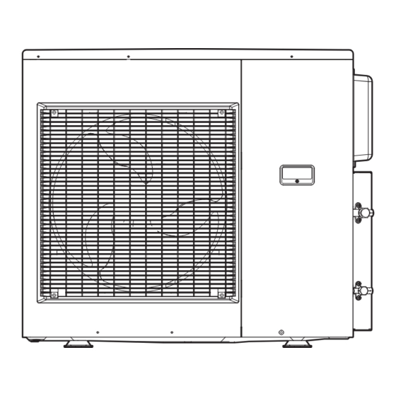
Page 4: External Dimension
AE-X4M30PU EXTERNAL DIMENSION 5.9 (150) 23.2 (590) 5.9 (150) Length unit : inch (mm) 3 (75) 2 (51.3) 0.6 (16) 37 (941) 35 (890) 1.3 (32.7) 12.6 (320) 37 (940) -
Page 5: Capacity Table
AE-X4M30PU CAPACITY TABLE COOLING CAPACITY TABLE Indoor unit Running curent (A) Operating Cooling capacity (Btu/h) Power input (W) combination Rating (Min. - Max.) Status Rating (Min. - Max.) Rating ( Min - Max) 208V 230V 18 12 11,864 7,909 4,614... - Page 6 AE-X4M30PU Indoor unit Running curent (A) Operating Power input (W) Cooling capacity (Btu/h) combination Rating (Min. - Max.) Status Rating (Min. - Max.) Rating ( Min - Max) 208V 230V 18 18 14,500 14,500 29,000 (11,500 - 30,200) 3,080 (630 - 3,480) 15.1 (3.6 - 16.9)
- Page 7 AE-X4M30PU Indoor unit Running curent (A) Operating Heating capacity (Btu/h) Power input (W) combination Rating (Min. - Max.) Status Rating (Min. - Max.) Rating ( Min - Max) 208V 230V 18 18 13,200 13,200 6,600 33,000 (12,000 - 37,000) 2,780 (800 - 3,250) 13.6 (4.1 - 15.8)
-
Page 8: Electrical Parts
AE-X4M30PU ELECTRICAL PARTS Fuse 1, 5 — QFS-GA065JBZZ(20A,250V) Fuse 2 — QFS-GA062JBZZ(3.15A,250V) Fuse 3, 6 — QFS-GA063JBZZ(2A,250V) CYCLE PARTS PARTS MODEL TYPE PARTS CODE Compressor SNB172EFKMT 17.2cc DC TWIN ROTARY 1200W PCMPRA718JBEZ Fan motor ARW8404SH DC MOTOR 8Poles, 60W CMOTLB541JBEZ Φ1.8... - Page 9 AE-X4M30PU from PFCM PWB from Pressure from Terminal Board to Filter PWB CN14 AC1 (Black) from Terminal Board Switch Unit D "2", Unit C "2", Unit B "2", Unit A "2", "L1" Power Supply (Black) (To CN14) (PRESSURE SWITCH) (THERMAL FUSE)
- Page 10 AE-X4M30PU from Terminal Board AB (L2) from Main PWB (T14)(Blue) from Terminal Board AB (L1) (Blue) from Terminal Board (L1)(Blue) (Brown) BT22 BT23 (BROWN) (BLUE) from Terminal Board (FROM TERMINAL BOARD (FROM TERMINAL BOARD (BLUE) INDOOR UNIT 1) INDOOR UNIT N)
- Page 11 AE-X4M30PU...
-
Page 12: Explanation Of Circuit And Operation
AE-X4M30PU EXPLANATION OF CIRCUIT AND OPERATION BLOCK DIAGRAM 20 A Fuse Fuse PFCM Power supply Smoothing Filter AC power module circuit circuit circuit CPU oscillator circuit DC power supply circuit DC over voltage detection circuit Expansion valve A drive circuit... -
Page 13: Functions
AE-X4M30PU FUNCTIONS 1. FREQUENCY CONTROL 1) AC current peak control Cooling mode Heating mode 17.6A 18.4A 2) Prevention control of outdoor heat exchanger overheating If the temperature of the outdoor heat exchanger exceeds the overheating prevention line 1or 2 during cooling, the operating frequency is lowered by approximately 5 to 15Hz. - Page 14 AE-X4M30PU 5. SERIAL SIGNALS Serial signals consist of all 96-bit signals. If the condition as outdoor unit unable to receive a serial signal from the indoor unit continues for 30 seconds, it closes the expansion valve which corresponds to the room which can not be communicated. If all indoor units can not communicate with the outdoor unit, the compressor is stopped.
- Page 15 AE-X4M30PU 3) During defrosting When defrosting begins, the compressor stops. Approximately 1 minutes later, the compressor reactivates in the refrigeration cycle, and the outdoor heat exchanger is defrosted. Each mode is as follows: The outdoor fan is s topped. The operating frequency is as shown in the table below.
-
Page 16: Trouble Shooting Guide
AE-X4M30PU TROUBLE SHOOTING GUIDE SELF-DIAGNOSIS FUNCTION NOTE: WHEN TURN ON THE POWER SUPPLY AGAIN, WAIT MORE THAN 10 MINUTES AFTER TURN OFF TO PRE- VENT ELECTRIC SHOCK. Indoor unit • To display the self-diagnosis, hold down the AUX button for over 5 seconds on the indoor unit when the indoor unit is not operating. - Page 17 AE-X4M30PU <INDOOR UNIT> ○:1-second ON / 1-second OFF Malfunction Outdoor unit Indoor unit Content of diagnosis Problem No.* indication Check point Action symptom → (LED1) Lamp Main Sub Main Normal Normal O O O O O Timer (Orange) Normal condition...
- Page 18 AE-X4M30PU Malfunction Outdoor unit Indoor unit Content of diagnosis Problem No.* indication Check point Action symptom → (LED1) Lamp Main Sub Main Indoor and 6-time O O O O O Timer (Orange) Outdoor unit DC over current Go to “DC Over Current Error (6-0 error)”.
- Page 19 AE-X4M30PU Malfunction Outdoor unit Indoor unit Content of diagnosis Problem No.* indication Check point Action symptom → (LED1) Lamp Main Sub Main Indoor and 12-time O O O O O Timer (Orange) Thermal fuse Thermal fuse error 1) Check the thermal fuse in...
- Page 20 AE-X4M30PU *Remark The malfunction No. is calculated using the following way. Example) →Lamp Calculation Main Indoor unit lamp 16 8 Timer (orange) O O O O O Operation (green) 4+1=5 Plasmacluster (blue) Figure 1 Temperature properties of indoor thermistors Ω...
- Page 21 AE-X4M30PU Figure 2 Temperature properties of outdoor thermistors TH1 : Compressor thermistor (CN8A 1 - 2 ) TH2 : Heat exchanger pipe thermistor (CN8A 3 - 4 ) TH3 : Outdoor temp. thermistor (CN8A 5 - 6 ) TH4 : Suction thermistor (CN8A 7 - 8 )
- Page 22 AE-X4M30PU...
- Page 23 AE-X4M30PU 2) When one room is not cooled (other rooms are cooled) Is the timer lamp of the indoor unit in the room not cooled flashing ? Press the OPERATION button to start operating the air-conditioner. 61ºF(16ºC)) (Set the cooling mode to...
- Page 24 AE-X4M30PU 3) When all rooms are not heated Does the air get cooler in the cooling operation mode? Press the ON switch on the remote Refer to 1 All rooms are control to run the air conditioner. not cooled. Set the temperature to 86ºF(30ºC) in the heating mode and start operation.
-
Page 25: Protective Functions And Operations
AE-X4M30PU PROTECTIVE FUNCTIONS AND OPERATIONS Operation Function Description Detection time Restart condition Compressor is stopped if a current approxi- During compressor Automatically restarts after mately 25A or more flows in the power transistor DC over current 4 times operation safety time (180 seconds) module. -
Page 26: Refrigeration Cycle
Expansion valve B Heat exchanger UNIT A Expansion valve A Heat exchanger STOP valve (Gas) INDOOR UNIT OUTDOOR UNIT (AE-X4M30PU) * 15K, 18K can’t be connected. 2. Flow of refrigerant UNIT D * UNIT C * UNIT B UNIT A... - Page 27 AE-X4M30PU 3. Cycle temperature and pressure in stop valve Operation Mode Running unit Cool (Max) Cool (Test run) Heat (Max) Heat (Test run) 186 ºF (85℃ ) 156 ºF (69℃ ) 158 ºF (70℃ ) 112 ºF (44℃ ) 103 ºF (40℃ ) 100 ºF (38℃...
-
Page 28: Performance Curves
AE-X4M30PU 4. PERFORMANCE CURVES NOTE: Total Capacity and total input with 4 units (9k+7k+7k+7k) running. At Heating At Cooling (Running frequency: 90HZ) (Running frequency: 108HZ) 4000 3200 3500 3000 3000 2800 2500 2600 2400 2000 (ºF) (ºF) 95 100 105 110 115 120 (ºC) -
Page 29: Disassembling Procedure
AE-X4M30PU DISASSEMBLING PROCEDURE PROCEDURE 1. Remove the five (5) screws fixing the front panel R. 4. Remove the one (1) screw fixing the cable cover. 2. Remove the ten (10) screws fixing the top cover. 5. Remove the six (6) screws fixing the front panel L. - Page 30 AE-X4M30PU 7. Remove the eleven (11) screws fixing the side cabinet R. 11. Disconnect the nine (9) connectors. 12. Remove the two (2) compressor covers. 8. Cut the insulators. (2 points) Compressor 9. Remove the two (2) screws fixing the control box cover.
- Page 31 AE-X4M30PU 15. Remove the five (5) screws fixing the control box assembly. 18. Cut the two (2) fixing bands. 16. Remove the one (1) nut fixing the propeller fan. 19. Remove the four (4) screws fixing the fan motor. 17. Remove the two (2) screws fixing the motor angle.
-
Page 32: Position Of The Thermistors
AE-X4M30PU Position of the thermistors. Green Green Yellow Brown White Orange Orange Blue Black... -
Page 33: How To Disassemble The Control Box Assembly
AE-X4M30PU How to disassemble the control box assembly 4. Remove the 2 screws fixing the FILTER PWB. 1. Remove the 3 screws fixing the PFC PWB. 5. Unlock the 2 spacer’s lock. 2. Remove the 4 screws fixing the MAIN PWB. - Page 34 AE-X4M30PU...
-
Page 35: Parts List
AEX4M30PU PartsGuide PARTS LIST MULTI SPLIT TYPE ROOM AIR CONDITIONER OUTDOOR UNIT AE-X4M30PU MODEL CONTENTS OUTDOOR UNIT PARTS 1 PACKING PARTS OUTDOOR UNIT PARTS 2 INDEX OTHER OUTDOOR PARTS Parts marked with " " are important for maintaining the safety of the set. Be sure to replace these parts with specified ones for maintaining the safety and performance of the set. - Page 36 AEX4M30PU [1] OUTDOOR UNIT PARTS 1 2-37 2-40 2-23 2-28 1-44 2-49 1-48 2-24 2-20 2-26 4-10 2-25 4-11 1-60 1-12 1-36 4-11 2-31 2-39 1-44 1-66 1-52 4-13 1-76 1-66 2-17 4-35 1-69 3-15 1-49 2-41 1-11 1-61 2-21 1-61 2-22 1-5-2...
- Page 37 AEX4M30PU PRICE PART PARTS CODE DESCRIPTION RANK MARK RANK [1] OUTDOOR UNIT PARTS 1 Fan motor CMOTLB541JBEZ Terminal board angle LANG-A769JBWZ Cord holder LHLD-A539JBFA Cord clamp holder LHLD-B095JBFA 1-5-1 Terminal board QTANZA093JBZZ 1-5-2 Terminal board QTANZA096JBZZ 1-11 Control box assembly DBOX-A044JBWZ 1-12 Control board unit...
- Page 38 AEX4M30PU PRICE PART PARTS CODE DESCRIPTION RANK MARK RANK [1] OUTDOOR UNIT PARTS 1 4-34 Special Washer LHLD-B067JBEZ 4-35 Special Screw LX-BZA075JBE0 [2] OUTDOOR UNIT PARTS 2 1-79 1-73 3-14 3-21 1-54 3-10 6-12 3-12 1-73 1-73 3-13 6-11 3-33 3-31 3-38 3-34...
- Page 39 AEX4M30PU PRICE PART PARTS CODE DESCRIPTION RANK MARK RANK [2] OUTDOOR UNIT PARTS 2 1-54 Compressor cord QW-IZA161JBZZ 1-73 Thermistor RH-HXA182JBZZ 1-78 Thermistor RH-HXA183JBZZ 1-79 Thermistor spring MSPR-A036JBE0 2-16 Flare coupling base PDAI-A298JBTA 2-29 Flare cou. Sub-L LSUB-A021JBWZ 2-30 Flare cou. Sub-S LSUB-A020JBWZ 2-63 Unit label...
- Page 40 AEX4M30PU PRICE PART PARTS CODE DESCRIPTION RANK MARK RANK [3] OTHER OUTDOOR PARTS 1-40 Pressure switch RBIM-A003JBEZ 1-41 PFC Coil RTRN-A306JBZZ 4-19 Heat sink holder Sub LHLD-B237JBFZ 4-21 Holder cover PCOV-C027JBWZ 4-26 Label (Terminal CDP) TLAB-F836JBRZ 4-27 TLAB-F685JBRZ Label (Terminal AB) 4-29 Label TLAB-F689JBRZ...
- Page 41 AEX4M30PU INDEX PRICE PART PRICE PART PARTS CODE PARTS CODE RANK MARK RANK RANK MARK RANK NFANPA152JBEZ 1-2-36 [ C ] CCHS-B381JBTA 1-2-14 [ P ] CCIL-A185JBKZ 2-3-8 PACU-A054JBEZ 2-3-10 CMOTLB541JBEZ 1-1-1 PCAP-A083JBEZ 2-3-33 CPADBA072JBKZ 4-5-1 PCAP-A084JBEZ 2-3-34 CPADBA073JBKZ 4-5-2 PCAP-A103JBEZ 2-3-40 CPIPCB666JBKZ...
- Page 42 AEX4M30PU PRICE PART PARTS CODE RANK MARK RANK RFIL-A064JBE0 3-1-6 RH-HXA182JBZZ 1-1-69 " 2-1-73 RH-HXA183JBZZ 2-1-78 RMOTSA050JBZZ 2-3-17 RNF--A001VBE0 3-1-7 RTRN-A306JBZZ 3-1-41 [ S ] SPADBA707JBEZ 4-5-4 SPAKCE269JBEZ 4-5-3 [ T ] TINS-B434JBRZ 2-6-1 TLABCE011JBRZ 1-2-53 TLAB-F685JBRZ 3-4-27 TLAB-F686JBRZ 1-2-60 TLAB-F689JBRZ 3-4-29 TLAB-F690JBRA...
Need help?
Do you have a question about the AE-X4M30PU and is the answer not in the manual?
Questions and answers