
Related Manuals for Digimerge DND7220


Summary of Contents for Digimerge DND7220
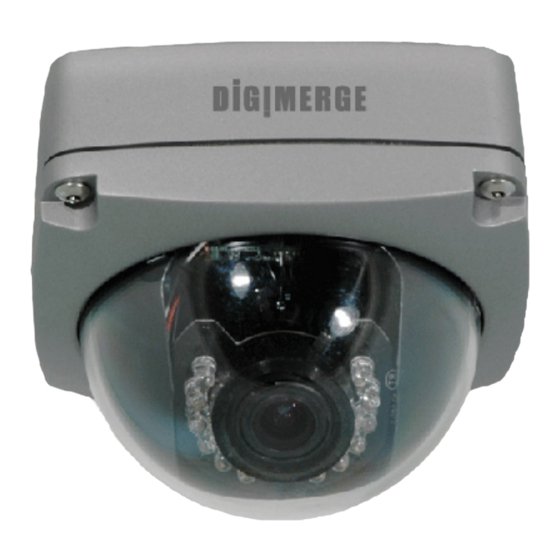
- Page 1 HARDWARE MANUAL English version 1.0 DND7220 Series DND7220 Networkable Camera © Copyright 2007 Digimerge Technologies Inc.
- Page 2 It’s small size and advanced performance features, including 30ft. (10m) IR illumination range and Varifocal lens, put the DND7220 in a class by itself. With advanced features, such as auto detect, dual-codec, power over ethernet and compatibility with a variety of video management software platforms, the DND7220 takes network performance to a whole new level.
- Page 3 Important Safeguards Important Safeguards In addition to the careful attention devoted to quality standards in the manufacture process of your video product, safety is a major factor in the design of every instrument. However, safety is your responsibility too. This sheet lists important information that will help to assure your enjoyment and proper use of the video product and accessory equipment.
- Page 4 18. Heat - The product should be situated away from heat sources such as radiators, heat registers, stoves, or other products (including amplifiers) that produce heat. © HARDWARE MANUAL | Copyright 2007 Digimerge Technologies Inc.
- Page 5 4. Keep enough space around the unit for ventilation. Slots and openings in the storage cabinet should not be blocked 5. During lightning storms, or when the unit is not used for a long time, disconnect the power supply, antenna, and cables to protect the unit from electrical surge DIGIMERGE TECHNOLOGIES INC. http://www.digimerge.com Revision 1.0...
- Page 6 DND7220 Camera Features SECTION 1 DND7220 Camera Features Technology • High Resolution Sony Super HAD 1/3” CCD (540TVL) • Hybrid Technology Allows for Integration into IP Networks as well as Traditional Analogue Surveillance Systems • MPEG4 / MJPEG Dual Codec •...
-
Page 7: Table Of Contents
Section 1 - GETTING STARTED ............9~10 Package Contents ................. 10 Section 2 - PRODUCT OVERVIEW ..........11~14 DND7220 - Cable Connections ............ 12 DND7220 - Camera Lens Adjustments ......... 13 Section 3 - INSTALLATION ............. 15~20 Installation Overview ..............16~20 Installing the Base ......................16 Adjusting the Lens ...................... - Page 8 Menu - Edit Network Parameters .................. 37 Appendix #4 - Power Over Ethernet (PoE) ......38~39 Appendix #5 - Hardware Reset ..........40~41 DigiViewer Reset ......................40 Hardware Reset ...................... 40~41 Digimerge IP Products..............42 Digimerge Warranty ..............43~44 © HARDWARE MANUAL | Copyright...
-
Page 9: Section 1 - Getting Started
SECTION 1 GETTING STARTED Package Contents......10... -
Page 10: Package Contents
12V DC Power Adaptor 2 x Allen Keys for Security Software CD & Quick Screws Installation Guide CHECK YOUR PACKAGE TO CONFIRM THAT YOU HAVE RECEIVED THE COMPLETE SYSTEM, INCLUDING ALL COMPONENTS SHOWN ABOVE. © HARDWARE MANUAL | Copyright 2007 Digimerge Technologies Inc. -
Page 11: Section 2 - Product Overview
SECTION 2 PRODUCT OVERVIEW DND7220 - Cables......12 DND7220 - Camera Lens....13... -
Page 12: Dnd7220 - Cable Connections
DND7220 - Cable Connections SECTION 2 DND7220 - Cable Connections All Camera Connections are available on the external Cable. 1. ETHERNET PORT / PWR / NET LED INDICATORS - Connect an Ethernet Cable to the RJ-45 Ethernet port to connect the Camera to the network. -
Page 13: Dnd7220 - Camera Lens Adjustments
DND7220 - Camera Lens SECTION 2 DND7220 - Camera Lens Adjustments The Camera Lens can be adjusted when the camera Dome Cover is removed. 1. FOCUS CONTROL - Use a screwdriver to focus the lens of the Camera. 2. ZOOM CONTROL - Use a screwdriver to set the focus on the Camera. -
Page 15: Section 3 - Installation
SECTION 3 INSTALLATION Installing the Base .......16 Adjusting the Lens ......17 Connecting the Cables ....18~19 Software Installation Overview ....20... -
Page 16: Installation Overview
Place the rubber washer onto the screw (both provided with the Hardware Pack). Repeat for all screws. iv. Use a screwdriver to install the 4 screws through the holes in the base into the mounting surface. © HARDWARE MANUAL | Copyright 2007 Digimerge Technologies Inc. -
Page 17: Adjusting The Lens
Installation Overview SECTION 3 B. Adjusting the Lens NOTE: The lens should be adjusted prior to reattaching the camera cover. If you are adjusting the Camera using a direct connection to a PC, you will need to use a Crossover Ethernet Cable, or use the BNC Analogue Output. -
Page 18: Connecting The Cables
3. Audio: Connect an RCA Cable to the audio port on a CCTV Monitor or DVR (when using a BNC Video Connection) to listen to Audio from the camera. This is an optional connection. © HARDWARE MANUAL | Copyright 2007 Digimerge Technologies Inc. - Page 19 Installation Overview SECTION 3 4. Alarm Block: The Camera Alarm Block can be used to send or receive a signal from a compatible DVR or CCTV System. Please consult the manual for the device you wish to connect to the camera for details. i.
-
Page 20: Software Installation Overview
SECTION 3 Software Installation Overview This IP device is provided with software applications to make the most of the Device. This includes software for installing, configuring and managing 1 or more Digimerge IP Devices. The following applications are included: •... -
Page 21: Section 4 - Network Connectivity
SECTION 4 NETWORK CONNECTIVITY Network Connectivity Overview ...22 Locating the MAC and IP Address ..23 Router Port Forwarding .......24 Setting Up Your DDNS Account .25~26 DigiViewer DDNS Setup .....27 Remote Access with IE....28~29... -
Page 22: Network Connectivity Overview
DigiViewer to allow DDNS connectivity. See the DigiConsole / DigiViewer Software Guide (provided with this Camera) for installation requirements and details on using the software. CAMERA INTERNET ROUTER (Not Included) (Not Included) © HARDWARE MANUAL | Copyright 2007 Digimerge Technologies Inc. -
Page 23: Locating The Mac And Ip Address
Select the Find Devices button. 2. The DigiConsole automatically locates all available Digimerge IP devices on the network, and displays a snapshot of the results. Click on any available device to display a snapshot image on the right side screen display. -
Page 24: Router Port Forwarding
To locate your external IP address, visit http://www.whatismyip.com NOTE: If using multiple IP Devices on the same network, each device will need to be assigned to a different remote access port. © HARDWARE MANUAL | Copyright 2007 Digimerge Technologies Inc. -
Page 25: Setting Up Your Ddns Account
Setting Up Your DDNS Account Digimerge offers a free DDNS server for use with your IP Camera. A DDNS account allows you to set up a web site address that points back to your Local Network. The following outlines how to set up your free DNS account. -
Page 26: Setting Up Your Ddns Account
Domain Name: _______________________________________________ User Name: _________________________________________________ Password: __________________________________________________ NOTE: The information sent to you in E-mail is CASE SENSITIVE. It is important when set- ting up your DDNS information on your device. © HARDWARE MANUAL | Copyright 2007 Digimerge Technologies Inc. -
Page 27: Digiviewer Ddns Setup
B. Click on the NETWORK SERVICES link. C. Enter the DDNS information received in the DDNS Confirmation Email: Check ‘Enable Digimerge Dynamic DNS Service Enter the DDNS Domain name you chose during the DDNS Registration process Enter the Account Name you setup during the DDNS Registration Process. -
Page 28: Remote Access With Internet Explorer
Remote Access with Internet Explorer Open Internet Explorer, and enter the Local IP (i.e. http://192.168.0.104 if inside the Local Network), the Remote IP (i.e. http://72.154.89.164) or DDNS Address (http:// myurl.digimerge.net) for the remote IP Device. http://myurl.digimerge.net Internet Explorer Security Warnings Several security warnings may appear (based on your Internet Explorer settings). -
Page 29: Internet Explorer Security Warnings - Program Installation
• Click the Install button to allow the ActiveX controls to be setup on the PC. Internet Explorer Security Warnings - Windows Firewall The Digimerge IP Devices require connectivity across the network, and may be flagged by the Windows Firewall when a connection to your PC is made. -
Page 31: Section 5 - Appendices
APPENDICES Appendix #1 - Camera Specifications Appendix #2 - COM / GPIO Terminal Block Appendix #3 - Changing the Camera Appendix #4 - Power Over Ethernet (PoE) Appendix #5 - Hardware Reset Other Digimerge IP Products Digimerge Limited Warranty... -
Page 32: Appendix #1 - Camera Specifications
16K~4M bits/sec (CBR/VBR configurable high quality VBR settings for MJPEG can reach up to 10 Mbps)) Day / Night Function • 12 High Intensity 850nm IR LEDs providing up to 30ft. range • IR Cut Filter © HARDWARE MANUAL | Copyright 2007 Digimerge Technologies Inc. -
Page 33: Network
Appendix #1 - Camera Specifications SECTION 5 Network Network Interface: Network • 10/100 Base-T Ethernet Protocols: • TCP (UDP)/IP, IMCP, HTTP, FTP, SMTP, DHCP, NTP, DNS, DDNS, RTSP, RTP/TCP (UDP). Management Event Management • Triggers: Motion Detection • Manual Recording Installation DigiConsole Utility (PC) Firmware Upgrade... -
Page 34: Appendix #2 - Changing The Cable Position
Base. Leave the Bolt on the Cable. 3. Use the small hex tool (included in the Hardware Pack) to remove the holding screw from the Camera Base Unscrew and remove the Cable Nut. © HARDWARE MANUAL | Copyright 2007 Digimerge Technologies Inc. - Page 35 Appendix #2 - Changing the Cable Position SECTION 5 4. Set aside the following: • Cable Nut • Plug Screw • Small Hex Key • Holding Screw 5. Screw the Plug Screw to the side of the Camera Base. Screw the Cable Nut into the bottom of the Camera Base.
-
Page 36: Port Diagram - Circuit Board
Blue / White Brown / White Brown J3 Port - Cable Order: (Oriented Top~Bottom) White Black White Yellow Black J10 Port - Cable Order: (Oriented Left~Right) Black Black Black Green Black. © HARDWARE MANUAL | Copyright 2007 Digimerge Technologies Inc. -
Page 37: Appendix #3 - Changing The Camera Network Settings
Appendix #3 - Changing the Camera Network SECTION 5 Appendix #3 - Changing the Camera Network Settings The network settings on the camera can be manually set using the DigiConsole application: Menu - Edit Network Parameters The Edit Network Parameters option allows the user to manually set the Network Device options (if desired). -
Page 38: Appendix #4 - Power Over Ethernet (Poe)
• Locate device where it truly needs to be located (Not constrained by the location of an AC outlet) Centralize vs. Localize Power Source • Allow use of a centralized UPS (Uninterruptible power supply) to guarantee power to the device even during a power failure © HARDWARE MANUAL | Copyright 2007 Digimerge Technologies Inc. -
Page 39: Appendix #4 - Power Over Ethernet (Poe)
Poe Injector + Splitter ⇒ ⇒ ⇒ Non-PoE Ethernet Switch PoE Injector Active Splitter IP Camera (non-PoE) Digimerge IP Devices are certified for use with Microsemi PoE hardware solutions. Visit www.microsemi.com/PowerDsine for details on all available PoE hardware solutions. Revision 1.0... -
Page 40: Appendix #5 - Hardware Reset
1. Unplug the power adaptor from the Power Cable port. 2. Locate the RESET BUTTON. The button is located on the lower board, beneath the J4 port, and is visible on the side of the board. © HARDWARE MANUAL | Copyright 2007 Digimerge Technologies Inc. - Page 41 Appendix #5 - Hardware Reset SECTION 5 3. Use the small hex tool to press in this button - you will hear an audible ‘click’ noise. Keep pressing the Reset button. 4. Reconnect the Power Adaptor. Continue holding the Reset Button. 5.
-
Page 42: Digimerge Ip Products
Digimerge IP Products SECTION 5 Digimerge IP Products © HARDWARE MANUAL | Copyright 2007 Digimerge Technologies Inc. -
Page 43: Digimerge Warranty
Digimerge, be repaired or replaced with equal or better product in terms of hard- ware features without charge if all the conditions set forth in this document are met. - Page 44 No claims or statements regarding the product, whether written or verbal, by salespeople, retailers, dealers or distribu- tors, that are not contained in this limited warranty or in the owner's manual are authorized by Digimerge and do not modify or expand this warranty. Some countries, states, or provinces do not allow the exclusion or limitation of implied warranties or the limitation of incidental or consequential damages for certain products supplied to consumers or the limitation of liability for personal injury.
- Page 45 It’s all on the web Product Information Specification Sheets User Manuals Software Upgrades Quick Start Guides Firmware Upgrades VISIT www.digimerge.com www.digimerge.com Digimerge Technologies Inc.
Need help?
Do you have a question about the DND7220 and is the answer not in the manual?
Questions and answers