
Related Manuals for klover pellet boiler 24


Summary of Contents for klover pellet boiler 24
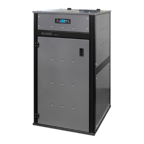
- Page 1 Pellet boiler PELLET BOILER 24 INSTALLATION USE AND MAINTENANCE USEFUL ADVICE User guide...
- Page 3 We would like to thank you again for trusting KLOVER products and we also inform you that these models are the result of forty years experience in the field of construction of solid fuel products which uses water as heat carrying fluid.
-
Page 5: Table Of Contents
GENERAL INDEX Introduction…………………………………………………………………………………….. 6 Important safety instructions……………………………………………………………………. 6 Some precautions……………………………………………………………………………….. 6 Conventions used in the manual……………………………………………………………….. 6 Destination of use………………………………………………………………………………... 7 Installation regulations………………………………………………………………………….. 7 Health and safety………………………………………………………………………………… 7 The machine and the pellets………………………………………………………………… 8 Boiler components………………………………………………………………………………. 8 Connections data sheet…………………………………………………………………………. 10 Technical features……………….………………………………………………………………. -
Page 6: Introduction
Safety Standards in force. They will be responsible for the definitive installation of the machinery and its consequent proper operation. KLOVER srl will not be held responsible if these precautions are not respected. During installation of the appliance all local regulations, included those referring to National and European Standards, must be followed. -
Page 7: Destination Of Use
Approved Document J. Health and Safety Care must be taken when installing a Klover pellet stove to ensure that the requirements of the Health and Safety at Work Act are met. Handling Adequate facilities must be available for loading, unloading and site handling the appliance bearing in mind the weight of the appliance. -
Page 8: The Machine And The Pellets
THE MACHINE AND THE PELLETS Boiler components The boiler is delivered with the following equipment: USE, INSTALLATION AND MAINTENANCE GUIDE; 1 POWER SUPPLY CABLE; 1 METAL KEY FOR VENT VALVE; 1 RUBBER PIPE FOR VENT VALVE; ... - Page 9 MASTER SWITCH RETURN CONNECTION ATTACHMENT FOR POWER WITH SAFETY VALVE SUPPLY CABLE CALIBRATED AT 2.5 BAR AND 2 INCORPORATED FUSES ROOM (4A 250V) INTAKE DOMESTIC HOT THERMOSTAT FLUE PIPE WATER OUTLET CONNECTION EXHAUST (ONLY ON MOD. CLAMP WITH SET-UP) FLOW SECURITY SYSTEM DRAIN CONNECTION...
-
Page 10: Connections Data Sheet
Connections data sheet REAR VISTA POSTERIORE VIEW M = Ø ¾” F GAS SYSTEM FLOW R = Ø ¾” M GAS SYSTEM RETURN C = Ø 14 mm DOMESTIC HOT WATER OUTLET (on prepared models only) F = Ø 14 mm DOMESTIC COLD WATER INLET S = Ø... -
Page 11: Technical Features
Technical features 20,9 (6,5) Total heat output (minimum) Water heat output (minimum) 17,6 (5,2) 84,6 (80) Efficency (minimum) Carbon monoxide [at 10% O ] (minimum) 0,012 (0,146) Nominal voltage Nominal frequency Maximum power requirement (in stand-by) 310 (2) Power requirement (minimum) 98 (70) Expansion vessel l/preloading bar 8 / 1... -
Page 12: Pellet Features
Pellet features The boiler has been tested with all types of pellets present on the market. The pellet used must have the following features: Diameter 6 mm; Maximum length 35 mm; Maximum humidity content 8 – 9 %; ... -
Page 13: Requisites Of The Place Of Installation
REQUISITES OF THE PLACE OF INSTALLATION Positioning The initial phase for the best installation of the boiler is to determine its optimal location; the following data needs to be considered for this: An external air vent can be made; ... -
Page 14: Flue And Connection To The Same - Chimney
If it is not possible to realise the air vent in the wall behind the boiler, make the hole in a perimeter wall where the boiler is installed. If it not possible to realise the external air vent in the same room where the boiler is installed, this hole can be made in an adjoining room as long as this room communicates permanently, by means of a transit hole (15 cm minimum diameter). - Page 15 Preferably circular internal section: squared and rectangular sections must have rounded angles with radius larger than 20 mm; Constant, free and independent internal section; Rectangular sections with 1.5 maximum ratio between the sides; If the flue is installed externally or in a cold room (e.g. boiler room) it is absolutely necessary that it is insulated to avoid the flue gas cooling and condensate forming;...
- Page 16 FURTHER SPECIFICATIONS TO BE CONSIDERED The boiler functions with the combustion chamber in depression; it is fundamental that the exhaust is hermetically sealed. It is recommended to use rigid stainless steel pipes, with sealing gaskets, with diameter of 120 mm. The pipes must have a double wall or be suitably insulated with rock wool.
-
Page 17: Electric Connections
During the final wiring of the circuit, only use components with a suitable electric protection rating. KLOVER srl declines all responsibility for injury to persons, animals or damage to objects deriving from failure to connect the boiler to earth and failure to comply with IEC Standards. -
Page 18: Connection To Room Thermostat
Below find a connection example using a 3-way valve with spring return. Remember that the hydraulic connection must be made in a way that when the valve is at rest, the water passes from the gas boiler. Only when the pellet boiler temperature is sufficient (value set from control panel), the 3- way valve is powered and therefore closes the gas boiler circuit and opens the Pellet Boiler circuit. -
Page 19: Hydraulic Connection
HYDRAULIC CONNECTION The hydraulic connections must be made in a rational way using the connections on the boiler template. To ease connection of the pipes, we have prepared all hydraulic connections on the rear, leaving space to make the connections easily. The boiler can be coupled to any other boiler already installed in the system;... -
Page 20: Connection Examples
CONNECTION EXAMPLE WITH DOMESTIC HOT WATER STORAGE COUPLING These diagrams are purely indicative and do not imply any commitment or responsibility by KLOVER s.r.l. or by its partners. The executive designing and the consequent activation must be carried out according to the regulations in force. -
Page 21: Cleaning And Maintenance
CLEANING AND MAINTENANCE Precautions before cleaning Before carrying out any cleaning or maintenance, make sure that: The boiler is off and has cooled down completely; The ash is completely cold; Before re-starting the boiler, re-install all previously disassembled components. During the cleaning operations, use the individual protection devices envisioned by the 89/391/EEC Directive. -
Page 22: Extraordinary Cleaning
Empty the ash drawer. ATTENTION: use suitable “bin” type vacuum cleaners, with fine mesh filter, in order to prevent part of the ash from being spilled back out into the environment and damage the suction device itself. Extraordinary cleaning To be performed at least every 30 days. Carry out routine cleaning;... - Page 23 Remove the 4 flue deflectors (2 on the right and 2 on the left) from the sides of the combustion chamber and, by means of a spatula, scrape the inner wall surfaces and then suck up any possible deposit.
- Page 24 After removing the 4 flue deflectors, clean the flue (both right and left) next to the pipes which are above the combustion chamber, using the supplied brush. Once you have cleaned, re-fit the 4 flue deflectors. After having removed the ash drawer, extract the underlying base.
- Page 25 Do not force the flue gas intake device flaps with the ash vacuum hose. Use a suitable suction device to remove the internal deposits and then re-position the base and the ash drawer. For correct functioning, it is necessary to use a suction device to remove the sawdust deposit on the base of the tank at least every 15 days.
-
Page 26: Cleaning The Ceramic Glass
Cleaning the ceramic glass Always clean the glass when the boiler is off and completely cold. Use a damp cloth and specific detergent for ceramic glasses. Do not use abrasive sponges. Cleaning the flue This operation must be performed at least twice a year, at the beginning and half way through the winter season, and however when necessary. -
Page 27: The Display
THE DISPLAY The equipment's functioning state is displayed by the console. Many types of displays and the available settings based on the selected menu can be made by accessing the menu. The following figure shows the display in equipment on or off conditions. CLOCK ROOM TEMPERATURE (optional) 17:19... - Page 28 Meaning of the state signals is found top-right of display (2nd LED SERIES). 1 – the LED is on when the chrono-thermostat's daily program is active. 2 – the LED is on when the chrono-thermostat's weekly program is active. 3 – the LED is on when the chrono-thermostat's week-end program is active. 4 –...
- Page 29 Accesses the selected menu. Accesses the subsequent sub-menu In menu.. level. Ignites and/or switches off boiler when Working.. pressed for 2 seconds. ON/OFF In alarm block.. Releases alarm. Outlet Goes to upper menu level memorising In menu/programming.. the made modifications. Decreases DHW thermostat Working/off..
-
Page 30: The Menu
THE MENU Access the Menu by pressing key 3 (Set). This is divided into different entries and levels to access the board's programming and settings. The menus to be modified scroll using keys 5 and 6. The individual menus are modified using keys 1 and 2. The technical programming access menu entries (parameters reserved to Technical Assistance Centre) are protected by access key. - Page 31 PROGRAM 3 MENU LEVEL SELECTION MEANING POSSIBLE VALUES 02 – 03 – 20 Time – OFF START PROG 3 Ignition time 02 – 03 – 21 Time – OFF STOP PROG 3 Switch-off time 02 – 03 – 22 MONDAY PROG 3 On/off 02 –...
- Page 32 In this case, the boiler firstly enters functioning economy and then automatically switches off when room temperature (detected with KLOVER remote control) is satisfied..if wanting to control boiler with KLOVER remote control room temperature and with boiler thermostat, I must: ...
- Page 33 Summary: REMOTE CONTROL ROOM THERMOSTAT CASE ACTION ROOM PROBE CONTACT Works with room thermostat contact Works with room thermostat contact Works with remote control room probe only Works with remote control room probe and room thermostat contact 5. Menu 05 – 3-Way Valve Threshold Allows setting temperature threshold for switch-over of 3-Way motorised valve installed in DHW system.
-
Page 34: Commissioning
COMMISSIONING Filling the system for the first time After having connected the boiler, fill the system as follows: Check pipe sealing of both the expansion vessel and the circulation pump; Open “air vent valve” of boiler using the relevant key (see “Boiler components”);... -
Page 35: Boiler Work Phase
Summary: The ignition cycle can last max 25 minutes and is divided into four phases: 1 - START Flue gas intake device ignition duration 40 seconds 2 - P-LOAD PELLET Pellet pre-load (initial continuous load) and resistance ignition Pr40 = pre-load time in ignition 3 - FLAME STAND-BY pellet load (intermittent load) and functioning resistance Pr01 –... -
Page 36: Producing Domestic Hot Water (Prepared Models Only)
Producing domestic hot water (prepared models only) The domestic hot water is produced instantly via a double heat exchanger immersed in the water inside the boiler. Therefore, the boiler must be at temperature (60°C at least) to have domestic hot water. Set boiler in DHW power “DHW”... -
Page 37: Alarms Signal
- Room Temperature Press key 2 to select “SET ROOM TEMP” mode to modify room temperature. Press keys 1 and 2. The display appears as in figure below during this operation 25° SET ROOM TEMP Press key 4 or wait a few seconds to confirm the wanted value setting. ATTENTION: The room thermostat temperature is taken into account if the remote control to be applied to (also see ”Menu 04”... -
Page 38: What Happens If
WHAT HAPPENS IF.. …the pellet does not ignite With no ignition. The “NO IGNIT-“ alarm message appears. Cancel the alarm and bring the boiler to standard condition by pressing key 4 for a few seconds..the fire door is open or closed improperly In case the door is open or closed improperly, the motor reducer cannot be powered electrically, not allowing the boiler to switch on. -
Page 39: Circuit Board Parameters
THE PARAMETERS GIVEN BELOW ARE ALREADY MEMORISED IN THE BOILER INSPECTION PHASE DIRECTLY IN THE FACTORY. THESE PARAMETERS ARE THE RESULT OF CAREFUL TESTS WITH VARIOUS TYPES OF PELLETS AND MUST NOT BE CHANGED WITHOUT THE AUTHORISATION OF KLOVER srl, SO AS NOT TO JEOPARDISE BOILER FUNCTIONING. RESPONSIBILITIES... - Page 40 “Default settings” (Menu M – 9 – 6) Parameter Menu level Description Display writing Measurement Value field Database o0 M – 9 – 6 – 01 5 – 25 Pr01 Ignition cycle maximum time IGNIT- MINUTES Minutes M – 9 – 6 – 02 2 –...
-
Page 41: Wiring Diagram
WIRING DIAGRAM 4 x 0,75 CABLE (OPTIONAL) FOR CONNECTION OF THE MOTORISED 3-WAY VALVE GREEN/YELLOW EARTH ON CABLE EARTH BROWN ON CABLE BOARD I023 FUSE 4A 5X20 TRANSFORMER PHASE 230Vac NEUTRAL NETWORK FLUE GAS EXTRATION INTAKE DEVICE BLACK ON CABLE BLUE ON CABLE DISSIPATER SCREW FEED... -
Page 42: Cleaning And Control Interventions
CLEANING AND CONTROL INTERVENTIONS PERFORMED ON_______________________________________________________________________ T.A.C.________________________________________________________________________________ INTERVENTION TYPE______________________________________________________________________ REPLACED PIECES________________________________________________________________________ PERFORMED ON_______________________________________________________________________ T.A.C.________________________________________________________________________________ INTERVENTION TYPE______________________________________________________________________ REPLACED PIECES________________________________________________________________________ PERFORMED ON_______________________________________________________________________ T.A.C.________________________________________________________________________________ INTERVENTION TYPE______________________________________________________________________ REPLACED PIECES________________________________________________________________________ PERFORMED ON_______________________________________________________________________ T.A.C.________________________________________________________________________________ INTERVENTION TYPE______________________________________________________________________ REPLACED PIECES________________________________________________________________________ PERFORMED ON_______________________________________________________________________ T.A.C.________________________________________________________________________________ INTERVENTION TYPE______________________________________________________________________ REPLACED PIECES________________________________________________________________________... - Page 43 PERFORMED ON_______________________________________________________________________ T.A.C.________________________________________________________________________________ INTERVENTION TYPE______________________________________________________________________ REPLACED PIECES________________________________________________________________________ PERFORMED ON_______________________________________________________________________ T.A.C.________________________________________________________________________________ INTERVENTION TYPE______________________________________________________________________ REPLACED PIECES________________________________________________________________________ PERFORMED ON_______________________________________________________________________ T.A.C.________________________________________________________________________________ INTERVENTION TYPE______________________________________________________________________ REPLACED PIECES________________________________________________________________________ PERFORMED ON_______________________________________________________________________ T.A.C.________________________________________________________________________________ INTERVENTION TYPE______________________________________________________________________ REPLACED PIECES________________________________________________________________________ PERFORMED ON_______________________________________________________________________ T.A.C.________________________________________________________________________________ INTERVENTION TYPE______________________________________________________________________ REPLACED PIECES________________________________________________________________________ PERFORMED ON_______________________________________________________________________ T.A.C.________________________________________________________________________________ INTERVENTION TYPE______________________________________________________________________ REPLACED PIECES________________________________________________________________________...
- Page 44 PERFORMED ON_______________________________________________________________________ T.A.C.________________________________________________________________________________ INTERVENTION TYPE______________________________________________________________________ REPLACED PIECES________________________________________________________________________ PERFORMED ON_______________________________________________________________________ T.A.C.________________________________________________________________________________ INTERVENTION TYPE______________________________________________________________________ REPLACED PIECES________________________________________________________________________ PERFORMED ON_______________________________________________________________________ T.A.C.________________________________________________________________________________ INTERVENTION TYPE______________________________________________________________________ REPLACED PIECES________________________________________________________________________ PERFORMED ON_______________________________________________________________________ T.A.C.________________________________________________________________________________ INTERVENTION TYPE______________________________________________________________________ REPLACED PIECES________________________________________________________________________ PERFORMED ON_______________________________________________________________________ T.A.C.________________________________________________________________________________ INTERVENTION TYPE______________________________________________________________________ REPLACED PIECES________________________________________________________________________ PERFORMED ON_______________________________________________________________________ T.A.C.________________________________________________________________________________ INTERVENTION TYPE______________________________________________________________________ REPLACED PIECES________________________________________________________________________...
-
Page 45: Notes
NOTES _____________________________________ _____________________________________ _____________________________________ _____________________________________ _____________________________________ _____________________________________ _____________________________________ _____________________________________ _____________________________________ _____________________________________ _____________________________________ _____________________________________ _____________________________________ _____________________________________ _____________________________________ _____________________________________ _____________________________________ _____________________________________ _____________________________________ _____________________________________ _____________________________________ _____________________________________... -
Page 46: Warranty
A copy of the warranty coupon (commissioning report) issued by the KLOVER Technical Assistance Centre must be kept together with the received purchase document. KLOVER s.r.l. declines any responsibility in case of accidents due to failure to comply with the specifications of the use and maintenance manual attached to the device. - Page 48 S.R.L. PELLET, WOOD and PELLET/WOOD FIREPLACE HEATING SYSTEMS - THERMO COOKERS - THERMO STOVES - BOILERS Via A. Volta, 8 – 37047 San Bonifacio (VR) Italy Tel. +39 045 6101859 – Fax +39 045 6101858 Internet www.klover.it e-mail klover@klover.it...
Need help?
Do you have a question about the pellet boiler 24 and is the answer not in the manual?
Questions and answers