Table of Contents
Advertisement
Quick Links
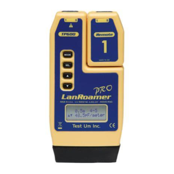
TP600
Part No.
™
LanRoverPRO
Test Set
Operating Instructions
Warning!
Do not attach to energized cables. The LanRoverPRO
be damaged.
Caution!
Improperly crimped, damaged or un-crimped plugs can
™
damage the jacks on the LanRoverPRO
proper termination and crimping before inserting into the
tester. Contacts should always be recessed into the plastic
grooves of the plug. Do not use with 6 position plugs (RJ11)
without an adapter.
FEATURES
• Auto-on and auto-off when testing cables, just plug both ends
into tester!
• Two-line by 16-character full alphanumeric LCD with icons for
clear results
• Cable test results displayed in wire map format with a message
line for shorts and split pairs
• Tests for shorts, opens, miswires, reversals and split pairs
with remote connected
• Pre-test – One-ended testing for shorts, opens and split
pairs (no remote)
--1--
• Displays PASS icon and sounds beeper (optional) for
T568A/B passing cables
• Length measurement in feet or meters using cable
capacitance method
• Tone generator mode for use with tone tracers
• Auto-off in any mode and low power consumption for
long battery life
• Snap-together case for easy storage of a remote and
convenient patch cable testing
DESCRIPTION
The LanRoverPRO
™
buttons. One remote attaches to the main unit for storage or
may
patch cable testing. The rubber end cap at the bottom is the
battery compartment cover.
The LanRoverPRO
testing with a remote. This yields maximum battery life and
takes advantage of the fact that the auto-on feature effectively
synchronizes the test cycle to the cable being connected for
. Inspect plugs for
results in 2 seconds. The tester powers on and testing begins
automatically when a connection from the main unit to the
remote is sensed. The tester will automatically power off within
5 seconds of the cable being disconnected.
Upon completion of the test, the wire map display, ID and any
faults are displayed. The top line of numbers on the display
represents the connector pins on the main unit. The second
line of pin numbers is the connector pin numbers of the remote,
normally being the same as the top line for a normal data
cable. If there is a miswire, the numbers on the second line
will indicate the pin numbers detected. If no connection was
detected for some of the pins, the second line will be blank
in those pin locations. If a short is detected, the second line
will have a flashing "x" in that position and the specific short
condition displayed on the third line. If a split pair is detected,
those pin positions on the second line will be flashing the
pin numbers detected from the remote and the specific split
condition displayed on the third line. If there are multiple errors
™
has an LCD display and four momentary
™
starts in an off condition when cable
--2--
to display on the third line, the messages are displayed in
sequence until all are displayed. The ID icon will have a number
directly below it indicating the remote ID number.
™
The LanRoverPRO
is powered on by pressing any of the four
buttons. The tester will turn on in the last mode used before
turning off. There are four modes of operation as described below.
In any mode, pressing the MODE button causes the mode select
screen to be displayed. The TURN OFF message is usually the
first one displayed. Subsequent presses of the MODE button
cycle through the other modes. Pressing the SEL button causes
the currently displayed mode to be entered.
Test/Pre-test – If a remote is sensed, the tester reverts to
the power off cable test described above (Test). If there is no
™
remote, the LanRoverPRO
uses the length and cable test
capability to attempt to measure a cable for shorts, opens and
split pairs (Pre-test). TEST and the current pair under test icons
being on indicate a test in progress. The results are displayed
as messages on the LCD. Because a test can take up to about
5 seconds to complete, the SEL button, which immediately
starts a new test, should be pressed whenever a new cable
is connected for pre-test. Partial and erroneous results will be
displayed until a complete test cycle has been run on a cable.
Length – The length mode measures the length of a cable by
measuring its capacitance and using the capacitance per unit
length (length constant) to calculate the length. The length is
displayed on the LCD along with the current value of the length
constant. The SEL button changes the pair being measured in
a 1-2, 3-6, 4-5, 7-8 and auto-select sequence. The pair number
is displayed next to the length except in auto-select mode. If
a selected pair has a fault, the fault replaces the length reading
on the LCD. In auto-select mode, the tester automatically selects
a pair without a fault. The length constant is changed with the
up and down arrows. The CAL icon is on while adjusting the
constant. If network terminator patterns are found in length
mode, the tester will display "T Ring Network??", "xbase-T
Network?" or "Network?" (all four lines terminated).
Tone – The tone mode generates audio tones for use with
tone tracers on all pairs, a selected pair or a selected pin. The
signal generated on a pair has the signal on one pin and the
--3--
Advertisement
Table of Contents

Related Manuals for Test-Um lanroverpro TP600


Summary of Contents for Test-Um lanroverpro TP600
-
Page 1: Operating Instructions
• Displays PASS icon and sounds beeper (optional) for to display on the third line, the messages are displayed in T568A/B passing cables sequence until all are displayed. The ID icon will have a number directly below it indicating the remote ID number. •... - Page 2 complement of the signal on the other pin of the pair, yielding Cable Testing 4) The tester will power on immediately and indicate a test a nominal 10 volts peak-to-peak across the pair. The SEL button in progress by displaying the TEST icon. It will be followed To Test a Patch Cable (see “Caution!”...
- Page 3 To Measure Length Examples of Wiring Errors (Shielded) Miswire – A wire or both wires of a pair are not connected to the DARK LIGHT FLASHING correct pins at the other end of the cable. In TEST mode, the wire 1) Connect cable to main unit.
- Page 4 All units returned for warranty repair will be repaired or replaced free of charge, at the discretion of Test-Um Inc, and will be shipped freight prepaid. In the event that a sales receipt or other dated proof-of-purchase documentation is not available, a period of not more than 12 months from date of manufacture shall apply.
Need help?
Do you have a question about the lanroverpro TP600 and is the answer not in the manual?
Questions and answers