Table of Contents
Advertisement
Advertisement
Chapters
Table of Contents
Troubleshooting

Related Manuals for Yamaha 2001 V Star XVS650A


Summary of Contents for Yamaha 2001 V Star XVS650A
- Page 1 OWNER’S MANUAL XVS650 XVS650A 5BN-28199-21...
- Page 3 EAU00000 Congratulations on your purchase of the Yamaha XVS650/XVS650A. This model is the result of Yamaha’s vast experience in the production of fine sporting, touring, and pacesetting racing machines. It represents the high degree of craftsmanship and reliability that have made Yamaha a leader in these fields.
- Page 4 This manual should be considered a permanent part of this motorcycle and should remain with it even if the motorcycle is subsequently sold. Yamaha continually seeks advancements in product design and quality. Therefore, while this manual contains the most current product information available at the time of printing, there may be minor discrepancies between your motorcycle and this manual.
-
Page 5: Important Manual Information
IMPORTANT MANUAL INFORMATION EW000002 WARNING PLEASE READ THIS MANUAL CAREFULLY AND COMPLETELY BEFORE OPERATING THIS MOTORCYCLE. - Page 6 IMPORTANT MANUAL INFORMATION EAU03337 XVS650/XVS650A OWNER’S MANUAL © 2000 by Yamaha Motor Co., Ltd. 1st Edition, September 2000 All rights reserved. Any reprinting or unauthorized use without the written permission of Yamaha Motor Co., Ltd. is expressly prohibited. Printed in Japan.
-
Page 7: Table Of Contents
EAU00009 TABLE OF CONTENTS 1 SAFETY INFORMATION 2 DESCRIPTION 3 INSTRUMENT AND CONTROL FUNCTIONS 4 PRE-OPERATION CHECKS 5 OPERATION AND IMPORTANT RIDING POINTS 6 PERIODIC MAINTENANCE AND MINOR REPAIR 7 MOTORCYCLE CARE AND STORAGE 8 SPECIFICATIONS 9 CONSUMER INFORMATION INDEX... -
Page 9: Safety Information
SAFETY INFORMATION Safe riding ..................1-1 Protective apparel ................1-3 Modifications ..................1-3 Loading and accessories ..............1-3 Gasoline and exhaust gas..............1-5 Location of important labels .............. 1-7... -
Page 10: Safe Riding
S AFETY INFORMATION EAU03633 MOTORCYCLES ARE SINGLE TRACK VEHICLES. THEIR SAFE USE AND OPERATION ARE DEPENDENT UPON THE USE OF PROPER RIDING TECHNIQUES AS WELL AS THE EXPERTISE OF THE OPERATOR. EVERY OPERATOR SHOULD KNOW THE FOLLOWING REQUIREMENTS BEFORE RIDING THIS MOTORCYCLE. HE OR SHE SHOULD: 1. -
Page 11: Safety Information
SAFETY INFORMATION 4. Many motorcycle accidents involve inexperienced operators. In fact, many operators who have been involved in accidents do not even have a current motorcycle license. a. Make sure that you are qualified and that you only lend your motorcycle to other qualified operators. -
Page 12: Protective Apparel
6. Passengers should also observe the precautions mentioned above. Modifications Modifications made to this motorcycle not approved by Yamaha, or the removal of original equipment, may render the motorcycle unsafe for use and may cause severe personal injury. Modifications may also make your motorcycle illegal to use. - Page 13 Genuine Yamaha accessories have been specifically designed for use on this motorcycle. Since Yamaha cannot test all other accessories that may be available, you must personally be responsible for the proper selection, installation and use of non-Yamaha accessories. Use extreme caution when selecting and installing any accessories.
-
Page 14: Gasoline And Exhaust Gas
SAFETY INFORMATION b. Bulky or large accessories may seriously affect the stability of the motorcycle due to aerodynamic effects. Wind may attempt to lift the motorcycle, or the motorcycle may become unstable in cross winds. These accessories may also cause instability when passing or being passed by large vehicles. - Page 15 SAFETY INFORMATION 4. When transporting the motorcycle in another vehicle, make sure that it is kept upright and that the fuel cock is turned to “ON” or “RES” (for vacuum type) / “OFF” (for manual type). If it should lean over, gasoline may leak out of the carburetor or fuel tank.
-
Page 16: Location Of Important Labels
SAFETY INFORMATION EAU02977 Location of important labels Please read the following important labels carefully before operating this motorcycle. -
Page 17: Description
DESCRIPTION Left view (XVS650) ................2-1 Right view (XVS650) ................2-2 Left view (XVS650A) ................2-3 Right view (XVS650A)................ 2-4 Controls and instruments (XVS650/XVS650A) ........2-5... -
Page 18: Left View (Xvs650)
D ESCRIPTION EAU00026 Left view (XVS650) 1. Shift pedal (page 3-4) 5. Helmet holder (page 3-12) 2. Fuel cock (page 3-7) 6. Storage compartment (page 3-13) 3. Starter (choke) knob (page 3-9) 7. Owner’s tool kit (page 6-1) 4. Shock absorber spring preload adjusting ring (page 3-14) -
Page 19: Right View (Xvs650)
DESCRIPTION Right view (XVS650) 8. Engine oil filter element (page 6-9) 11. Main switch/steering lock (page 3-1) 9. Battery (page 6-29) 12. Air filter element (page 6-13) 10. Fuses (page 6-31) 13. Brake pedal (page 3-5) -
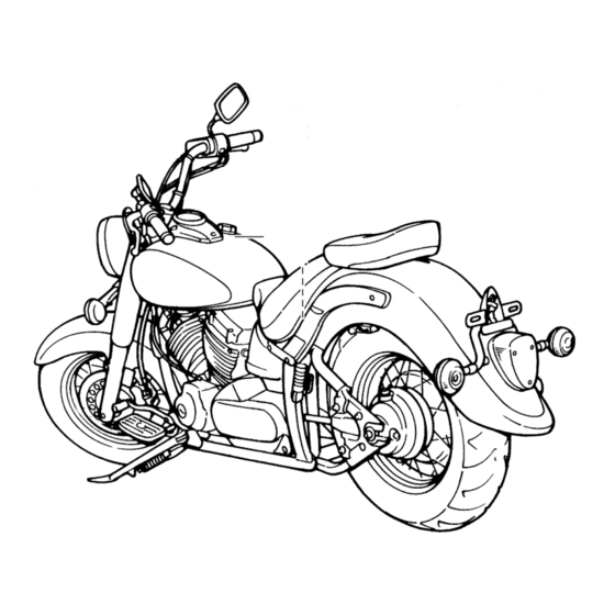
Page 20: Left View (Xvs650A)
DESCRIPTION Left view (XVS650A) 1. Shift pedal (page 3-5) 5. Helmet holder (page 3-12) 2. Fuel cock (page 3-7) 6. Storage compartment (page 3-13) 3. Starter (choke) knob (page 3-9) 7. Owner’s tool kit (page 6-1) 4. Shock absorber spring preload adjusting ring (page 3-14) -
Page 21: Right View (Xvs650A)
DESCRIPTION Right view (XVS650A) 8. Engine oil filter element (page 6-9) 11. Main switch/steering lock (page 3-1) 9. Battery (page 6-29) 12. Air filter element (page 6-13) 10. Fuses (page 6-31) 13. Brake pedal (page 3-5) -
Page 22: Controls And Instruments (Xvs650/Xvs650A)
DESCRIPTION Controls and instruments (XVS650/XVS650A) 1. Clutch lever (page 3-4) 2. Left handlebar switches (page 3-3) 3. Speedometer unit (page 3-2) 4. Fuel tank cap (page 3-6) 5. Right handlebar switches (page 3-3) 6. Throttle grip (page 6-15) 7. Brake lever (page 3-5) -
Page 23: Instrument And Control Functions
INSTRUMENT AND CONTROL FUNCTIONS Main switch/steering lock ..............3-1 Indicator and warning lights ............. 3-2 Speedometer unit ................3-2 Handlebar switches ................3-3 Clutch lever ..................3-4 Shift pedal (XVS650)................3-4 Shift pedal (XVS650A) ............... 3-5 Brake lever ..................3-5 Brake pedal .................. -
Page 24: Main Switch/Steering Lock
I NSTRUMENT AND CONTROL FUNCTIONS EAU00027 1. Push. 2. Turn. EAU00029 EAU00040 Main switch/steering lock LOCK EW000016 The steering is locked, and all electrical WARNING The main switch/steering lock controls systems are off. The key can be re- the ignition and lighting systems, and is Never turn the key to “OFF”... -
Page 25: Indicator And Warning Lights
1. Tripmeter reset knob the engine is defective. When this oc- 2. Turn signal indicator light “ ” 2. Speedometer curs, have the Yamaha dealer check 3. Neutral indicator light “ ” 3. Odometer 4. Engine trouble warning light “... -
Page 26: Handlebar Switches
INSTRUMENT AND CONTROL FUNCTIONS EAU00119 Pass switch “ ” Press this switch to flash the headlight. EAU00121 Dimmer switch Set this switch to “ ” for the high beam and to “ ” for the low beam. EAU00129 1. Turn signal switch Horn switch “... -
Page 27: Clutch Lever
INSTRUMENT AND CONTROL FUNCTIONS EAU00138 XVS650 Engine stop switch Set this switch to “ ” to stop the en- gine in case of an emergency, such as when the motorcycle overturns or when the throttle cable is stuck. 1. Clutch lever 1. -
Page 28: Shift Pedal (Xvs650A)
INSTRUMENT AND CONTROL FUNCTIONS XVS650A XVS650 1. Shift pedal 1. Brake lever 1. Brake pedal EAU01215 EAU00158 EAU00162 Shift pedal (XVS650A) Brake lever Brake pedal The shift pedal is located on the left The brake lever is located at the right The brake pedal is on the right side of side of the engine and is used in com- handlebar grip. -
Page 29: Fuel Tank Cap
INSTRUMENT AND CONTROL FUNCTIONS 2. Turn the key counterclockwise to XVS650A the original position, and then re- move it. NOTE: The fuel tank cap cannot be installed unless the key is in the lock. In addition, the key cannot be removed if the cap is not properly installed and locked. -
Page 30: Fuel
INSTRUMENT AND CONTROL FUNCTIONS EAU00185 Off position CAUTION: Immediately wipe off spilled fuel with a clean, dry, soft cloth, since fuel may deteriorate painted surfac- es or plastic parts. EAU00192 1. Fuel tank filler tube 1. Arrow mark positioned over “OFF” Recommended fuel: 2. - Page 31 INSTRUMENT AND CONTROL FUNCTIONS Normal position Reserve position 1. Arrow mark positioned over “ON” 1. Arrow mark positioned over “RES” With the fuel cock lever in this position, This indicates reserve. With the fuel fuel flows to the carburetors. Turn the cock lever in this position, the fuel re- fuel cock lever to this position when serve is made available.
-
Page 32: Starter (Choke) Knob
INSTRUMENT AND CONTROL FUNCTIONS ECA00038 XVS650 CAUTION: Do not use the starter (choke) for more than 3 minutes as the exhaust pipe may discolor from excessive heat. In addition, extended use of the starter (choke) will cause after- burning. If this occurs, turn off the starter (choke). - Page 33 INSTRUMENT AND CONTROL FUNCTIONS XVS650 XVS650 1. Bolt (× 2) 1. Seat holder 2. Seat holder 2. Projection 3. Projection Rider seat To install the passenger seat To remove the rider seat Insert the projection on the front of the 1.
-
Page 34: Seats (Xvs650A)
INSTRUMENT AND CONTROL FUNCTIONS XVS650A XVS650A XVS650A 1. Bolt 1. Seat holder (× 2) 1. Bolt 2. Projection (× 2) Rider seat EAU01888 Seats (XVS650A) To install the passenger seat To remove the rider seat Insert the projections on the front of the 1. -
Page 35: Helmet Holder
INSTRUMENT AND CONTROL FUNCTIONS XVS650A 1. Seat holder 1. Helmet holder 2. Projection 2. Unlock. To install the rider seat EAU00260 Helmet holder 1. Insert the projection on the front of To open the helmet holder, insert the the rider seat into the holder as key into the lock, and then turn the key shown, place the seat in the origi- as shown. -
Page 36: Storage Compartment
INSTRUMENT AND CONTROL FUNCTIONS 1. Storage compartment cover 1. Storage compartment 2. Storage compartment lock cover 2. Storage compartment cover To open the storage compartment 3. Storage compartment lock To close the storage compartment 1. Slide the lock cover open, insert EAU01869 1. -
Page 37: Adjusting The Shock Absorber Assembly
Never attempt to turn an adjusting CI-01E Minimum Stan- Maximum (hard) formance. mechanism beyond the maximum (soft) dard Always have a Yamaha dealer or minimum settings. Setting service the shock absorber. 3. Install the passenger and rider seats. 3-14... -
Page 38: Luggage Strap Holders
There is a luggage strap holder on responsibility of raising the side- each passenger footrest. stand before starting off. Therefore, check this system regularly as de- scribed below and have a Yamaha dealer repair it if it does not function properly. 3-15... -
Page 39: Ignition Circuit Cut-Off System
Periodically check the operation of the ignition circuit cut-off system according to the following procedure. EW000045 WARNING If a malfunction is noted, have a Yamaha dealer check the system before riding. 3-16... - Page 40 5. Push the start switch. Does the engine start? The neutral switch may be defective. The motorcycle should not be ridden until checked by a Yamaha dealer. With the engine still running: 6. Move the sidestand up. 7. Keep the clutch lever pulled.
-
Page 41: Pre-Operation Checks
PRE-OPERATION CHECKS Pre-operation check list ..............4-1... - Page 42 • Check vehicle for oil leakage. Final gear oil • Check vehicle for oil leakage. 6-11–6-12 • Check operation. • If soft or spongy, have Yamaha dealer bleed hydraulic system. • Check lever free play. Front brake • Adjust if necessary. 6-20, 6-23–6-25 •...
- Page 43 • Check operation of ignition circuit cut-off system. Sidestand switch 3-15 • If system is defective, have Yamaha dealer check vehicle. NOTE: Pre-operation checks should be made each time the motorcycle is used. Such an inspection can be accomplished in a very short time;...
-
Page 45: Operation And Important Riding Points
OPERATION AND IMPORTANT RIDING POINTS Starting and warming up a cold engine ..........5-1 Starting a warm engine ..............5-2 Shifting ....................5-3 Tips for reducing fuel consumption ........... 5-4 Engine break-in ................. 5-4 Parking ....................5-5... -
Page 46: Starting And Warming Up A Cold Engine
If the should be on, otherwise have a sidestand is not raised com- Yamaha dealer check the electrical cir- pletely, it could contact the cuit. ground and distract the opera- 4. Turn the starter (choke) on and tor, resulting in a possible loss completely close the throttle. -
Page 47: Starting A Warm Engine
If the warning light does not go off after starting with suffi- 5. Start the engine by pushing the cient engine oil, have a Yamaha deal- start switch. er check the electrical circuit. 6. After starting the engine, move the... -
Page 48: Shifting
OPERATION AND IMPORTANT RIDING POINTS Always use the clutch while XVS650 XVS650A changing gears to avoid dam- aging the engine, transmission, and drive train, which are not designed withstand shock of forced shifting. 1. Shift pedal 1. Shift pedal N. Neutral position N. -
Page 49: Tips For Reducing Fuel Consumption
(e.g., in traffic jams, at traf- The vehicle can now be operated fic lights or at railroad crossings). normally. EC000049 CAUTION: If any engine trouble should occur during the engine break-in period, immediately have a Yamaha dealer check the vehicle. -
Page 50: Parking
OPERATION AND IMPORTANT RIDING POINTS EAU00457 Parking When parking, stop the engine, re- move the key from the main switch, and then turn the fuel cock lever to “OFF”. EW000058 WARNING Since the engine and exhaust system can become very hot, park in a place where pedestri- ans or children are not likely to touch them. -
Page 51: Periodic Maintenance And Minor Repair
PERIODIC MAINTENANCE AND MINOR REPAIR Owner’s tool kit ............6-1 Checking and lubricating the cables ....6-25 Periodic maintenance and lubrication chart ..6-2 Checking and lubricating the throttle grip and cable ............... 6-25 Removing and installing panels ......6-5 Checking and lubricating the brake and Checking the spark plugs ........6-7 shift pedals ............ -
Page 52: Owner's Tool Kit
If you do not have the tools or experi- VALS MAY NEED TO BE SHORT- ence required for a particular job, have ENED. a Yamaha dealer perform it for you. EW000060 WARNING If you are not familiar with motor- cycle maintenance work, have a... -
Page 53: Periodic Maintenance And Lubrication Chart
The annual checks must be performed every year, except if a kilometer-based maintenance is performed instead. From 50,000 km, repeat the maintenance intervals starting from 10,000 km. Items marked with an asterisk should be performed by a Yamaha dealer as they require special tools, data and techni- cal skills. - Page 54 PERIODIC MAINTENANCE AND MINOR REPAIR ODOMETER READING (×1,000 km) ANNUAL ITEM CHECK OR MAINTENANCE JOB CHECK • Check tread depth and for damage. • Replace if necessary. √ √ √ √ Tires • Check air pressure. • Correct if necessary. √...
- Page 55 PERIODIC MAINTENANCE AND MINOR REPAIR EAU03541 NOTE: The air filter needs more frequent service if you are riding in unusually wet or dusty areas. Hydraulic brake service • Regularly check and, if necessary, correct the brake fluid level. • Every two years replace the internal components of the brake master cylinder and caliper, and change the brake fluid. •...
-
Page 56: Removing And Installing Panels
PERIODIC MAINTENANCE AND MINOR REPAIR XVS650 XVS650A 1. Panel A 1. Panel A 1. Panel B EAU01122 Removing and installing panels The panels shown above need to be removed to perform some of the main- tenance jobs described in this chapter. Refer to this section each time a panel needs to be removed and installed. - Page 57 PERIODIC MAINTENANCE AND MINOR REPAIR XVS650 XVS650A 1. Bolt (× 4) 1. Bolt (× 4) 1. Bolt EAU01573 EAU00491 Panel A Panel B To remove the panel To remove the panel Remove the bolts, and then take the Remove the bolt, and then pull the pan- panel off.
-
Page 58: Checking The Spark Plugs
PERIODIC MAINTENANCE AND MINOR REPAIR 1. Spark plug cap 1. Spark plug wrench To install the panel To remove a spark plug EAU03329 Checking the spark plugs Place the panel in the original position, 1. Remove the spark plug cap. The spark plugs are important engine and then install the bolt. -
Page 59: To Install Spark Plug
Do not attempt to diagnose such problems yourself. Instead, have a NOTE: Yamaha dealer check the motorcycle. If a torque wrench is not available when 3. Check each spark plug for elec- installing a spark plug, a good estimate trode erosion and excessive car- of the correct torque is 1/4–1/2 turn... -
Page 60: Engine Oil And Oil Filter Element
PERIODIC MAINTENANCE AND MINOR REPAIR EAU03835 Left side Engine oil and oil filter element The engine oil level should be checked before each ride. In addition, the oil must be changed and the oil filter ele- ment replaced at the intervals specified in the periodic maintenance and lubri- cation chart. - Page 61 PERIODIC MAINTENANCE AND MINOR REPAIR Right side 1. Outer oil filter element cover 1. Inner oil filter element cover 1. Oil filter element 2. Bolt (× 3) 2. Bolt (× 5) 2. O-ring 5. Remove the oil filter element and NOTE: O-ring.
-
Page 62: Final Gear Oil
If any page (since the engine oil also leakage is found, have a Yamaha deal- lubricates the clutch), do not Recommended engine oil: er check and repair the motorcycle. In mix any chemical additives with See page 8-1. - Page 63 PERIODIC MAINTENANCE AND MINOR REPAIR NOTE: Recommended final gear oil: The oil level should be at the brim of See page 8-2. the filler hole. Oil quantity: 3. If the oil is below the brim of the fill- 0.19 L er hole, add sufficient oil of the rec- ommended type to raise it to the NOTE:...
-
Page 64: Cleaning The Air Filter Element
PERIODIC MAINTENANCE AND MINOR REPAIR 1. Air filter case cover 1. Air filter element 1. Air filter element holder 2. Screw (× 3) 2. Projection 3. Lightly tap the air filter element to 3. Slot EAU00586* remove most of the dust and dirt, Cleaning the air filter element 4. -
Page 65: Adjusting The Carburetors
The carburetors are important parts of the engine and require very sophisti- cated adjustment. Therefore, most car- buretor adjustments should be left to a Yamaha dealer, who has the neces- sary professional knowledge and expe- rience. The adjustment described in 1. Match marks... -
Page 66: Adjusting The Engine Idling Speed
4,000–5,000 r/min. NOTE: Engine idling speed: The engine is warm when it quickly re- 1,150–1,250 r/min sponds to the throttle. NOTE: If the specified idling speed cannot be obtained as described above, have a Yamaha dealer make the adjustment. 6-15... -
Page 67: Adjusting The Valve Clearance
(2.00 kg/cm (2.25 kg/cm from occurring, the valve clearance regarding the specified tires. 2.00 bar) 2.25 bar) must be adjusted by a Yamaha dealer 200 kPa 250 kPa at the intervals specified in the periodic Tire air pressure 90 kg–maximum (2.00 kg/cm... - Page 68 Tire information in it, or if the sidewall is cracked, con- ger, and accessories (cowling, sad- This motorcycle is equipped with tube tact a Yamaha dealer immediately and dlebags, etc. if approved for this have the tire replaced. tires. model) does not exceed the maxi- CE-20E mum load of the motorcycle.
-
Page 69: Spoke Wheels
If any dam- ing the tires, should be left to a Yamaha Motor Co., Ltd. age is found, have a Yamaha Yamaha dealer, who has the dealer replace the wheel. Do not necessary professional knowl-... -
Page 70: Adjusting The Clutch Lever Free Play
PERIODIC MAINTENANCE AND MINOR REPAIR 7. Tighten the locknut at the clutch lever and the crankcase. 1. Locknut 1. Clutch lever free play adjusting nut 2. Clutch lever free play adjusting bolt 2. Locknut c. Clutch lever free play 3. If the specified clutch lever free EAU00694 play could be obtained as de- Adjusting the clutch lever free... -
Page 71: Adjusting The Brake Lever Free Play
Brake lever free play system. If there is air in the hy- 2. Brake lever free play adjusting bolt 1. Loosen the locknut at the brake draulic system, have a Yamaha EAU00696 lever. dealer bleed the system before Adjusting the brake lever free 2. -
Page 72: Adjusting The Brake Pedal Position And Free Play
Periodically WARNING lower the brake pedal, turn the ad- check the brake pedal position and, if It is advisable to have a Yamaha justing bolt in direction b. necessary, adjust it as follows. dealer make these adjustments. -
Page 73: Adjusting The Rear Brake Light Switch
PERIODIC MAINTENANCE AND MINOR REPAIR 1. Brake pedal free play adjusting nut 1. Rear brake light switch 2. Rear brake light switch adjusting nut Brake pedal free play EAU00713 The brake pedal free play should mea- Adjusting the rear brake light sure 20–30 mm at the brake pedal end. -
Page 74: Checking The Front Brake Pads And Rear Brake Shoes
If a brake shoe has worn to the indicators have almost disappeared, point that the wear indicator reaches have a Yamaha dealer replace the the wear limit line, have a Yamaha brake pads as a set. dealer replace the brake shoes as a set. -
Page 75: Checking The Brake Fluid Level
However, if the fluid reservoir is level. brake fluid level goes down sud- Use only the recommended quali- denly, have a Yamaha dealer ty brake fluid, otherwise the rubber check the cause. seals may deteriorate, causing leakage and poor braking perfor- mance. -
Page 76: Changing The Brake Fluid
EAU02962 EAU03764 Changing the brake fluid Checking and lubricating the Checking and lubricating the Have a Yamaha dealer change the cables throttle grip and cable brake fluid at the intervals specified in The operation of all control cables and The operation of the throttle grip and... -
Page 77: Checking And Lubricating The Brake And Shift Pedals
PERIODIC MAINTENANCE AND MINOR REPAIR Recommended lubricant: Throttle cable: Engine oil Throttle grip housing and grip: Lithium-soap-based grease (all-purpose grease) EAU03370 EAU03164 Checking and lubricating the Checking and lubricating the brake and shift pedals brake and clutch levers The operation of the brake and shift The operation of the brake and clutch pedals should be checked before each levers should be checked before each... -
Page 78: Checking And Lubricating The Sidestand
EW000113 WARNING If the sidestand does not move up and down smoothly, have a Yamaha dealer check or repair it. 6-27... -
Page 79: Checking The Steering
2. Hold the lower ends of the front fork legs and try to move them for- ward and backward. If any free play can be felt, have a Yamaha dealer check or repair the steer- ing. To check the operation... -
Page 80: Checking The Wheel Bearings
Batteries produce explosive hy- smoothly, have a Yamaha dealer EC000101 drogen gas. Therefore, keep CAUTION: check the wheel bearings. - Page 81 PERIODIC MAINTENANCE AND MINOR REPAIR To charge the battery EC000102 CAUTION: Have a Yamaha dealer charge the bat- Always keep battery tery as soon as possible if it seems to charged. Storing a discharged have discharged. Keep in mind that the...
-
Page 82: Replacing The Fuses
3. Spare main fuse 3. Headlight fuse 4. If the fuse immediately blows 4. Carburetor heater fuse EAU00825 again, have a Yamaha dealer 5. Spare fuse Replacing the fuses check the electrical system. The fuses are located behind panel B. -
Page 83: Replacing The Headlight Bulb
PERIODIC MAINTENANCE AND MINOR REPAIR 1. Screw (× 2) 1. Headlight coupler 1. Headlight bulb holder 2. Headlight bulb cover 3. Unhook the headlight bulb holder, EAU00834 Replacing the headlight bulb 2. Disconnect the headlight coupler, and then remove the defective This motorcycle is equipped with a and then remove the headlight bulb. -
Page 84: Replacing A Turn Signal Light Bulb Or The Tail/Brake Light Bulb
1. Remove the lens by removing the screws. ing the screws. screws. EC000108 7. Have a Yamaha dealer adjust the CAUTION: 2. Remove the defective bulb by headlight beam if necessary. pushing it in and turning it counter- Do not overtighten the screws, oth- erwise the lens may break. -
Page 85: Supporting The Motorcycle
PERIODIC MAINTENANCE AND MINOR REPAIR EAU01579 To service the rear wheel XVS650A Supporting the motorcycle Raise the rear wheel off the ground by Since this model is not equipped with a using a motorcycle stand or, if a motor- centerstand, follow these precautions cycle stand is not available, by placing when removing the front and rear a jack either under each side of the... -
Page 86: Front Wheel
WARNING page 6-34. 2. Lift the wheel up between the fork It is advisable to have a Yamaha 4. Pull the wheel axle out, and then legs. dealer service the wheel. remove the wheel. -
Page 87: Rear Wheel
EW000122 fork operation. WARNING 6. Tighten the wheel axle to the It is advisable to have a Yamaha specified torque. dealer service the wheel. Securely support the motorcycle Tightening torque: so that there is no danger of it 1. - Page 88 PERIODIC MAINTENANCE AND MINOR REPAIR 3. Install the brake rod onto the brake camshaft lever, and then install the brake pedal free play adjusting nut onto the brake rod. 4. Install the brake torque rod bolts, and then tighten them to the spec- ified torque.
-
Page 89: Troubleshooting
However, should your motorcycle require any repair, take it to a Yamaha dealer, whose skilled technicians have the necessary tools, experience, and know-how to service the motorcycle properly. -
Page 90: Troubleshooting Chart
Remove the spark plugs and check the electrodes. The engine does not start. Have a Yamaha dealer check the vehicle. Check the battery. 4. Battery The engine turns over The battery is good. -
Page 91: Motorcycle Care And Storage
MOTORCYCLE CARE AND STORAGE Care ....................7-1 Storage ....................7-4... - Page 92 M OTORCYCLE CARE AND STORAGE EAU03412 Care Before cleaning Cleaning 1. Cover the muffler outlets with plas- ECA00010 While the open design of a motorcycle CAUTION: tic bags after the engine has reveals the attractiveness of the tech- Avoid using strong acidic wheel cooled down.
- Page 93 MOTORCYCLE CARE AND STORAGE Do not use any harsh chemical For motorcycles equipped with After riding in the rain, near the sea or products on plastic parts. Be a windshield: Do not use strong on salt-sprayed roads sure to avoid using cloths or cleaners or hard sponges as Since sea salt or salt sprayed on roads sponges which have been in...
- Page 94 EWA00031 rosion. WARNING NOTE: Consult a Yamaha dealer for advice on Make sure that there is no oil or After cleaning what products to use. wax on the brakes or tires. 1. Dry the motorcycle with a chamois If necessary, clean the brake or an absorbing cloth.
- Page 95 MOTORCYCLE CARE AND STORAGE Storage Long-term c. Install the spark plug caps onto the Before storing your motorcycle for sev- spark plugs, and then place the eral months: spark plugs on the cylinder head Short-term 1. Follow all the instructions in the so that the electrodes are ground- Always store your motorcycle in a cool, “Care”...
- Page 96 MOTORCYCLE CARE AND STORAGE 7. Check and, if necessary, correct the tire air pressure, and then lift the motorcycle so that both of its wheels are off the ground. Alterna- tively, turn the wheels a little every month in order to prevent the tires from becoming degraded in one spot.
-
Page 97: Specifications
SPECIFICATIONS Specifications ..................8-1 Conversion table ................8-6... - Page 98 S PECIFICATIONS EAU01038 Specifications CS-01E Model XVS650/XVS650A Engine Dimensions Engine type Air-cooled 4-stroke, SOHC XVS650 Cylinder arrangement V-type 2-cylinder Overall length 2,340 mm Displacement 649 cm Bore × stroke 81 × 63 mm Overall width 880 mm Overall height 1,070 mm Compression ratio Seat height 695 mm...
- Page 99 SPECIFICATIONS Spark plug CAUTION: Manufacturer/model NGK / DPR7EA-9 or Be sure to use motor oils that do not contain anti-friction DENSO / X22EPR-U9 modifiers. Passenger motor oils (often labeled 0.8– 0.9 mm “ENERGY CONSERVING II”) contain anti-friction additives which will cause clutch and/or starter clutch slippage, result- Clutch type Wet, multiple-disc ing in reduced component life and poor engine performance.
- Page 100 SPECIFICATIONS XVS650A 90 kg–maximum* Frame type Double cradle Front 200 kPa (2.00 kg/cm , 2.00 bar) Caster angle 35° Rear 250 kPa (2.50 kg/cm , 2.50 bar) Trail 145 mm * Total weight of rider, passenger, cargo and accessories Tires XVS650A XVS650 Front...
- Page 101 SPECIFICATIONS Wheels Suspension XVS650 Front Telescopic fork Front Rear Swingarm (monocross) Type Spoke wheel Spring/shock absorber 19 × MT 2.50 Size Front Coil spring / oil damper Rear Rear Coil spring / gas-oil damper Type Spoke wheel Wheel travel 15 M/C × MT 3.50 Size XVS650 XVS650A...
- Page 102 SPECIFICATIONS Bulb voltage, wattage × quantity 12 V, 60/55 W × 1 Headlight 12 V, 5/21 W × 1 Tail/brake light 12 V, 21 W × 4 Turn signal light 12 V, 1.7 W × 1 Meter lighting 12 V, 1.7 W × 1 Neutral indicator light 12 V, 1.7 W ×...
-
Page 103: Conversion Table
SPECIFICATIONS EAU01064 Conversion table CS-02E Conversion table All specification data in this manual are listed in SI and METRIC TO IMPERIAL METRIC UNITS. Metric unit Multiplier Imperial unit Use this table to convert METRIC unit data to IMPERIAL m·kg 7.233 ft·lb m·kg 86.794... -
Page 105: Consumer Information
CONSUMER INFORMATION Identification numbers ............... 9-1 Key identification number ..............9-1 Vehicle identification number ............. 9-1 Model label ..................9-2 Motorcycle noise regulation (for Australia) ........9-2... - Page 106 Record the key identification number, vehicle identification number and mod- el label information in the spaces pro- vided below for assistance when ordering spare parts from a Yamaha dealer or for reference in case the vehi- cle is stolen. 1. Key identification number 1.
- Page 107 (b) The use of the vehicle after such label in the space provided. This infor- device or element of design has mation will be needed when ordering been removed or rendered inoper- spare parts from a Yamaha dealer. ative by any person.
- Page 108 I NDEX 1 0 - Air filter element, cleaning ......6-13 Final gear oil.......... 6-11 Neutral indicator light .......3-2 Front fork, checking ....... 6-27 Noise regulation (for Australia) ....9-2 Fuel ............3-7 Battery ...........6-29 Fuel cock..........3-7 Brake and clutch levers, checking Panels, removing and installing....6-5 Fuel consumption, tips for reducing ..
-
Page 109: Throttle Grip
INDEX Steering, checking ......... 6-28 Storage............ 7-4 Storage compartment ......3-13 Supporting the motorcycle ..... 6-34 Throttle cable free play, adjusting ..6-15 Throttle grip and cable, checking and lubricating........6-25 Tires ............6-16 Tool kit............. 6-1 Troubleshooting........6-38 Troubleshooting chart......6-39 Turn signal indicator light ...... - Page 112 YAMAHA MOTOR CO., LTD. PRINTED ON RECYCLED PAPER PRINTED IN JAPAN 2000 · 10 - 0.3 × 1 CR...
Need help?
Do you have a question about the 2001 V Star XVS650A and is the answer not in the manual?
Questions and answers