Table of Contents
Advertisement
Danger
Water heater for other than recreational vehicle installation only
READ ALL OF THE INSTRUCTIONS THOROUGHLY BEFORE OPERATING THIS WATER HEATER.
This manual provides information on the installation, operation, and maintenance of the water heater. For
proper operation and safety, it is important to follow the instructions and adhere to the safety precautions.
A licensed professional must install the water heater according to the exact instructions of the manual.
If the information in these instructions is not followed exactly, fire or explosion
Warning
may result causing property damage, personal injury, or death.
- Do not store or use gasoline or other flammable vapors and liquids in the vicinity of this or any other
appliance.
- What to do if you smell gas
• Do not try to light any appliance.
• Do not touch any electrical switch; do not use any phone in your building.
• Immediately call your gas supplier from a neighbor's phone. Follow the gas supplier's instructions.
• If you cannot reach your gas supplier, call the fire department.
- Installation and service must be performed by a licensed professional.
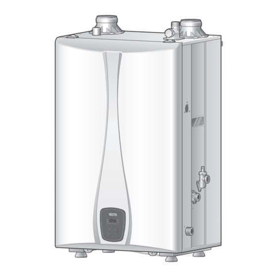
HYBRID WATER HEATER
Installation
Manual
Model
VH-150
VH-199
Keep this manual near the water heater for future reference
whenever maintance or service is required.
Advertisement
Table of Contents

Related Manuals for Vesta VH-150


Summary of Contents for Vesta VH-150
- Page 1 HYBRID WATER HEATER Installation Manual Model VH-150 VH-199 Keep this manual near the water heater for future reference whenever maintance or service is required. Danger Water heater for other than recreational vehicle installation only READ ALL OF THE INSTRUCTIONS THOROUGHLY BEFORE OPERATING THIS WATER HEATER.
-
Page 2: Safety Information
Safety Information The following safety symbols are used in this manual for user's safety. Read this manual carefully and follow all instructions to avoid property damage, fire, explosion, personal injury, or death. Danger Indicates an imminently hazardous situation which, if not avoided, will result in severe injury or death. Warning Indicates a potentially hazardous situation which, if not avoided, will result in injury or death. - Page 3 Warning • Do not store combustibles, such as papers or laundry, near the water heater or venting system. Failure to do so may result in fire or explosion. • Do not store or use gasoline or other flammable liquids near this water heater. Failure to do so may result in fire or explosion.
-
Page 4: Important Note For The State Of Massachusetts
Important Note for the State of Massachusetts From Massachusetts Rules and Regulations 248 CMR 5.08: (a) For all side wall horizontally vented gas fuelled equipment installed in every dwelling, building or structure used in whole or in part for residential purposes, including those owned or operated by the Commonwealth and where the side wall exhaust vent termination is less than seven (7) feet above finished grade in the area of the venting, including but not limited to decks and porches, the following requirements shall be satisfied. -
Page 5: Table Of Contents
Table of Contents Safety Information ........2 Installing a Vent ........22 Vent Type ................22 Important Note for the State of Vent Pipe Materials ............26 Massachusetts ........... 4 Vent Length ...............26 Connecting the Vent Clip ..........27 General Information ........6 Vent Termination .............27 Included Items .............. -
Page 6: General Information
General Information Included Items Optional Accessories The following items are included with the water heater. Check each The following optional accessories are not included with the water of the following items before installation. heater, but may be necessary for the installation. Check the need for any of the following optional accessories before installation. -
Page 7: Specifications
Specifications The following table shows the specifications for the water heater. Additional specifications about water, gas, electric, and air supplies (venting) appear in each installation section. Item VH-150 VH-199 Natural Gas 38,000–150,000 BTU/H 38,000–199,000 BTU/H Heat Capacity (Input) Propane Gas 38,000–150,000 BTU/H... -
Page 8: Rating Plate
If the water heater does not match each of these ratings, do not install the water heater. If the gas conversion is required, the included gas conversion kit must be used. Chauffe-eau Automatique Instantan Ventilation Directe VESTA. DS, INC. 2711 LBJ Freeway, Suite#320 Farmers Branch, Texas75234 1-800-761-0053... -
Page 9: Dimensions
Dimensions 12.30" (312.6 mm) Description Diameter Air intake 2" connector Flue connector 2" Hot water outlet 3/4" Cold water inlet 3/4" Pressure relief 3/4" valve connector Drain valve 3/4" Condensate 3/4" outlet 11.58" (294.2 mm) Gas inlet 3/4" 18.11" (460 mm) 2.20"... -
Page 10: Components
Components Air intake connector Flue connector Mixing valve Surge pressure Over heat preventer regulation valve Cold water block Tank heat exchanger assembly Air intake hose Flow control valve Low water cut off switch PCB assembly Condensate trap Air pressure switch Power Cable Rubber feet Installation Manual... - Page 11 Hot water outlet Cold water inlet Surge pressure regulation valve Pressure relief valve connector Duct assembly Drain valve Turbo fan assembly Front panel Gas pipe Gas valve General Information...
-
Page 12: Installing The Water Heater
Installing the Water Heater Installer Qualifications Water quality Water quality can have an impact on appliance longevity and may A licensed professional must install and inspect the appliance. A void the manufacturer's warranty. licensed professional is a person who is licensed for the following: To maintain the water heater properly, ensure that your water meets •... - Page 13 Clean, debris and chemical-free combustion • Install the exhaust vent in an area that is free from obstructions and does not allow the exhaust to accumulate. • Do not enclose the vent termination. • Do not install the water heater in areas where dust and debris •...
- Page 14 Mounting on the floor Mounting to the wall To mount the water heater on the floor: To mount the water heater to the wall: Check that the floor is even and rigid enough to support the Check that the wall is level and can support the weight of the water heater.
-
Page 15: Connecting The Gas Supply
Connecting the Gas Supply Gas Pipe Sizing Tables Gas pipe sizing is based on the gas type, supplied gas pressure, pressure drop in the system, and gas line type. The tables below are for reference only (when the gas supply is piping straight to the water heater with no connections to any other gas appliances). For gas pipe sizing, refer to the latest National Fuel Gas code, NFPA 54 and consult the gas pipe manufacturer for actual gas pipe capacities. -
Page 16: Gas Piping
• Leak test the appliance and its gas connection before Check for gas leaks at all joints. operating the water heater. • Do not attempt a field conversion without a Vesta conversion kit. Use the Vesta conversion kit to convert from Notice natural gas to propane or vice versa. -
Page 17: Inlet Gas Pressure
• The following is an LP gas piping example for the 2-lb. system with multiple regulators. Full-size gas pipe Full-size gas pipe (12" WC) Loosen the screw indicated in the figure below and connect a manometer to the pressure port. Reset the manometer to zero 1/2"... -
Page 18: Connecting The Water Supply
Connecting the Water Supply Water Piping • The following is a water piping example for the water heater: Hot water Cold water • Before installing the water heater, flush the water line to remove all debris, and after installation is complete, purge the air from the line. -
Page 19: Pressure Relief Valve
Pressure Relief Valve • The following is a single water heater with storage back up for small volume usage: Improper installation of the pressure relief valve may result in property damage, personal injury, or death. Follow all Small instructions and guidelines when installing the pressure relief Warning Cold water storage tank... -
Page 20: Condensate Drain
The end should not be under water or other substances. Notice The Vesta water heater creates condensation when it operates. The bottom of the water heater must be higher than the top of the laundry tub to use this option. -
Page 21: Condensate Trap
Condensate Trap Before operating the water heater, fill the condensate trap with water through the flue connector. The water heater may be severely damaged unless filled with water prior to operation. Pour 0.1 gallon (400 ml) of water into the exhaust duct. Deflate air sufficiently or equip the air vent with an outlet pipe prior to filling the condensate trap with water (there must be no air inside the heat exchanger). -
Page 22: Installing A Vent
Follow all instructions and guidelines when venting the in the installation location. Vesta also recommends installing a new water heater. Venting should be performed only by a licensed vent system with this appliance. If reusing an existing vent system, professional. - Page 23 IN S ID E D E T A IL C O R N E R F IX E D C L O S E D O P E R A B F IX E D C L O S E D O P E R A B VENT TERMINAL AIR SUPPLY INLET...
- Page 24 Vesta warranty. If there is any question about the possibility of back-drafting in the installation location, use a direct venting system for the water heater. When installed in a manufactured home (mobile home), all combustion air must be supplied from the outdoors as described on page 26.
- Page 25 IN S ID E D E T A IL C O R N E R F IX E D C L O S E D O P E R A B F IX E D C L O S E D O P E R A B VENT TERMINAL AIR SUPPLY INLET...
-
Page 26: Vent Pipe Materials
Vent Pipe Materials Vent Length The maximum vent length when using 2" exhaust ducts is 50’ . The Use of cellular core PVC (ASTM F891), cellular core CPVC, or maximum vent length when using 3" vent ducts is 100’ . The intake Radel®... -
Page 27: Connecting The Vent Clip
Connecting the Vent Clip Vent Termination • Air intake must be protected from any debris. To connect the exhaust vent firmly, must use the vent clip • When connecting the air intake connector and the flue included with water heater. Caution Caution connector with the vent, connecting parts must be sealed... - Page 28 Two-pipe sidewall venting Snorkel flue Internal view Intake air 10" (254 mm) min. Exhaust gas Schedule 40 PVC pipe 12" (300 mm) min. 10" min. External view • Maintain 12" (300 mm) min. (18" (450 mm) min. for Canada) clearance above highest-anticipated snow level. Maximum 12"...
- Page 29 Non-concentric sidewall venting Two-pipe vertical venting 36" (900 mm) min. Exhaust gas Intake air 12" (300 mm) min. From any obstruction 10" (254 mm) min. (above, below, left, or right) • Maintain 12" (300 mm) min. (18" (450 mm) min. for Canada) clearance above highest-anticipated snow level.
-
Page 30: Setting The Dip Switches (For Cascade System)
Setting the DIP Switches (for Cascade System) The water heater has a DIP switch on the main circuit board (PCB). 3-switch panel There are two sets of DIP switches that control the cascade system Switch Function of the water heater. Set the DIP switches appropriately, depending on the installation environment. -
Page 31: Connecting The Power Supply
Connecting the Power Supply When connecting the power supply, follow these guidelines: Improperly connecting the power supply can result in electrical shock and electrocution. Follow all applicable • Do not connect the electric supply until all plumbing and gas electrical codes of the local authority having jurisdiction. In Warning piping is complete and the water heater has been filled with the absence of such requirements, follow the latest edition of... -
Page 32: Self-Adjusting Mode
Self-adjusting Mode Touch the button and increase the temperature higher After installing the water heater you must proceed to Self- than 160°F (71°C). adjusting Mode before using the water heater. Caution In Self-adjusting Mode, the water heater calculates the load according to the installation circumstances (altitude, vent) and self adjust the heat capacity by itself. - Page 33 After the heat capacity adjustment is finished, "CAL1" Touch the button and the button simultaneously disappears from the digital display. Close all faucets. for more than 5 seconds. "CAL1" appears on the digital display and start flashing. "CAL 1" flashes for about 6 minutes. When "CAL1" is flashing, it means the heat capacity is adjusting.
-
Page 34: Installation Checklist
Installation Checklist After the water heater installation, examine the following checklist. If you are not able to answer "Yes" to all of the items in the checklist, review the appropriate sections. To troubleshoot any operational problems, refer to "Troubleshooting" in the User's Manual. If there are additional questions or if you need assistance, contact technical support at 1-800-761-0053. - Page 35 Venting Check Is the distance between the exhaust vent terminal and the intake air vent terminal far enough, and more than the distance specified in the manual? Are the air intake and exhaust connections on the flue and vent lines correctly sealed? Have you checked venting for leaks? Are all vent runs properly supported? Is the vent termination properly supported?
-
Page 36: Appendix
This conversion kit shall be installed by a qualified service agency* in accordance with Vesta instructions Warning and all applicable codes and requirements of the authority having jurisdiction. The information in these... -
Page 37: Cascade System
Cascade System Once the front cover is removed, place it in a safe location to prevent accidental damage. With the internal components When installing a cascade system, carefully consider the design of exposed, locate the gas inlet pipe and the gas valve near the the system and the features of the installation location. -
Page 38: Water Supply
Water supply Communication cables Several options are available for plumbing a cascading system of To avoid electric shock, turn off the water heater while water heaters. The options shown here are examples only. The setup connecting the wires. Caution you choose will vary depending on the installation location, local building codes, and other factors. -
Page 39: Wiring Diagram
Wiring Diagram Wiring Diagram... -
Page 40: Component Assembly Diagrams And Parts Lists
Component Assembly Diagrams and Parts Lists Case Parts Installation Manual... - Page 41 Part NO Part Name 2070651 Chassis Assembly 2010590 Case Assembly 2081072 R/C Assembly 2080736 Power Switch 3011565 R/C Bracket 2080979 igniter+Wire 3011615 R/C Support Bracket 3130755 Power Supply Wire 2100353 Air Pressure Switch 2081086 PCB Assembly 3040604 Air Intake Filter 3080290 Saddle 3040576...
-
Page 42: Flue Parts
Flue Parts 210 211 Installation Manual... - Page 43 Part NO Part Name 2030291 Gas Valve 2100336 Turbo Fan 2100354 Duct Assembly 2020408 Burner 3040590 Air Intake Elbow 3160224 Air Intake Hose 3040570 Air Box 3090372 Fan Gasket 2091035 Gas Pipe 3080176 3/4" Packing 3011653 LNG Orifice 3011651 LPG Orifice 3011010 Joint Clip(16A) 2020406...
-
Page 44: Water Parts
Water Parts Installation Manual... - Page 45 Part NO Part Name 2120081 Heat Exchanger Tank 2081084 Overheat Preventer 2091092 Outlet Pipe 3130749 Tank Outlet temperature Sensor 3030228 Tank T 3030226 Mixing T 2060384 Mixing Valve 2091016 Mixing Pipe 3030251 Clod Water Inlet 3Way Nipple 2060344 Check Valve 3080043 1/2"...
- Page 46 Memo...
- Page 47 Memo...
- Page 48 Address 2711 LBJ Fwy Suite#320, Farmers branch, TX, 75234 For Technical Support 1-800-761-0053 www.vestahws.com Ver. 1.0...
Need help?
Do you have a question about the VH-150 and is the answer not in the manual?
Questions and answers
i have a VRS-150 and would like to turn off the recirc. pump to save on fuel usage. is this possible?
The VH-150 Vesta Manual provides information on a recirculation system with an external pump but does not specify whether the recirculation pump can be turned off to save fuel. However, turning off the pump may reduce energy consumption by preventing continuous hot water circulation, which can lead to heat loss. It is recommended to ensure the system is designed to function properly without the pump before making adjustments.
This answer is automatically generated