Table of Contents
Advertisement
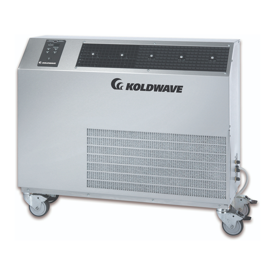
5WK
Water-Cooled Portable
Air Conditioning and
Heat Pump
Installation, Operating
and Maintenance Manual
Model No._______________________ Serial No._______________________________
Table of Contents:
General Information ..............................................................................2
Installation Instructions ........................................................................3
Specification and Electrical Data ...........................................................4
Service ................................................................................................. 5-8
Unit Operation ................................................................................. 9-10
Inspection & Repair of Electrical System ............................................12
Inspection & Repair of Refrigerant system .........................................12
Preventative Maintenance ....................................................................12
Electrical Diagram ......................................................................... 13-15
Trouble Shooting Guide ................................................................. 16-23
260 North Elm St.
Westfield, MA 01085
Phone: 413.564.5520
Fax: 413.564.5815
www.koldwave.com
IOM5WK-4
K5KW-IOM
Advertisement
Table of Contents

Subscribe to Our Youtube Channel
Related Manuals for Koldwave 5WK07


Summary of Contents for Koldwave 5WK07
-
Page 1: Table Of Contents
Inspection & Repair of Refrigerant system .........12 Specification and Electrical Data ............4 Preventative Maintenance ..............12 Service ....................5-8 Electrical Diagram ................. 13-15 Unit Operation ................. 9-10 Trouble Shooting Guide ..............16-23 260 North Elm St. Westfield, MA 01085 Phone: 413.564.5520 Fax: 413.564.5815 www.koldwave.com... -
Page 2: General Information
INSTALLER’S RESPONSIBILITY: This equipment has been valve housed in one cabinet. All Koldwave units, except the run tested and inspected thoroughly. It has been shipped 5WK07, are provided with heavy-duty casters. Two swiv- free of defects from our factory. -
Page 3: Installation Instructions
Installation Instructions Some Koldwave units are equipped with LCDI device service IMPORTANT: Following the installation and preventative cords. The service cords employed have plug configurations maintenance instructions can extend the length of service and receptacle requirements as shown in Figure 1. Modifica- you receive from your Koldwave unit. -
Page 4: Specification And Electrical Data
Specification and Electrical Data Figure 4 DEL NUMBER MODEL NUMBER 5WK07 5WK07 5WK14 5WK14 5WK18 5WK18 ELECTRIC DATA ELECTRIC DATA Voltage/Phase/Hertz Voltage/Phase/Hertz 115/1/60 115/1/60 115/1/60 115/1/60 230/1/60 230/1/60 Amperage Amperage 11.6 11.6 Fuse Size (Amps) Fuse Size (Amps) Watts Watts... -
Page 5: Service
Service The Koldwave unit has removable panels to provide full service accessibility. Figure 5 - 5WK07 Unit Construction Side View Figure 6 - 5WK07 Unit Construction Back View Blower Motor Condensate Pump Condenser Drain Outlet... - Page 6 Figure 7 - 5WK14 Unit Construction Front View Condenser Coil Figure 8 - 5WK14 Unit Construction Back View...
- Page 7 Figure 9 - 5WK18/26 Unit Construction Back View...
- Page 8 Figure 10 - 5WK18/26 Unit Construction Side View...
-
Page 9: Unit Operation
Change from °F to °C: Hold the COOL HIGH button for 5 seconds and the display will switch from Farenheit to Celsius or vice versa. Unit Off: Depress the OFF button at any time to turn the SYSTEM MODE off. The unit will remain idle until further instruction. - Page 10 Auto Reset High Pump Switch: If the High Pump Switch trips, “H.P” is displayed until the failure clears. Once failure clears, the unit goes back to the previous mode it was in before the trip. If the High Pump Switch trips 3 times within 30 minutes, the unit is locked out, forced into the Off position, and “E.H”...
- Page 11 Figure 11 AC Unit Control Panel Figure 12 Optional Remote Control Figure 10 Heat Pump Unit Control Panel...
-
Page 12: Inspection & Repair Of Electrical System
Preventative Maintenance PSI of compressed air or nitrogen applied to the Water In (mid- Your Koldwave portable spot cooler has been designed to give dle) connection. To do this turn the unit off. Shut off the water maximum performance and reliability with minimum mainte- supply. -
Page 13: Electrical Diagram
Electrical Diagram Figure 13 - 5WK07-115/1 PH... - Page 14 Electrical Diagram...
-
Page 15: Electrical Diagram
Electrical Diagram Figure 15 - 5WK18 AND 5WK26 - 208-230/1 PH... -
Page 16: Trouble Shooting Guide
Trouble Shooting Guide Before troubleshooting this system, read this manual to determine electrical power and installation requirements to allow the spot cooler to perform at its maximum efficiency. Refer to general description, wiring diagrams and photographs to get an understanding of how the unit functions. Service other than routine maintenance should be performed only by a qualified refrigeration service person. - Page 17 Trouble Shooting Guide Continued GENERAL TROUBLESHOOTING Abnormal noise. 1 Loose compressor mounting nuts. 1 Tighten. 2 Defective, improper or worn rubber 2 Replace grommets. grommets on the compressor mounting bolts. 3 Copper tube vibrating. 3 Adjust by bending slightly to firm position. Separate tubes touching cabinet or each other.
-
Page 18: General Troubleshooting
Trouble Shooting Guide Continued GENERAL TROUBLESHOOTING Circuit breaker or fuses blowing 1 Low voltage to unit. 1 Check power supply for proper voltage at unit plus or minus 10% of rated nameplate voltage. 2 Compressor short cycles 2 See section on compressor troubleshooting. 3 Defective wiring or connection. - Page 19 Trouble Shooting Guide Continued COMPRESSOR TROUBLESHOOTING Compressor tries to start when t- 1 Low voltage 1 Check voltage at wall outlet. Must be within stat closes, but cuts out on 10% of nameplate rating voltage. overload; finally starts after several attempts 2 Compressor capacitor incorrect or defective 2 Check capacitance and replace if necessary.
- Page 20 Trouble Shooting Guide Continued COMPRESSOR TROUBLESHOOTING Compressor short cycles 1 Low voltage 1 Check voltage at wall outlet. Must be within 10% of nameplate rating voltage. 2 Capacitor incorrect or defective 2 Check capacitance and replace if necessary. 3 Compressor motor defective 3 Replace compressor 4 Wiring incorrect or defective 4 Tug on wires to see if they will separate from connections.
- Page 21 Trouble Shooting Guide Continued HEAD PRESSURE TROUBLESHOOTING Too high 1 Condenser dirty, clogged or restricted. 1 Replace condenser coil. 2 Air or non-condensable gases in system 2 Recover refrigerant, install filter/dryer, evacuate system and weigh in proper charge of virgin refrigerant. 3 Fan blade or motor defective 3 Check and replace.
- Page 22 Koldwave warrants all Koldwave products to be free from defects in materials or workmanship, under normal use and service, for a period of twelve (24) months from date of shipment from the factory. Koldwave further warrants that the refrigeration compressor will be free from defects in materials and workmanship for (3) years from date of shipment from the factory.
Need help?
Do you have a question about the 5WK07 and is the answer not in the manual?
Questions and answers