Table of Contents
Advertisement
INSTRUCTION MANUAL
IM441-U v0.7
EMM-R4h
EMM-µ4h
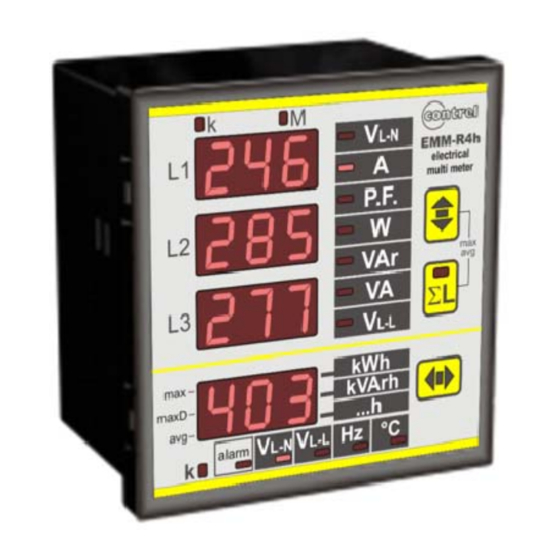
GENERALITY
These digital multimeters series allow to monitor all the electrical parameters
present on a distribution line. The local display of 30 electrical parameters is
carried out by 4 display with red LED guaranteeing a good and contemporary
reading of more measures. A simple front panel completes the intuitive
selection of several electrical parameters, with a great quantity of information.
These instruments, over of the instantaneous measures, display the
maximum peak of the main parameters (maximum peak and maximum
demand).
The presence of the serial port communication EIA485 (option) allows the
Connection in network of more instruments to realize centralized measure
networks.
These multimeters replace in a unique device, all the functions of voltmeters,
ammeters, energy meters, cosphimeters, wattmeters, varmeters, frequency
meters permitting a great economic saving, a reduction of dimension and the
wiring energy and a simplification in the purchase and management of the
instruments because this is a model usable at all of need of local measure in
the electrical panel, machine, etc.
OPTIONS
- internal CT
- digital output (in alternative to the serial port)
- serial port (in alternative to the digital output)
- power supply different from standard version
- current input 1A
MEASURED PARAMETERS
parameters
phase and three phase voltages
phase to phase and three phase system voltages
phase and three phase currents
phase and three phase power factors
phase and three phase active powers
phase and three phase system reactive powers
phase and three-phase system apparent powers
frequency
temperature
three phase system active energy
three phase system reactive energy
three phase system apparent energy
hours counter
peak value (maximums):
maximum phase voltages
maximum phase currents
maximum three-phase powers
maximum average phase currents (maximum demand)
maximum average three-phase powers (maximum demand)
average phase currents
average three-phase powers
EMM-R4h
EMM-μ4h
ELECTRICAL MULTIFUNCTION METER
[V-kV]
[V-kV]
[A-kA]
[W-kW-MW]
[VAr-kVAr-MVAr]
[VA-kVA-MVA]
[Hz]
[°C]
[kWh]
[kVArh]
[kVAh]
[hr]
[V-kV]
[A-kA]
[W-VAr-VA (k-M)]
[A-kA]
[W-VAr-VA (k-M)]
[A-kA]
[W-VAr-VA (k-M)]
instruction manual
unit of measurement
V
L1-N
V
L1-L2
A
L1
PF
W
VAr
VA
Hz
T
kWh
kVArh
kVAh
h
V
L1-N max
A
L1 max
W
I
L1 max (avg)
W
A
L1 avg
W
IM441-U v0.7
initial identification
V
V
L2-N
L3-N
V
V
L2-L3
L3-L1
A
A
L2
L3
PF
PF
L1
L2
L3
W
W
L1
L2
L3
VAr
VAr
L1
L2
L3
VA
VA
L1
L2
L3
L3
V
L2-N max
A
L2 max
VAr
max
max
I
L2 max (avg)
VAr
max (avg)
max (avg)
A
L2 avg
VAr
avg
avg
V
L-N
V
L-L
A
PF
W
VAr
VA
V
L3-N max
A
L3 max
VA
max
I
L3 max (avg)
VA
max (avg)
A
L3 avg
VA
avg
pag. 1
Advertisement
Table of Contents

Related Manuals for Contrel EMM-R4H


Summary of Contents for Contrel EMM-R4H
- Page 1 INSTRUCTION MANUAL IM441-U v0.7 EMM-R4h ELECTRICAL MULTIFUNCTION METER EMM-µ4h GENERALITY These digital multimeters series allow to monitor all the electrical parameters present on a distribution line. The local display of 30 electrical parameters is carried out by 4 display with red LED guaranteeing a good and contemporary reading of more measures.
- Page 2 For example for application on single phase 230V will need the L3-N / 230V. while for applications in medium voltage (for example using external voltage transformer 15 / 0.1 kV phase to phase) will need the version L2-L3 / 110V. EMM-R4h EMM-µ4h...
- Page 3 3 wires (without neutral or with neutral not supplied) the N terminal must not be conneccted LOAD INSERTION ON THREE PHASE LINE WITH 4 WIRES AND 3 VT LOAD EMM-R4h EMM-μ4h instruction manual IM441-U v0.7 pag. 3...
- Page 4 THREE PHASE LINE WITH 2CT (AARON insertion) LOAD VOLTAGE INSERTION ON THREE PHASE LINE WITH 3 WIRES AND 2 VT This voltage insertion is possible only with the version with internal CT (-t suffix). LOAD EMM-R4h EMM-μ4h instruction manual IM441-U v0.7 pag. 4...
- Page 5 3 wires (without neutral or with neutral not supplied) the N terminal must not be connected LOAD INSERTION ON SINGLE PHASE Only for models with power supply phase-neutral (Vaux L3-N) LOAD EMM-R4h EMM-μ4h instruction manual IM441-U v0.7 pag. 5...
- Page 6 Pressing the A key on the G display will appear the message SET that will remain always displayed during the set of each parameter to highlight the SeTUp phase in running. The set values will be keep also in absence of auxiliary power supply. EMM-R4h EMM-μ4h instruction manual IM441-U v0.7...
- Page 7 8data 1stop-even parity 8.1 paR ODD (version with serial output) bit: 8data 1stop-odd parity SET PAS Increase Set Password OFF - 0002 ÷ 9999 Decrease Confirm and end of general settings EMM-R4h EMM-μ4h instruction manual IM441-U v0.7 pag. 7...
- Page 8 C key to decrease and B to increase the rate. The values settable are: - 19.2 => 19200 baud - 9.60 => 9600 baud - 4.80 => 4800 baud - 2.40 => 2400 baud Press A to confirm the value displayed. EMM-R4h EMM-μ4h instruction manual IM441-U v0.7 pag. 8...
- Page 9 (ALR LO). The activation of the alarm output will come after some seconds of delay set(ALR DL). In the REMOTE mode, the output status will be decided from the status of the correspondent MODBUS register (see protocol modbus manual for EMM). EMM-R4h EMM-μ4h instruction manual IM441-U v0.7...
- Page 10 ALR DLY and the value expressed in seconds (range 1÷900). The modification of the value is done in the same way of the threshold set. With the confirmation (A key) the set is complete. The programming will be referred to the digital output indicated on G display (DO1 o DO2). EMM-R4h EMM-μ4h instruction manual IM441-U v0.7...
- Page 11 Digital output Functioning for Alarm delay exceeding or dropping delay t < delay by the band defined by maximum and Threshol d HI minimum threshold Hysteresis HI Hysteresis LO Threshol d LO EMM-R4h EMM-μ4h instruction manual IM441-U v0.7 pag. 11...
- Page 12 R and the number of the instrument that is in communication while if the instrument transmits data, it displays the letter T. VARIABLE LIST three-phase voltage three-phase current three-phase power factor active power reactive power apparent power phase to phase voltage frequency T°C temperature EMM-R4h EMM-μ4h instruction manual IM441-U v0.7 pag. 12...
- Page 13 L1 display will indicate the first 3 digits, the display L2 the seconds 3 digits and the L3 display the last 3. For example if: L1=000, L2=028, L3=53.2 the reading is 2853.2 kWh. EMM-R4h EMM-μ4h instruction manual IM441-U v0.7...
- Page 14 In some application where the secondary is connected to other instruments apart from the EMM multimeter, some problems could happen concerning the typology of the amperometric inputs. If there are some problem call the assistance service. EMM-R4h EMM-μ4h instruction manual IM441-U v0.7...
- Page 15 Max 32 EMM; max 1200 meters LINE 2 R=120 CONNECTION WITH SHIELDED CABLE RS485 RS232 For other information on the serial line it’s better to see the manual of EMI1 serial converter. DIMENSIONS EMM-R4h cut panel electrical multi meter P.F. L kVArh maxD ...h...
- Page 16 IP52 frontal - IP20 enclosure and terminals - weight: about 0,5 kg connections with screw terminals for cable 2,5 mm enclosure thermoplastic self-extinguishing EMM-R4h: flush mounting DIN 96x96mm, depth 56mm EMM-µ4h: flush mounting DIN 72x72mm, depth 95mm environmental working temperature: -10÷60°C;...
Need help?
Do you have a question about the EMM-R4H and is the answer not in the manual?
Questions and answers