Table of Contents
Advertisement
Quick Links
SAFETY-RELATED COMPONENT WARNING!!
COMPONENTS IDENTIFIED BY MARK
SCHEMATIC DIAGRAM AND IN THE PARTS LIST ARE
CRITICAL FOR RISK OF FIRE AND ELECTRIC SHOCK.
REPLACE THESE COMPONENTS WITH ONKYO
PARTS WHOSE PART NUMBERS APPEAR AS SHOWN
IN THIS MANUAL.
MAKE LEAKAGE-CURRENT OR RESISTANCE
MEASUREMENTS TO DETERMINE THAT EXPOSED
PARTS ARE ACCEPTABLY INSULATED FROM THE
SUPPLY CIRCUIT BEFORE RETURNING THE
APPLIANCE TO THE CUSTOMER.
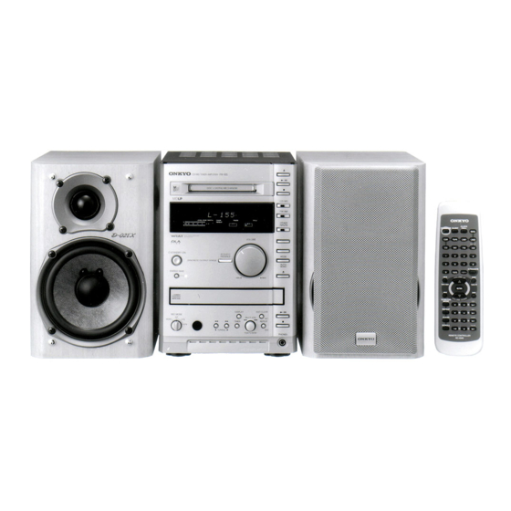
CD/MD TUNER AMPLIFIER
MODEL FR-155
Silver model
UDT
120V AC, 60Hz
220 -230V AC, 50/60Hz
UGT
TABLE OF CONTENTS
ON THE
Specifications -----------------------------------------------------------
Caution on replacement of optical pickup ---------------------------
Protection of eyes from laser beam during servicing ---------------
Laser Warning Label----------------------------------------------------
Service procedures -----------------------------------------------------
Front panel view --------------------------------------------------------
Connecting to Other Components------------------------------------
Remote controller -------------------------------------------------------
Setting the day of the Week and the Time----------------------------
IC Block diagram and descriptions -----------------------------------
Microprocessor Connection Diagram---------------------------------
Microprocessor Terminal Description--------------------------------
Operation of the Microprocessor--------------------------------------
MD Mechanism Exploded view-------------------------------------
MD Mechanism Disassembly ----------------------------------------
MD Mechanism Reassembly ----------------------------------------
MD Adjustment Procedures ------------------------------------------
MD Mount View / Messages--------------------------------------------
CD Mechanism Exploded View ---------------------------------------
CD Adjustment Procdedure-------------------------------------------
Clock Adjustment Procdedure-----------------------------------------
Handling of Pickup-----------------------------------------------------
Chassis Exploded View Parts List------------------------------------
Chassis Exploded View ------------------------------------------------
Block Diagram----------------------------------------------------------
Block Diagram (Power Supply Section)------------------------------
Schematic Diagram (Amplifire Section)-----------------------------
Printed Circuit Board View 1------------------------------------------
Schematic Diagram (CD&Microprocessor Section)----------------
Printed Circuit Board View 2------------------------------------------
Schematic Diagram (Power Supply Section)-----------------------
Printed Circuit Board View 3------------------------------------------
Printed Circuit Board View Parts List--------------------------------
Wiring View-------------------------------------------------------------
Packing View Parts List------------------------------------------------
FR-155
Ref. No. 3662
092000
2
2
3
3
3
4
5
6
6
7
15
16
17
18~19
20,21
22
23~25
26
27,28
29
30
31
32
33
35
37
39
41
43
45
47
49
51~54
55
57
Advertisement
Table of Contents

Related Manuals for Onkyo FR-155


Summary of Contents for Onkyo FR-155
-
Page 1: Table Of Contents
CRITICAL FOR RISK OF FIRE AND ELECTRIC SHOCK. Setting the day of the Week and the Time---------------------------- IC Block diagram and descriptions ----------------------------------- REPLACE THESE COMPONENTS WITH ONKYO Microprocessor Connection Diagram--------------------------------- PARTS WHOSE PART NUMBERS APPEAR AS SHOWN Microprocessor Terminal Description-------------------------------- IN THIS MANUAL. -
Page 2: Specifications
FR-155 SPECIFICATIONS General MD recorder Power supply AC 220-230 V, 50/60 Hz Signal readout system Optical non-contact AC 120 V, 60 Hz Recording time 320 minutes maximum Power consumption 63 W (220-230 V, 50/60 Hz) (at LP4 mode) 82 W (120 V, 60 Hz) -
Page 3: Protection Of Eyes From Laser Beam During Servicing
FR-155 PROTECTION OF EYES FROM LASER BEAM DURING SERVICING This set employs a laser. Therefore, be sure to follow carefully Laser Diode Properties the instructions below when servicing. Material: GaAS/GaALAs Wavelength: 780nm WARNING!! Laser output: max. 0.5mW* SERVICE WARNING : DO NOT APPROACH THE Emission Duration: continuous LASER EXIT WITH THE EYE TOO CLOSELY. -
Page 4: Front Panel View
FR-155 FRONT PANEL VIEW button CD / MD TUNER AMPLIFIER button MD disc slot DISC LOADING MECHANISM button CD / MD CD/MD button FM /AM FM/AM button VOLUME control OTHER INPUTS OTHER INPUTS button WIDE RANGE AMPLIFIER TECHNOLOGY VOLUME REC button... -
Page 5: Connecting To Other Components
LINE-2 jacks. The FR-155 has a SUBWOOFER PRE OUT jack. Connect DVD player an active subwoofer (a subwoofer that contains an amplifier), or connect an amplifier to the FR-155, then connect a non- Analog active subwoofer to the amplifier. Digital... -
Page 6: Remote Controller
MODE MODE button CD operation buttons REPEAT REPEAT button MD operation buttons CLEAR CLEAR button Operation buttons for an Onkyo CDR TAPE SCROLL Operation buttons for an SCROLL button Onkyo stereo cassette tape dec k REMOTE CONTROLLER RC-434S SETTING THE DAY OF THE WEEK AND THE TIME y. -
Page 7: Ic Block Diagram And Descriptions
FR-155 I C BLOCK DIAGRAM AND DESCRIPTIONS Q401:TC9273N-004 (Analog function switch) Q103,Q181:TA7291S (Motor driver) Vref OUT1 OUT2 PROTECTOR INPUT OUTPUT OUT1 OUT2 MODE STOP CW/CCW CCW/SW LEVEL SHIFT AND SHIFT REGISTER BRAKE CCW : Counter clockwise direction CW : Clockwise direction... - Page 8 FR-155 Q351:CXD2589Q (CD Digital Signal Processor) Block Diagram 51 25 26 27 28 47 49 54 56 50 39 41 55 40 42 44 62 TES1 TEST Clock Error XRST Generator Corrector RMUT Interface demodurator LMUT Serial-In Interface ASYI Asymmetry...
- Page 9 FR-155 PIN Description No. Symbol Description No. Symbol Description D/A interface. Bit clock output. — Left-channel zero detection flag. D/A interface. Bit clock input. LMUT BCKI — RMUT Right-channel zero detection flag. Power supply (+5V). SQSO readout clock input. —...
- Page 10 FR-155 Q101:CXA1992BR (RF Signal Processing Servo Amplifier) Block Diagram RF SUMMING AMP PD1 IV PD2 IV FE - BIAS SENS2 SENS1 LASER POWER CONTROL F IV AMP C.OUT FE AMP E IV AMP DFCT XRST LEVEL S DATA FO.BIAS MIRR WINDOW COMP.
- Page 11 FR-155 Pin Description No. Symbol Description No. Symbol Description Focus error amplifier output. 26 SENS2 Outputs DFCT2, MIRR, BALL, TGL, FOL, and Connected internally to the window comparator input others according to the command from the CPU. for bias adjustment.
- Page 12 FR-155 Q102:LA6541D (CD 4-channel BTL Driver ) Pin No. Pin Name Description (Function) Power supply (shorted with pin 30) Mute ON/OFF control for all BTL AMP outputs BTL AMP 1 input Vref Mute BTL AMP 1 input (for gain control)
- Page 13 FR-155 Q752:M66004F (FL Tube Driver) Display code CG ROM register SEG00 (35bit 160) Segment output SEG26 Segment code write output circuit Chip select input SEG27 Serial Shift clock receive input circuit CG RAM Serial data SDATA (35bit 16) Code /...
- Page 14 FR-155 Q751:BJ780GNK(FL Tube) Col-1 Col-2 SLEEP SOURCE C D TIMER ONCE W.DAY W.END S.BASS MUTING LEVEL - SYNC DIGITAL CHAIN DISC TRACK ELAPSED REMAIN TITLE REPEAT RDS MONO AUTO STEREO TUNED 1 TR MEMORY - 40 - 20 - 10...
-
Page 15: Microprocessor Connection Diagram
MICROPROCESSOR CONNECTION DIAGRAM Q371 TC74HCT00AF Q751 BUFFER FL TUBE Q372 1G 14G Q372 P1 P36 DIGITAL TC7WU04FU OPTICAL MD MECHA BUFFER Q372 AUX-MD IN Q752 1 12,60 64 A MUTE 23 31,33 59 GRID MD OUT M66004F REC MODE SW SEGMENT Q401 Q171... -
Page 16: Microprocessor Terminal Description
MICROPROCESSOR TERMINAL DESCRIPTION Q701:MPD780058GC-8BT Description Description Function Function ROTEN2 Pulse input pin 1 from rotary encoder. CDMUT Muting signal output pin for CD analog signal. ROTEN1 Pulse input pin 2 from rotary encoder. SELMUT Muting signal output pin for audio section. FLRESET Reset signal output pin for FL driver IC(M66004) APLED... -
Page 17: Operation Of The Microprocessor
FR-155 OPERATION OF THE MICROPROCESSOR OPERATION OF THE MICROPROCESSOR TERMINAL LINKED WITH THE ENERGY SAVE FUNCTION In the energy save mode (including the preparation period). only the STANDBY/ON button and the ENERGY SAVE button can be operated. 60 seconds after the energy save is operated. the microprocessor is turned to the energy save mode. - Page 18 FR-155 MD MECHANISM EXPLODED VIEW(1) (KMK-260BCN) SW1-SW4 Parts which have been described to the NOTE column of the undermentioned part list as NSP are not supplied. Ref. No. Part No. Description NOTE Ref. No. Part No. Description NOTE Motor Plate ass'y...
-
Page 19: Md Mechanism Exploded View
FR-155 MD MECHANISM EXPLODED VIEW(2) (KMK-260BCN) Parts which have been described to the NOTE column of the undermentioned part list as NSP are not supplied. Ref. No. Part No. Description NOTE Ref. No. Part No. Description NOTE L-SW PWB Screw (+P1.4 3.5 Type3) -
Page 20: Md Mechanism Disassembly
FR-155 MD MECHANISM DISASSEMBLY Remove the case (lower)(27) by unscrewing the four MD Mechanism KMK-260BCN screws (step)(13). Screw(step) Screw(step) Screw(step) Screw(step) Remove the two special screws(31)used to Remove the spring(Z3) from the door MD(Z3). fix the loading motor. Special Screw(31) - Page 21 FR-155 MD MECHANISM DISASSEMBLY Short circuit with solder the short land on the pick-up unit(74). Remove the gear(18). [NOTE] Do not do the work of before completing the work of short land Remove the gear(18) Disconnect the four flexible flat cables.
-
Page 22: Md Mechanism Reassembly
FR-155 MD MECHANISM DISASSEMBLY Remove the screw(51) used to fix the guide shaft(61). Remove the pick-up unit(74). Guide shaft (61) Pick-up unit(74) Lead holder B(72) Screw(51) Loosen the screw(51) used to fix the guide shaft (61). Pick-up unit(74) is exchanged. -
Page 23: Test Mode
FR-155 MD RECORDING ADJUSTMENT PROCEDURES 1.TEST MODE 1. Precaution for using the test mode It is necessary to adjust in the test mode. Make clear the test mode after ending the adjustment. In the following, the rotation of the disc dose not stop even if EJECT key is pushed. - Page 24 FR-155 2. PRECAUTIONS 1. Precaution for chacking laser emmition from the laser diode. Never look into the laser diode when checking the laser emmition durring adjustments. During so may cause loss of your eyesight. 2. Adjustment information. Replacement pickup Replacement PC board Replacement other parts...
- Page 25 FR-155 3. Laser power check [Procedure] Operation Display 1. Install the laser power meter on the objective lens 2. Enter the test mode select "LDPWR CHECK" LD PWR CHECK 3. Press the MULTI JOG knob. LD 0.9mW $ # # 4.
-
Page 26: Md Mount View / Messages
FR-155 MD MOUNT VIEW MD Mount (side B) MD Mount (side A) CN101 CN105 (to pickup unit) (to D-SW PC board) IC121 IC201 D101 IC101 CN103 IC152 CXD2662R CXP740010 CN104 CXA2523AR BA5984 (to MD over write head) IC125 MSM51V4400D Loading motor... - Page 27 FR-155 CD MECHANISM EXPLODED VIEW (1)
-
Page 28: Cd Mechanism Exploded View
FR-155 CD MECHANISM EXPLODED VIEW(2) (NCD-170S Pickup drive unit) The mechanical parts with no part number in the exploded views are not supplied. Ref. No. Part No. Description X2625-984-1 Motor chassis ass'y X2625-769-1 Motor gear ass'y 2656-908-01 Sled shaft 2625-188-02... -
Page 29: Cd Adjustment Procdedure
FR-155 CD ADJUSTMENT PROCEDURES Preparation Set the trimming resistors R123 to center. Focus gain adjustment 1. Set the output of the audio oscillator to 1kHz and 1 1.5Vp-p. 2. Connect the oscilloscope and audio oscillator as shown below. (Refer to Fig-1) 3. - Page 30 FR-155 ADJUSTMENT OF CLOCK FREQUENCY 1. Remove the top cover. 2. Connect the frequency counter to the terminal P702 on the CD & microprocessor PC board (NADG-6939) 3. While hold down CD STOP key, press STANDBY/ON key to set the test mode.
-
Page 31: Handling Of Pickup
FR-155 HANDLING OF OPTICAL PICKUP The laser diode in the optical pickup block is so sensitive to static electricity,surge current and etc. That the components are liable to be broken down or its reliability remarkably deteriorated. During repair,carefully take the following precautions. -
Page 32: Chassis Exploded View Parts List
FR-155 CHASSIS EXPLODED VIEW PARTS LIST DESCRIPTION DESCRIPTION REF. NO. PART NO. REF. NO. PART NO. Front bracket 2203383 or 2SC3851-O or 27111174A Q557 Knob, AOC 28325814 2203384 2SC3851-Y, Transistor , Q558 Knob, AT 28325815 2203393 or 2SA1488-O or Q559... -
Page 33: Chassis Exploded View
FR-155 CHASSIS EXPLODED VIEW P391C P203C P102C P103C P250C P404C P901 (DT type) T901 F901 P010C Q557,Q558 P101C P901 (GT type) P752C Q559,Q560... -
Page 34: Block Diagram
FR-155 FR-155 BLOCK DIAGRAM TUNER UNIT SELECTOR CIRCUIT PC BOARD ACOUSTIC CIRCUIT PC BOARD NAAF-6934 TFCE1E512A NASW-6937 POWER AMPLIFIER CIRCUIT P250 PC BOARD NAAF-6930 SPEAKER TERMINAL PC BOARD STEREO Q441 NAETC-6932 ACOUSTIC L SIGNAL TUNER-R Q254 ANTENNA PRESENCE R441 BUFFER... -
Page 35: Block Diagram (Power Supply Section)
FR-155 BLOCK DIAGRAM (POWER SUPPLY SECTION) POWER SUPPLY CIRCUIT PC BOARD NAPS-6928 Q911 Q912 +12 V OUT IN +5 V P920B REGULATOR REGULATOR to CD Microprocessor & CD Circuit PC Board +5 V NADG-6933 PRIMARY CIRCUIT PC BOARD +12 V... -
Page 36: Schematic Diagram (Amplifire Section)
FR-155 FR-155 SCHEMATIC DIAGRAM (AMPLIFIER SECTION) -
Page 37: Printed Circuit Board View 1
FR-155 PRINTED CIRCUIT BOARD VIEW 1 POWER AMPLIFIER CIRCUIT PC BOARD (NAAF-6930) SELECTOR CIRCUIT PC BOARD (NASW-6937) ACOUSTIC CIRCUIT PC BOARD (NAAF-6934) PRIMARY CIRCUIT PC BOARD ( NAPS-6929) -
Page 38: Schematic Diagram (Cd&Microprocessor Section)
FR-155 FR-155 SCHEMATIC DIAGRAM(CD&MICROPROSSEOR SECTION) -
Page 39: Printed Circuit Board View 2
FR-155 PRINTED CIRCUIT BOARD VIEW 2 SPEAKER TERMINAL MICROPROCESSOR & CD CIRCUIT PC BOARD (NADG-6933) PC BOARD (NAETC-6932) CD CONNECTOR PC BOARD (NAETC-6939) -
Page 40: Schematic Diagram (Power Supply Section)
FR-155 FR-155 FR-155 SCHEMATIC DIAGRAM (DISPLAY &POWER SUPPLY SECTION) -
Page 41: Printed Circuit Board View 3
FR-155 PRINTED CIRCUIT BOARD VIEW 3 DISPLAY CIRCUIT PC BOARD (NADIS-6935) POWER SUPPLY CIRCUIT PC BOARD (NAPS-6928) CONTROL SWITCH PC BOARD (NASW-6936) HEADPHONE JACK PC BOARD (NAETC-7034) -
Page 42: Printed Circuit Board View Parts List
FR-155 FR-155 PRINTED CIRCUIT BOARD PARTS LIST POWER SUPPLY CIRCUIT PC BOARD(NAPS-6928-1B/1C) PRIMARY CIRCUIT PC BOARD(NAPS-6929-1B/1C) CIRCUIT NO. PART NO. DESCRIPTION CIRCUIT NO. PART NO. DESCRIPTION Transistors Q911 222780125JRC or NJM78M12FA or Q501-Q504 2211733 2SC1845-E 222780125NEC MPC78M12HF Q505-Q508 2213284 2SC1740S-R... - Page 43 FR-155 POWER AMPLIFIER CIRCUIT PC BOARD(NAAF-6930-1B/1C) MICROPROCESSOR AND CD CIRCUIT PC BOARD (NADG-6933-1B/1C) PART NO. DESCRIPTION CIRCUIT NO. DESCRIPTION CIRCUIT NO. PART NO. Transistors 22241499R3 CXA1992BR Q901,Q902 DTC123JS Q101 2213640 22241247 LA6541D Diodes Q102 TA7291S 1SS133 or Q103,Q181 22240239 D501,D502...
- Page 44 ACOUSTIC CIRCUIT PC BOARD (NAAF-6934-1B/1C) CIRCUIT NO. PART NO. DESCRIPTION PART NO. DESCRIPTION CIRCUIT NO. Capacitors C101,C102 355721019 F, 6.3 V, Elect. 22240583R2 or TC51832FL-10 or Q441,Q442 C103 374722234 0.022 F 5 %, 50 V, Plastic 22241383R2 NJM4565M-D C104,C105,C115 374721034 0.01 F 5 %, 50 V, Plastic 22240798 TC9162AN...
- Page 45 FR-155 DISPLAY CIRCUIT PC BOARD (NADIS-6935-1B/1C) CD CONNECTOR PC BOARD (NAETC-6939-1B/1C) CIRCUIT NO. PART NO. DESCRIPTION CIRCUIT NO. PART NO. DESCRIPTION FL tube Sockets 212211 BJ780GNK Q751 P010 25052483 NSCT-16P2380 P101A 25052249 NSCT-16P2146 Q752 22240685R9 M66004FP HEADPHONE JACK PC BOARD(NAETC-7034-1B/1C)
-
Page 46: Wiring View
FR-155 FR-155 FR-155 WIRING VIEW SELECTOR CIRCUIT PC BOARD P250 TUNER UNIT (NASW-6937) STEREO POWER AMPLIFIER SPEAKER TERMINAL CIRCUIT PC BOARD P404A P404B TUNER-R PC BOARD (NAAF-6930) TUNER-L TUNER-L (NAETC-6932) TUNER-L ANTENNA TUNER-R TUNER-R DET OUT +12 V JL501A JL501B... -
Page 47: Packing View Parts List
FR-155 PACKING VIEW PACKING VIEW PARTS LIST Ref. No. Part No. Description 29091932A 29091933A Pad, S Pad, H 29091934A 29095864 Sheet, 800*600 29110149 Tape 29110141 Tape, W50L100 282301 Staple Polybag, 350*250 29100097-1A 29362709 Label, EAN 29053623 Carton 24140434 RC-434S, Remote controller... - Page 48 Sales & Product Planning Div. : 2-1, Nisshin-cho, Neyagawa-shi, OSAKA 572-8540, JAPAN Tel: 072-831-8111 Fax: 072-833-5222 ONKYO U.S.A. CORPORATION 18 Park Way, Upper Saddle River, NJ 07458, U.S.A. Tel: 201-785-2600 Fax: 201-758-2650 E-mail: onkyo@onkyousa.com ONKYO EUROPE ELECTRONICS GmbH Industriestrasse 20, 82110 Germering, GERMANY Tel: 089-849-320 Fax: 089-849-3265 E-mail: info@onkyo.de...
Need help?
Do you have a question about the FR-155 and is the answer not in the manual?
Questions and answers