Table of Contents
Advertisement
Advertisement
Table of Contents

Related Manuals for Accurate Locators XL16 IMAGER


Summary of Contents for Accurate Locators XL16 IMAGER
- Page 2 XL16 IMAGER PRO SERIES User’s Guide Copyright © 2010 Accurate Locators Inc. All rights reserved. Duplication of this manual is strictly prohibited in either print, electronic, Or any other media without expressed written consent from Accurate Locators Inc. - 2 -...
-
Page 3: Table Of Contents
Table of Contents Introduction Existing Potential Method (USA) • What EM Measures • Magnetic Surveying • Principles of Magnetics Packaging Contents Quick Start Guide 10-11 Ground Balance Technique Grid Pattern Scan 13-14 Connecting Control Unit Software Introduction 16-24 • Basic Software Functions Software Keyboard Shortcuts Analysis of Scanned Data 26-28... -
Page 4: Introduction
The XL16 IMAGER works on the principle of detecting electromagnetic field changes that are emitted from the Earth. With the XL16 IMAGER, there is no need to transmit a signal into the earth, because of the existing signals that are already present in the earth. The XL16 IMAGER has very sensitive broadband receivers, enabling it to receive electromagnetic and magnetic signals. - Page 5 SCREEN SHOT OF THE XL16 IMAGER PRO IN ACTION You are seeing a screen shot from the new XL-16 IMAGER USA Pro Series. We have enhanced the imaging 16x times the average with increased data speed; producing higher resolution and more accurate detection of targets.
- Page 6 The XL16 IMAGER Pro has a special export function for Google Earth maps. Inside the XL-16 IMAGER Pro software scans can be exported to Google maps as a ground overlay (KML). It converts the scan either to an image with GPS references or remaps the entire scan point by point into Google Earth.
-
Page 7: Existing Potential Method (Usa)
AC/DC and frequency to map potentials, we can map fields of interest. These rapid changing signals are amplified and analyzed by the software. The XL16 IMAGER allows for the rapid collection and interpretation of large quantities of data, making it a cost effective technique. -
Page 8: Principles Of Magnetics
Principles of Magnetics The earth’s geomagnetic field has three principal components: the main field itself, an external field and local perturbations superimposed on the main field. Caused by processes in the interior of the earth, the main field has a large magnitude which varies slowly over time. -
Page 9: Packaging Contents
1- Thumb Drive with 3D & Pin Pointer 1- 3D Geovision Pin Pointer 2- Detailed instruction manuals 2- Adjustable Handles 1- Accurate Locators Hat w/ light 1- Antenna case 1- 3 year warranty information 1- Field pack (fully assembled) 1- Tech support information... -
Page 10: Quick Start Guide
Normal Grid 1. Make sure that batteries are fully charged (not more than 3 hours for the XL16 IMAGER battery) for both the Laptop computer and the XL16 IMAGER. 2. Ensure that the laptop and the control unit are properly in the Front/Backpack. - Page 11 Important Note: Make sure to have your antenna on the ground and pointed in the direction of the row when you are at the Comments screen do not pick the antenna up until it says connection established (fig.4.1a) (Fig. 4.2) - 11 -...
-
Page 12: Ground Balance Technique
GROUND BALANCE PROCEDURES Before starting a new scan it is recommended to check your readings from your ground balance location Fig. 1 Fig. 2 Fig. 3 Fig. 5 1. Magnetic North to South is your recommended direction of scan within the Northern Hemisphere. It will be the exact opposite if scanning within the Southern Hemisphere. -
Page 13: Grid Pattern Scan
Grid Pattern Let us create a Grid, in this example (Figure 4.3) we will go 14 second long reading on the survey line by 6 Survey lines wide. The grid pattern would look like the one below. Typical scans are a minimum of four or more survey lines. The larger your scan, the more background will be available to find your target. - Page 14 Importance of the Grid Pattern The grid performed is ninety percent of the work. If your grid does not align correctly then the scan that appears on the laptop may not be correct. An example of the grid pattern importance is shown below.
-
Page 15: Connecting Control Unit
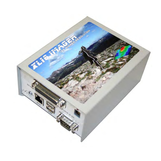
Connecting the XL-16 Imager Pro Control Unit On the face of the Control Unit, several ports can be connected. *The XL-16 Imager does Not utilize all of the port connections. 1. Connect Antenna to the Imaging Port (Com2) 2. Connect the Power connector 3. -
Page 16: Software Introduction
Ninety percent of the work with the XL16 IMAGER is the proper completion of the grid pattern. Afterwards, the software and target identification are quite simple. - Page 17 SCREEN BREAK DOWN TOP BAR SIDE BAR STATUS BAR Top Menu Bar This menu provides full software functionality and quick views. Side Menu Bar The Side Bar contains many of the features Status Bar In the Status Bar information of the Crosshair Point and the name of the file that is open is displayed at all times - 17 -...
- Page 18 Top Menu Bar File – This file has the following options and links to the keyboard shortcuts. In here, you can begin a new scan, open a saved scan, save a scan, or save a scan as a different type of file or name, Export Map Points for topo mapping, Export Map scan for visual over topo mapping export a scan, print a scan, or quit the program.
- Page 19 Toolbars – This function sets which toolbars the user wants to see at the top of the menu. User Defined Rotations – Shows/Hides the toolbar. Pre-Defined Rotations – Shows/Hides the toolbar. Wire frame Mode – This changes the view from a solid to a wire frame.
- Page 20 Highlight Strongest Points – will show the strongest signal values that were recorded during the scan. Highlight Weakest Points – will show the weakest signal values that were recorded during the scan. 2 Color Mode – is a preset filter to highlight the strongest recorded signals in a scan with less change from smaller signals.
- Page 21 (Fig 3.8) Pre-Defined Rotations (Figure 3.8) • Side View – Rotates the scan to a side view. (Figure 3.9) • Reverse Side View – Rotates the scan to the opposite of “Side View” (Figure 4.0) • Oblique View – Rotates the scan to an oblique view. (Figure 4.1) •...
- Page 22 (Fig 4.3) (fig4.4) User Defined 1 -4: Enables the user to pre-program views and angles of scans for easier recognition of targets To set the “User Defined Views” first put the scan in the view that you would like have as a preset then click on the “View”...
- Page 23 HERE IS A BRIEF OVERVIEW OF FUNCTIONS WITH THE GEOSURVEYOR SOFTWARE. Rotation control buttons. With these buttons, you can rotate the scan up, down, left and right. The “C” (Center) button will clear all rotation and set the scan back to a top 2-D View. The two lower buttons rotate the scan on the Z-axis.
- Page 24 Also displayed is the dilution of precision for determining accuracy of GPS signals received. The XL16 IMAGER PRO has a special export function for Google maps. Inside the XL16 IMAGER software scans exported to Google maps as a ground overlay (KML).
-
Page 25: Software Keyboard Shortcuts
Keyboard Shortcuts The Keyboard shortcuts were created for the power user who does not want to rely upon the laptop-pointing device. The following shortcuts are performed by pressing the combination of keys either together, shown with the “+” symbol, or consecutively, shown with the “→”symbol. -
Page 26: Analysis Of Scanned Data
Using a XL16 IMAGER PRO with a 16 sensor antenna; count using the crosshairs over from left to right starting with 1 because the first position gets information. -
Page 27: Analysis Of Scanned Data
Analysis of Scanned Data When initially reviewing a scan, look for greater changes from the average background color. (I.e. Strong reds or blues with the rest of the scan having a single color.) Apply some filtering to the scan to enhance masked areas. (Figure 3.11, Figure 3.12, and Figure 3.13). If the targets are larger, look to see if they have a synthetic or manufactured shape. - Page 28 (Analysis of Scanned Data Cont.) An example scan, Figure 3.14, shows that the first scan point is the strongest difference. This can be caused when first starting and not having the sensor in the correct position in reference to the ground. It is important to be ready when clicking on the go button. A helpful tip;...
-
Page 29: 2-D Measurement Mode
2D Measurement Mode Perhaps one of the most useful tools built into the program is this one. Using the 2D Measurement Mode, you can look at a “Side View” of each individual crosshair. In addition, the rotation functionality is still available in the top right hand corner of the screen. -
Page 30: High's And Low's Signal Identifying
In Figure 3.16, the view here shows a strong rise with a fast fall. In relation to the overall image, the analysis will show a possible anomaly at this position. As previously mentioned, the main characteristics that we are looking for in the scans are the difference in the signal values. -
Page 31: Nulling A High Signal
Nulling a High Signal The process of nulling a signal is quite simple. If the initial scan appears like the one in Figure 3.18, there is a very high signal that is masking most items under it. Nulling a signal means to change the value of a high or low point on the scan to match the background. -
Page 32: Tunnels And Void Locating
Being able to locate tunnels, voids, caverns, sinkholes, etc… is a major function of the XL16 IMAGER PRO. Using EM technology the XL16 IMAGER PRO Sensor Array is able to pick up the signals emitted by a void or tunnel. The following is the proper procedure for locating a tunnel. The grid pattern does change when looking for tunnels or voids. - Page 33 4. The final view will allow you to see where the tunnel begins and where it ends. 5. In Figure 4.9, all of the points of this type of tunnel are explained. 1. Beginning of the tunnel. 2. First lowest signal generated by the tunnel. 3.
-
Page 34: Searching An Area
Searching an Area When searching an area, the first thought is always to do the whole area in one shot. We recommend breaking up the area into smaller pieces if it is a large area (Figure 4.10). For example if the area to be searched is the size of a football field, we suggest cutting it up into several sections so that your scans can be more accurate with less chance of error. -
Page 35: Double-X-Ing Your Target
Double X your Target One of the most commonly asked questions is, “How do I know I’m looking at a real target?” We call this procedure “Double X-ing”. This routine is extremely important, especially with Electromagnetic devices that can see deeper than most detectors. Figure 4.11 is a typical visual example of a found cache. -
Page 36: Determining Approximate Depth Point
Determining Approximate Depth Point First, here is some general info on the cross hairs and data screen. You can both determine depth estimate and size using the Geo Surveyor software. After performing a scan, bring up the scan in the software. Using the purple and black arrows on the left move the crosshairs over your target. - Page 37 Then click view and then click Show Data under Cross hairs. This brings up a window that has the depth in METERS on it as well as the strength or weakness of the target *"Data Value". Numbers before Decimal point are less than 1 meter (3.3 Feet).
-
Page 38: Determining Size Of Target
Example, using a XL16 IMAGER PRO with a 16 sensor, antenna count using the crosshairs over from left to right starting with 1 because the first position gets information (each sensor gets 1 count). -
Page 39: Examples Of Targets
Examples The following examples are a collection of actual targets, from both our dedicated training facilities and scans taken in the field. This is an example of a 55-gallon drum that is buried at our test facility in Oregon. The background is mainly green and yellow while the target (barrel) shows as a red. - Page 40 This is an example scan of clear soil. The soil in this scan is free of any anomalies or surface mineralization. This scan has three targets. All of the targets are buried under 6 inches of concrete. They are shown as the blue from the dug holes in the center of the scan, and Red for the metal content with strong reading.
-
Page 41: Introduction To Geovision Sensor
The all new GEOVISION Professional Series • New processor for faster and greater resolution then previous models. • • 32 times higher resolution then standard Pin Pointer Pro. • • New handle design with compass for easier directional orientation. • •... - Page 42 Ground Balancing and Scan Method USA Geovision Professional Series *Before you connect or disconnect any component make sure to turn off your XL16 IMAGER PRO Control unit first. Failure to follow these instructions will potentially damage your control unit and void your existing warranty.*...
-
Page 43: Xl Usa Geo Pin Pointer
XL-USA Geo Pin-pointer Quick-Start Easy Use Card 1. Turn on control unit power 2. Start laptop computer and start software 3. Make sure antenna and network cables are plugged in 4. Allow a few moments for programs to communicate with one another 5. -
Page 44: Scanning Methods
Scan Method and Samples For depth estimation mark the ground over target (largest Number) then walk away from target until you get "0" reading. Then measure distance to target, that distance will be approximate depth. Repeat several times at different angles of approach to affirm depth estimation. - Page 45 Scans Performed in the Dry Desert Climate at Walking Speed* *wet climates will increase readings - 45 -...
- Page 46 Scans Performed in the Dry Desert Climate at Walking Speed* *wet climates will increase readings - 46 -...
- Page 47 Scans Performed in the Dry Desert Climate at Walking Speed* *wet climates will increase readings - 47 -...
-
Page 48: Common Errors
- 48 -... -
Page 49: Troubleshooting
Troubleshooting Improperly charged batteries cause the #1 reason for errors with the XL16 IMAGER PRO. Please be sure that your batteries are fully charged. The best way to test for fully charged batteries is to use a Multimeter. Q. My laptop screen saver came on and an error window appeared. When I closed the window the software closed, where is my data? A. -
Page 50: Unexploded Ordnances
Unexploded Ordnances What is UXO? UXO, which stands for Unexploded Ordnance, results from the military's use of munitions in training. Military munitions include bullets, bombs, rockets, pyrotechnics, grenades, blasting caps, shells, fuses, pyrotechnic and explosive simulators, and other explosive items. Most military munitions contain some form of propellants, explosives, or pyrotechnic (PEP) mixes to make them function (explode, propel, or produce intense smoke or light) properly. - Page 51 (UXO CONT.) All UXO should be considered extremely dangerous! What types of areas would I encounter UXO? What areas are the most dangerous? Areas that the military uses for weapons training or for testing weapons or munitions are most likely to contain UXO. Signs, like those below, normally mark these areas, which are normally on military installations or bases.
-
Page 52: Alternative Power Supply
- 52 -... - Page 53 - 53 -...
- Page 54 - 54 -...
-
Page 55: Resetting Window's Ip Address
How to reset the IP address to talk to the USA Control Unit WINDOWS VISTA/WIN 7 OPERATING SYSTEM(S) - 55 -... - Page 56 - 56 -...
- Page 57 - 57 -...
- Page 58 - 58 -...
- Page 59 - 59 -...
- Page 60 - 60 -...
- Page 61 IMPORTANT NOTE: BE SURE TO DISABLE ANY FIREWALL FROM WINDOWS OR OTHER SECURITY SOFTWARE. USA UNIT WILL NOTCONNECT WITH FIREWALL ENABLED. How to reset the IP address to talk to the control unit WINXP Click on Start > Settings > Control Panel Double Click on Network Connections Double Click on...
- Page 62 Click on Properties Double Click on Internet Protocol (TCP/IP) - 62 -...
- Page 63 Click on the “use the following IP address” selection and set the IP to the above listed parameters in the IP Address Field, then click on the subnet mask line…and the listed above numbers will automatically appear, click on 2 times, might seem slow during this process as the IP address is changing (be patient) and close the remaining dialog boxes open.
-
Page 64: Control Unit
Technical Specifications USA PRO SERIES XL16 IMAGER Control Unit Control Unit Voltage 8-28 VDC Current Consumption unknown RAM 32MB SDRAM Operating Temperature 40°F - 130°F Data Transfer Rate 100 MB/S Battery Run Time up to10 HOURS Sensor Current Consumption max 2.50 mA ±0.50 mA Control Unit H x W x L 2-1/2”... -
Page 65: Unit Technical Specifications
Training Training at the Accurate Locators facility in Southern Oregon and Imaging Locators near Las Vegas Nevada is quite extensive and hands on. Training is conducted on a one and one basis. Students learn more and have a better chance of mastering the equipment in a shorter amount of time. -
Page 66: Training Locations
- 66 -... -
Page 67: Certificate Of Performance
Limited Manufacturer’s Warranty Accurate Locators Inc. warrants your consumer or industrial product (“Product”) against defects in material or workmanship for a period of one (3) years from the date of purchase. If Accurate determines the product to be defective in materials or workmanship, Accurate will replace or repair the product to the original purchaser only.
Need help?
Do you have a question about the XL16 IMAGER and is the answer not in the manual?
Questions and answers
Hello After the update message on the imager16000xl, it no longer connects to the program and cannot be scanned.