Advertisement
Quick Links
Download this manual
See also:
Installation Manual
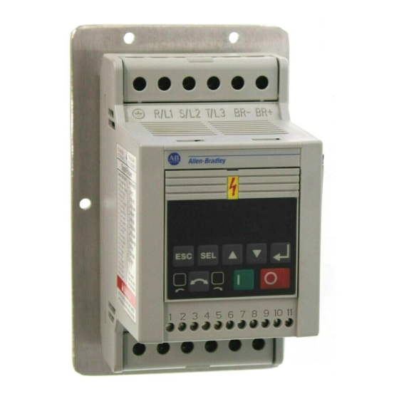
Power Wiring – TB1, TB2
TB1
Line Power & Dynamic
Brake Module Wiring
R/L1
S/L2
T/L3
BR–
BR+
ESC
SEL
1
2
3 4 5 6 7 8 9 10 11
TB3
Control Wiring
U/T1
V/T2
W/T3
DC–
DC+
TB2
Motor & Capacitor
Module Wiring
Wire Size and Torque Ranges
Min./Max. Wire Size
2
Model
Terminal
mm
(AWG)
4.0 kW (5 HP)
TB1, TB2
5.26-3.31 (10-12)
Three Phase
TB3
2.50-0.50 (14-22)
1.5 kW (2 HP)
TB1, TB2
5.26-3.31 (10-12)
Single Phase
TB3
2.50-0.50 (14-22)
3.31-0.82 (12-18)
All Other Ratings
TB1, TB2
2.50-0.50 (14-22)
TB3
Required Branch
Circuit Disconnect
Dynamic Brake
Module (optional)
Input Line
Protective Device
R/L1
S/L2
T/L3
BR–
PE
U/T1
V/T2
W/T3
DC–
Capacitor Module
Motor
(optional)
For single phase input applications, connect the AC input line to input terminals
S (L2) and T (L3).
Control Wiring – TB3
Analog Signal Follower Model
Preset Speed Model
Min./Max. Torque
Nm (lb.-in.)
1.35-0.90 (12-8)
0.80-0.40 (8-4)
1.35-0.90 (12-8)
0.80-0.40 (8-4)
1.35-0.90 (12-8)
0.80-0.40 (8-4)
TB1
BR+
DC+
TB2
10V DC Supply
Wiper
Common
4 – 20 mA Input
Reverse
Start
Common
Stop/Programmable
Normally Closed
Relay Common
Normally Open
SW1
SW2
Common
SW3
Run Reverse
Run Forward
Common
Stop/Programmable
Normally Closed
Relay Common
Normally Open
N.O. Momentary Contact
N.C. Momentary Contact
N.O. Maintained Contact
N.C. Maintained Contact
Wires must be shielded.
Troubleshooting
• Motor Does Not Start (No output voltage to motor)
1. Check power circuit.
- Check supply voltage.
- Check all fuses and disconnects.
2. Check the motor –
Verify that it is connected properly.
3. Check control input signals.
- Verify that START signal is present.
- Verify that the contact closure signal is present at TB3-8.
- Verify that either the RUN FORWARD or RUN REVERSE signal
is active, but NOT both.
4. Check P46 - [Input Mode].
- If P46 - [Input Mode] is set to 2, only the program keypad
module Start button will start the motor.
5. Cycle power or use P56 - [Reset Functions] if you changed
P46 - [Input Mode].
• Drive Started but Motor NOT Rotating
(P01 - [Output Frequency] displays "0.0")
1. Check the motor –
Verify that it is connected properly.
2. Check frequency source P06 - [Frequency Command].
- Verify that a frequency signal is present at terminal block
TB3. Either a –10 to +10V or 4-20 mA signal.
- Verify that Preset Frequencies are set properly.
3. Check control input signals.
- Verify that SW1, SW2 and SW3 are correct. (Refer to the
chart in the User Manual at the end of Chapter 5).
4. Check parameter settings.
- Verify that P59 - [Frequency Select] is showing the desired
frequency source.
- Verify that P58 - [Internal Frequency] is the desired value.
5. Cycle power or use P56 - [Reset Functions] if you changed
P46 - [Input Mode].
• Motor Not Accelerating Properly
1. Check the motor –
Verify that it is connected properly and that
no mechanical problems exist.
2. Check parameter settings.
- Verify that P30 - [Accel Time 1] or P69 - [Accel Time 2]
(whichever is current used) is set properly.
- Verify that P43 - [Current Limit] is set properly.
- Verify that P38 - [Boost Select] is set properly.
• Can Not Operate in "RUN FWD/RUN REV" Mode
1. Verify that P46 - [Input Mode] is set to 1.
2.
Verify that the contact closure signal is present at TB3-8
3. Verify that P73 - [Reverse Disable] and P74 - [Analog
Select] are not set to 1.
4. Verify that power has been cycled for above change to take
effect.
5. Verify that both RUN FORWARD and RUN REVERSE switches
are NOT closed simultaneously.
6. Cycle power or use P56 - [Reset Functions] if you changed
P46 - [Input Mode].
.
Advertisement

Related Manuals for Allen-Bradley 160 SSC


Summary of Contents for Allen-Bradley 160 SSC
- Page 1 Power Wiring – TB1, TB2 Control Wiring – TB3 Troubleshooting Analog Signal Follower Model • Motor Does Not Start (No output voltage to motor) Line Power & Dynamic 1. Check power circuit. Brake Module Wiring - Check supply voltage. R/L1 S/L2 T/L3 BR–...
- Page 2 1 second after the fault condition is IMPORTANT: This publication is designed as a reference removed. Refer to P51 - [Restart Time]. tool. The 160 SSC User Manual (publication 0160-5.15) must Overcurrent FauIt be consulted for more detailed information about parameters, Check short circuit at the drive output or excessive load conditions at the motor.
- Page 3 Keypad Module Description Programming Steps Action Description Parameter Number Display Parameter Value/Fault Number 1. To program the value of a Program These two digits display the active parameter number for These four digits display the parameter value or fault code Group parameter, enter the Program both Display and Program Group parameters.
- Page 4 Program Group Parameter List Display Group Parameter List Program Group Parameters Program Group Parameters (continued) Display Group Parameters No. Parameter Name Min/Max Range Units/Settings Default No. Parameter Name Min/Max Range Units/Settings Default No. Parameter Name Min/Max Range Units/Settings [Accel Time 1] 0.0-600 0.1 Sec 10.0...