Sign In
Upload
Download
Table of Contents
Contents
Add to my manuals
Delete from my manuals
Share
URL of this page:
HTML Link:
Bookmark this page
Add
Manual will be automatically added to "My Manuals"
Print this page
×
Bookmark added
×
Added to my manuals
Manuals
Brands
Allen-Bradley Manuals
Controller
1756-CN2/B
Installation instructions manual
Allen-Bradley 1756-CN2/B Installation Instructions Manual
Controlnet modules
Hide thumbs
1
2
Table Of Contents
3
4
5
6
7
8
9
10
11
12
13
14
15
16
17
18
19
20
21
22
23
24
25
26
27
28
29
30
31
32
33
34
35
36
37
38
39
40
41
42
43
44
45
46
47
48
49
50
51
52
page
of
52
Go
/
52
Contents
Table of Contents
Bookmarks
Table of Contents
Table of Contents
Additional Resources
Chapter 1 Controllogix-XT with Traditional Controllogix Components
Controllogix-XT Systems
Determine Module Slot Location
Installation Summary
Redundant Media
Set the Node Address
Install the Module
Connect the Module to a Controlnet Network
Remove the Module
Reset the Module to the Original Factory Settings
Keeper Configuration-Automatic Keeper Crossload
Connect a Programming Terminal to the Network with a 1786-CP Cable
Install the EDS File
Connect to the Module Via the USB Port
Redundant Media
Chapter 2 Installation Summary
Grounding Considerations
Set the Node Address
Install the Module
If You Use Screws to Mount the Module
Mount on a DIN Rail
Connect the Module to a Controlnet Network
Remove the Module
Chapter 3 Use Redundant Media
Additional Resources
Chapter 4
Set up a USB Driver
Appendix A
Interpret the OK Status Indicator
Interpret the Network Channel Status Indicators
Controlnet Communication Modules
OK Status Indicator and Display
Network Channel Status Indicators
Controlnet Communication Modules
OK Status Indicator and Display
Network Channel Status Indicators
1768-CNB and 1768-CNBR Controlnet Modules
Appendix B
OK Status Indicator and Display
Network Channel Status Indicators
Rockwell Automation Publication CNET-IN005A-EN-P - May
Advertisement
Quick Links
1
Table of Contents
2
Controllogix-Xt Systems
3
Interpret the Ok Status Indicator
4
Ok Status Indicator and Display
5
Ok Status Indicator and Display
Download this manual
Installation Instructions
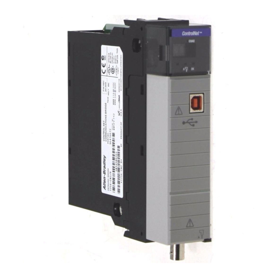
ControlNet Modules
Catalog Numbers 1756-CN2/B, 1756-CN2R/B, 1756-CN2RXT, 1756-CNB/E, 1756-CNBR/E, 1768-CNB,
1768-CNBR
Table of
Contents
Previous
Page
Next
Page
1
2
3
4
5
Advertisement
Table of Contents
Need help?
Do you have a question about the 1756-CN2/B and is the answer not in the manual?
Ask a question
Questions and answers
Related Manuals for Allen-Bradley 1756-CN2/B
Control Systems Allen-Bradley 1756-CNB User Manual
Controllogix redundancy system (186 pages)
Controller Allen-Bradley controllogix 1756-L55M12 User Manual
(142 pages)
Controller Allen-Bradley 1756-L61 User Manual
Controllogix system (238 pages)
Controller Allen-Bradley 1756-L61 ControlLogix 5561 Programming Manual
Logix5000 series (90 pages)
Controller Allen-Bradley Logix5000 Series Application Book
Compactflash file system (56 pages)
Controller Allen-Bradley 1756-CNBR/E Installation Instructions Manual
Controlnet modules (52 pages)
Controller Allen-Bradley 1756 ControlLogix Instruction Manual
Logix 5000 controllers (676 pages)
Controller Allen-Bradley LOGIX 5000 Reference Manual
Controllers advanced process control and drives and equipment phase and sequence instructions (561 pages)
Controller Allen-Bradley Logix 5000 Programming Manual
Controllers sequential function charts (92 pages)
Controller Allen-Bradley Logix 5000 Programming Manual
Controllers messages (38 pages)
Controller Allen-Bradley Logix 5000 Series Programming Manual
Controllers produced and consumed tags (48 pages)
Controller Allen-Bradley GuardLogix 1756 Product Information
(6 pages)
Controller Allen-Bradley 1756-L61S Reference Manual
Guardlogix controller systems (116 pages)
Controller Allen-Bradley 1756-HYD02 User Manual
Motion coordinate system (236 pages)
Controller Allen-Bradley ControlLogix System 1756-L55M Series User Manual
(435 pages)
Controller Allen-Bradley ControlLogix 1756-STRT3 Quick Start Manual
Starter kit (92 pages)
This manual is also suitable for:
1756-cn2rxt
1756-cnbr/e
1756-cnb/e
1768-cnb
1768-cnbr
1756-cn2r/b
Table of Contents
Print
Rename the bookmark
Delete bookmark?
Delete from my manuals?
Login
Sign In
OR
Sign in with Facebook
Sign in with Google
Upload manual
Upload from disk
Upload from URL


Need help?
Do you have a question about the 1756-CN2/B and is the answer not in the manual?
Questions and answers