
Related Manuals for Allen-Bradley 160 SSC


Summary of Contents for Allen-Bradley 160 SSC
- Page 1 Allen-Bradley Installation 160 SSC™ Variable Speed Manual Controller (Series B) 0.37 – 2.2 kW (1/2 – 3 HP) FRN 5.xx Table of Contents Index...
- Page 2 Reproduction of the content of this manual, in whole or in part, without written permission of the Rockwell Automation Company is prohibited. This manual is intended to guide qualified personnel in the installation and operation of this product. The information in this manual is organized in numbered chapters.
- Page 3 December, 1996. Please place this document in your manual for future reference. Important Note Bulletin 160 SSC Controllers with a catalog number suffix of “S01,” (i.e. 160S-AA02NS01) will have the “Motor Stall Fault” (F06, page 6-2) detection feature disabled. All other features specified in the User Manual will be operational.
- Page 4 Document Update 160 SSC™ Variable Speed Controller (Series B) This publication provides new and updated material for the 160 SSC Variable Speed Controller User Manual, publication 160-5.9, dated December, 1996. Please place this document in your manual for future reference.
- Page 5 160 SSC™ Variable Speed Controller (Series B) General Instructions for an Refer to Figure 1. EMC Compliant Installation Shielded Enclosure • Typical NEMA or IEC metal enclosures are adequate. • The ground connection of the shielded enclosure must be solidly connected to the PE terminal of the controller.
- Page 6 160 SSC™ Variable Speed Controller (Series B) Motor Cable • The cable between the controller and motor must be a 4-wire shielded cable (three phases and ground). Refer to Figures 2 & 3. • When using a line filter module as specified in Appendix A, motor...
- Page 7 160 SSC™ Variable Speed Controller (Series B) Control Cable • Control wiring must use shielded cable, or grounded metal conduit. Refer Figures 3 and 4. • The shield must be connected to signal common at both ends of the cable.
- Page 8 New features include: Configurable Terminal Block Input The parameter P46 – [Input Mode] has been Increased Low Speed Torque. expanded to provide greater flexibility. New The parameter P71 – [IR Compensation] was input modes include the ability to select added, allowing adjustment of the amount of secondary accel/decel times, switch between IR compensation desired.
- Page 9 This Page Intentionally Blank...
-
Page 10: Table Of Contents
General Information ........... 1–1 Conventions Used In This Manual . - Page 11 This Page Intentionally Blank...
- Page 12 It is your responsibility to Remove all packing material, thoroughly inspect the equipment before wedges, or braces from within and around the accepting the shipment from the freight company. controller. Remove all packing material from the Check the item(s) received against the purchase heat sink.
- Page 13 Î 0.75kW/1HP Rating: Î Î Î Î Î Î ALLEN-BRADLEY OPERATING AMBIENT TEMP: 0 – 50 C SHORT CIRCUIT CURRENT: 100KA POWER TERMINAL WIRE: Use 75 C Cu Wire – .75mm (12–18 AWG.) Torque 1.35 Nm (12 in.-lbs.) WARNING: ! Allow 1 Minute after power is removed before servicing.
-
Page 14: Controller Dimensions
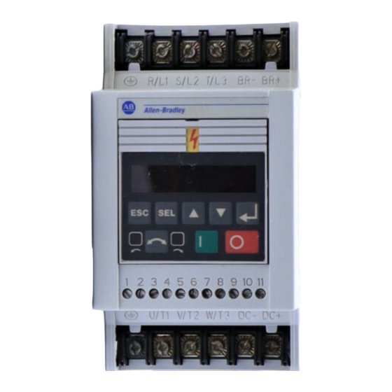
Take these actions to prolong controller life and performance: This product complies with Low Voltage Directive 72/23/EEC when conforming with the store within an ambient temperature range of following installation requirements: –40 to +85 C review the General Precautions section on store within a relative humidity range of 0% page 1–1, inside front cover, and other to 95%, non-condensing... - Page 15 Figure 2.1 below details the features of both the Analog Signal Follower and Preset Speed models. Important: The features are the same for single and three phase units. ATTENTION: The controller is intended to be commanded by control input signals that will start and stop the motor.
- Page 16 The controller is suitable for direct connection to AC power lines within the rated voltage of the controller (see Appendix A). Listed below are certain power line conditions which may cause component damage or reduction in product life. If any of the conditions exist as described in the table below, install “one”...
- Page 17 A variety of cable types are acceptable for Installations with long motor cables may require variable speed controller installations. For many the addition of output reactors to reduce voltage installations, unshielded cable is adequate, reflections at the motor, and reduce cable provided it can be separated from sensitive charging current.
- Page 18 380–460 V Ratings Ratings 2.2 kW (3 HP) (3 HP) 1.5 kW (2 HP) (2 HP) 0.75 kW (1 HP) (1 HP) 0.55 kW (0.75 HP) (0.75 HP) 0.37 kW (0.5 HP) (0.5 HP) 200–240 V Ratings Ratings 0.37 to 2.2 kW (0.5 to 3 HP) 2 thru 8 kHz 2–5...
- Page 19 run all signal wiring in either a shielded cable, or a separate metal conduit. You can control the output frequency of the controller via the Control Terminal Block (TB3) only connect shield wire at control terminal using a remote potentiometer, a –10 to +10 VDC block common terminals TB3-3 and TB3-7.
- Page 20 Ω Ω Ω 2–7...
- Page 21 Use P46 – [Input Mode] to select the control method for start, stop, and direction control. Important, settings 4 through 6 provide additional flexibility of TB3 control input terminal 8. Setting 0 — Three Wire Control. (This is the factory default setting). Refer to Figure 2.5 . Important: After a Stop input, the Start input Setting 1 —...
- Page 22 Accel 2 Accel 1 Decel 2 Decel 1 Controller Controller Disabled Enabled Local (TB3) Remote Control Control Important: In modes 4 through 6, Terminal TB3-8 is also used to clear faults. See Figure 2.12 for details. Important: The system programmer is responsible for returning terminal TB3-8 to its original state if necessary.
- Page 23 2–10...
-
Page 24: Features
The controller always powers up in the display The program keypad module is located on the front mode. While in this mode you may view all read panel of the controller. It features the following: only controller parameters, but not modify them. five keys on the module for display or programming controller parameters three keys for control inputs to the controller... - Page 25 ATTENTION: Ensure that you ATTENTION: This controller disconnect line power and wait contains ESD (Electrostatic one minute before installing or Discharge) sensitive parts and removing the program keypad assemblies. Static control precautions module. Failure to do so may are required when installing, testing, result in personal injury or death.
- Page 26 ATTENTION: ATTENTION: 4–1...
- Page 27 ATTENTION: 4–2...
-
Page 28: Programming Example
This chapter covers both display and program parameters. Display parameters are read only (they cannot be programmed), while program parameters can be changed to fit your motor control requirements. You must have a Program Keypad Module to view/change display and program parameters. -
Page 29: Display Group Parameters
This group of parameters consists of commonly viewed controller operating conditions such as controller output frequency, output voltage, output current and frequency command. All parameters in this group are read only. Important: The last user selected Display Group parameter will be saved on power down. Display Group Parameter Description 5–2... - Page 30 Display Group Parameter Description É É É É É É É É É É É É É É É É É É É É É É É É É É É 5–3...
- Page 31 This group contains parameters whose values can be programmed. Refer to the “Programming Example” outlined earlier in this chapter. Unless otherwise stated, parameters that are programmed while the controller is running take immediate effect. Program Group Parameter Description 5–4...
- Page 32 Program Group Parameter Description 5–5...
- Page 33 Program Group Parameter Description 5–6...
- Page 34 Program Group Parameter Description 5–7...
- Page 35 Program Group Parameter Description 5–8...
- Page 36 Program Group Parameter Description 5–9...
-
Page 37: Program Group Parameters
Program Group Parameter Description É É É É É É É É É É É É É É É 5–10... - Page 38 Program Group – Analog Signal Follower Model Only Parameter Description Preset Accel/Decel Chart For Preset Speed Model Only 5–11...
- Page 39 Program Group Parameter Description É É É É É É É É É É É É É É É É É É É É É É É É É É É É É É É É É É É É É...
- Page 40 Controllers without a program keypad module come equipped with a fault LED. When the fault LED illuminates, a fault condition exists. Important: If a fault occurs, it is important to address and correct the fault as well as the condition that caused the fault. To clear a fault, perform one of the following: Controllers equipped with a program keypad module will flash the display when a fault is...
- Page 41 6–2...
- Page 42 6–3...
- Page 43 6–4...
- Page 44 Tables A.1 and A.2 contain information that is unique to each SSC Controller rating. Table A.3 contains information that applies to all Controller ratings. A–1...
- Page 45 Î Î Î Î Î Î Î Î Î Î Î Î Î Î Î Î Î Î Î Î Î Î Î Î Î Î A–2...
- Page 46 A–3...
- Page 47 For All Controller Ratings – 0.37 to 2.2kW (1/2 to 3 HP) For Controller Ratings – 0.37 to 2.2kW (1/2 to 3 HP) A–4...
- Page 48 Use the drilling template at the back of the manual for mounting the controller. See Figure A.1 for details on controller dimensions and weights. There must be a minimum of 12.5mm (0.5 inches) clearance around all sides of the controller. Use either DIN rail or mounting holes.
- Page 49 Dimensions are shown in millimeters (inches). Dimensions are not to be used for manufacturing purposes. (.230) 86,4 (2.8) 4 places (3.4) (1.9) (.315) (.551) (.295) (1.1) A–6...
- Page 50 Dimensions are shown in millimeters (inches). Dimensions are not to be used for manufacturing purposes. 22,7 (.894) MODULE 40,2 45,4 (1.6) (1.8) 0,54 (.021) (2.8) (.199) Extension A–7...
- Page 51 Dimensions are shown in millimeters (inches). Dimensions are not to be used for manufacturing purposes. (2.36) (1.97) (.236) (7.87) – Approximate Lead Length (.197) (5.11) (5.98) (6.41) (6.85) Important: 3 Line Filter shown. 1 Line Filter is the same (2.95) size.
- Page 52 Dimensions are shown in millimeters (inches). Dimensions are not to be used for manufacturing purposes. (1.97) 110,9 (4.37) (.177) (1.5) Mounting Holes (5.51) 150,9 (5.94) (5.11) 254 (10) Approximate Lead Length A–9...
- Page 53 Dimensions are shown in millimeters (inches). Dimensions are not to be used for manufacturing purposes. 17,34 161,2 (0.68) Required (6.35) Overall Height for Removal with DeviceNet Module 167,82 (6.61) Overall Height with DeviceNet Connector A–10...
- Page 54 I–1...
- Page 55 I–2...
- Page 56 Attach template to mounting surface and drill four (4) 4.5 mm (0.177 inches) diameter holes. Dimensions are in millimeters [inches].
Need help?
Do you have a question about the 160 SSC and is the answer not in the manual?
Questions and answers